CMD flexacier 9000 User manual

exacier 9000
INSTALLATION AND MAINTENANCE INSTRUCTIONS
ACCOUPLEMENT ELASTIQUE//FLEXIBLE COUPLING//ELASTISCHE KUPPLUNG
®
winex 9000
®

ACCOUPLEMENT ELASTIQUE//FLEXIBLE COUPLING//ELASTISCHE KUPPLUNG
INSTALLATION AND MAINTENANCE INSTRUCTIONS
123
Enfiler le joint quadrilobe, puis le moyeu
Place rubber seal on shaft, then mount hub
Erst Gummidichtung aufschieben, dann Nabe
montieren.
Tolérances d’alignement - Alignment limits - Toleranzrichtwerte
Taille - Size - Größe 9000 ... 9002 9004 ... 9007 9009 ... 9016
r ; a mm 0,20 0,25 0,28
j mm 3 5 6
Pour toutes exécutions équilibrées dynamique-
ment, ou à jeu axial limité, prendre le tiers des
valeurs r et a.
Pendant l’opération d’alignement, tenir compte
des éventuelles déviations qui pourraient surve-
nir en cours de fonctionnement.
Chaque moyeu doit être arrêté axialement sur
son arbre. Chaque arbre doit avoir sa propre
butée.
When coupling is dynamically balanced or
equipped with limited end float kit, the align-
ment limits “a” and “r” must be divided by
three.
Take into account potential operating devia-
tions when making alignment.
Hubs shall be mounted with flange face flush
with shaft ends and be blocked axially.
Each shaft must have its own thrust bearing.
Bei sämtlichen dynamisch ausgewuchteten
Einrichtungen oder bei begrenztem Axialspiel sind
etwa 1/3 der “r” und “a” Werte einzuhalten.
Dabei sind die entsprechenden Betriebsbedingun-
gen zu berücksichtigen, die sich während des Be-
triebes einstellen können.
Jede Nabe muß axial auf der Welle gesichert sein.
Jede Welle muß ihren eigenen Anschlag haben,
wobei die Kupplung sich frei positionieren kann.
Contrôle de l’alignement en 4 points (r)
Check parallel alignment in 4 points (r)
Prüfung der Fluchtung an vier Stellen (r)
Contrôle de l’écartement en 4 points avec jeu de
cales (a)
Check gap and angular alignment with feeler
gage (a)
Zwischenabstand an vier Stellen auf Gleichheit
prüfen mit Fühlerlehre (a)
1
r
a
J
- 0,3
+ 0,3
- 0,5
+ 0,5
- 0,6
+ 0,6

456
Fixer les machines – Graisser rainures – Placer ressorts
Tighten foundation bolts – Pack grooves with grease
– Press springs into the grooves
Maschine befestigen – Zahnlücken mit Fett füllen
– Federsegmente einlegen.
Monter les 1/2 boitiers avec les joints papier et quadrilobe
Assemble 1/2 covers with paper gaskets and rubber
seals
Gehäusehälften mit Papierdichtung und Gummidichtung
einbauen
Serrer au couple (cf. tableau couple de serrage en page 4)
Bolt up in accordance with torque values (ref. tightening
torque chart page 4)
Verschrauben mit Anziehdrehmoment (siehe Anzie-
hdrehmoment auf Seite 4)
Lubrifiants – Lubricants – Schmiermittel
Graisse – Grease – Fette
NLGI n°2 T°=
CASTROL
Spheerol EPLX
200-2
ESSO
Beacon EP2
KLÜBER
Klüberlub BE
41 - 1501
MOBIL
Mobilux EP2
SHELL
Gadus S2V
220 2
TOTAL
Multis EP2
BARDAHL
GTU S-2
- Graisse avec intervalle de
renouvellement augmenté
jusqu’à 5 ans
- Grease with a longer renewal
interval of up to 5 years.
- Fett mit bis auf 5 Jahre ver-
längertem Wechselintervall
MOBILGREASE
XTC
- Pour une graisse équivalente chez un autre fournisseur, se renseigner auprès d’eux.
Les critères à vérifier sont notamment: Graisse NLGI grade 0 -1 avec additifs extrême
pression, savon Lihium Polymère, huile de base 680 cSt à 40°C, pénétration de 310 à
370 séparation d’huile sous centrifugation k36, 24h, 0% suivant ASTM D4425, Corrosion
«Passe» suivant ASTM D1743 et D4048.
- For equivalent grease from another supplier, please ask them for information.
The criteria to be checked include: NLGI grade 0 -1 grease with extreme pressure additives,
lithium soap/polymer, base oil 680 cSt at 40°, penetration value from 310 to 370, oil
separation under centrifugation K36, 24h, 0% according to ASTM D4425, compliant to
corrosion test according to ASTM D1743 and D4048.
Températures limites utilisation T° (relevées sur accouplement)
Operating limit temperatures T° (measured on coupling) T°=
Zulässige Betriebstemperaturen T° (gemessen an der Kupplung)
Masse de graisse par accouplement – Grease weight per coupling – Gewicht der Fettfüllung
Taille - Size - Größe 9000 9001 9002 9004 9007 9009 9011 9016
Kg 0,13 0,18 0,27 0,4 0,7 0,8 1 1,2
- 20°C
+ 110°C
2
- 20°C
+ 110°C
Remplir de graisse à la pompe via un des graisseurs
(1/8’’ GAZ), jusqu’à ce qu’elle déborde par le trou op-
posé.
ATTENTION : s’assurer que les bouchons sont bien re-
montes avant la mise en service.
Fill grease through (1/8’’ GAZ) plug with pump until an
excess appears at the opposite hole.
CAUTION : ensure that plugs have been inserted before
operating.
Fett mit einer Fettspritze durch eines der Sch-
mierstopfen (1/8“ GAS) einfüllen, bis es am Loch ge-
genüber herauskommt.
ACHTUNG : Prüfen, dass die Stopfen vor der Inbetriebna-
hme wieder richtig verschlossen sind.
7

MONTAGE
Alle Kupplungsteile reinigen.
VERBINDUNG VON NABEN UND WELLEN
a) Paßfederverbindung:
Paßfeder anpassen. Je nach Passungsart erleichtert
ein gleichmäßiges Erhitzen des Nabenkörpers auf
100°C bis 120°C die Montage. Die Paßfedernut ist
abzudichten.
b) Bei Schrumpfverbindung auf glatten Wellen, mit
einem Schrumpfmaß von 1,2 bis 1,6 0/00 erfolgt die
Erhitzung der Naben vorzugsweise im Ofen. Sie sollte
250°C bei einer Umgebungstemperatur der Welle
von 20°C betragen.
Vor der Erhitzung sind die Verschlußstopfen für die hy-
draulische Demontage zu entfernen und die Kontakt-
flächen zu entfetten. Die Dichtung muß vor der Hitze
der Nabe geschützt werden.
Ausrichtung und Demontage durch Schläge ist zu ver-
meiden.
Die bei der Ausrichtung, beim Zusammenbau, bei
der Schmierung und Wartung angewendete Sorgfalt
gewährleistet eine lange Lebensdauer der Kupplung.
EINBAU DER FEDERSEGMENTE
Die Kupplungen der Größen 9007 bis 9016 haben 2
Lagen gleicher Federsegmente. Wir Empfehlen eine
versetzte Anordnung der Segmente.
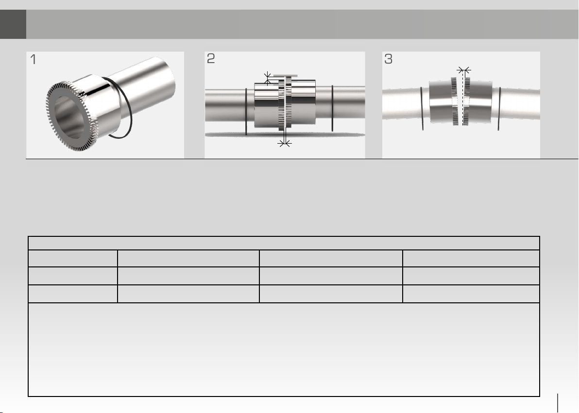
MOUNTING
Clean all parts of the coupling.
FITTING THE HUB ON SHAFT
a) Keyed fit assembly
Adjust key as necessary. Dependant upon type of ad-
justment and to facilitate fitting, we recommend uni-
form heating of the hub to about 100°C to 120°C.
Secure the seal.
b) Shrink fit assembly, with an interference of 1.2 to
1.6 0/00. Degrease all contact surfaces and remove
plugs from holes provided for hydraulic dismantling.
Heat preferably in a furnace – to 250°C assuming an
ambient temperature of 20°C.
Upon fitting, ensure protection of the seal from the
heat of the hub.
The use of a hammer (creating shocks) for fitting or
dismantling is not advised.
CARE TAKEN DURING ASSEMBLING AND ALIGNING,
TOGETHER WITH CORRECT LUBRICATION AND
MAINTENANCE, WILL ENSURE A SATISFACTORY
LIFE FOR THE COUPLINGS.
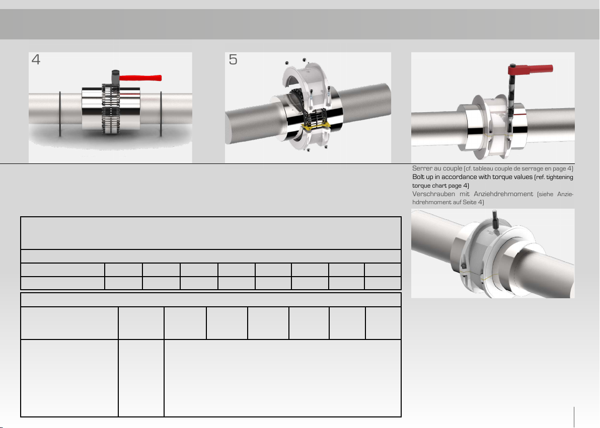
POSITIONING OF THE GRIDS
Couplings 9007 to 9016 include two identical spring
layers. We recommend a staggered arrangement of
the spring segments between layers.
MONTAGE
Nettoyer toutes les pièces de l’accouplement.
CALAGE DES MOYEUX SUR LES ARBRES
a) Assemblage claveté
Ajuster la clavette. Selon le type d’ajustement un
chauffage uniforme de l’ordre de 100°C à 120°C faci-
lite le montage. Etancher la rainure de clavette.
b) Assemblage par frettage sur arbre lisse, avec un
serrage de 1,2 à 1,6 0/00 , le chauffage sera fait de
préférence au four et devra atteindre 250°C pour
une température ambiante de l’ordre de 20°C. Avant
chauffage, enlever les bouchons prévus pour le dé-
montage hydraulique, et dégraisser les surfaces en
contact.
Le joint devra être protégé de la chaleur du moyeu.
Calage et démontage par chocs sont à proscrire.
LES SOINS APPORTÉS AU LIGNAGE, A L’ASSEM-
BLAGE, A LA LUBRIFICATION ET A L’ENTRETIEN, AS-
SURERONT LONGEVITE A L’ACCOUPLEMENT.
MONTAGE DES RESSORTS
Les accouplements tailles 9007 à 9016 comportent
deux couches de ressort identiques. Nous conseillons
de monter en quinconce les extrémités des segments
de chaque couche.
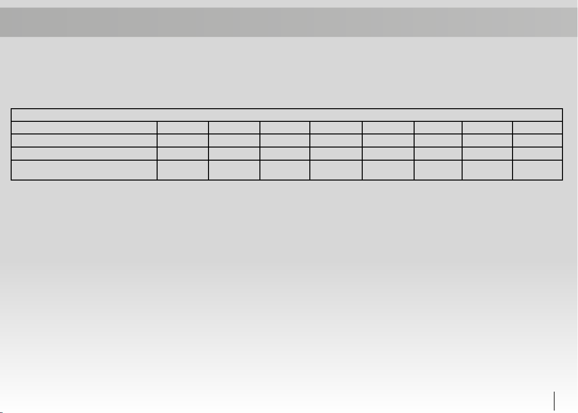
Nombre de segments total n - Total number of segments n - Zahl d. Segmente n
Taille – Size – Größe 9000 9001 9002 9004 9007 9009 9011 9016
n2 2 2 2 4 4 4 4
Nbre de couches - Nbr of layers - Zahl Schichten 1 1 1 1 2 2 2 2
3

ASSEMBLAGE
Aucun repère n’est à respecter pour le vis-à-vis des den-
tures sauf dans le cas où l’accouplement subit un équi-
librage dynamique.
Pour faciliter le glissement des boîtiers munis de leurs
joints, graisser le corps des moyeux
ASSEMBLING
No angular position of the hubs is required to the ex-
ception of dynamically balanced couplings where match
marks have to be aligned. Grease hub to facilitate sliding
of the half covers with their seal rings.
ZUSAMMENBAU
Nur bei dynamisch ausgewuchteten Kupplungen muß ein
Ausrichten der Kupplungsnaben zueinander nach den ange-
brachten Markierungen erfolgen.
Um das Aufschieben der Gehäusehälften zu erleichtern, wer-
den die Dichtflächen der Kupplungsnaben eingefettet.
ENTRETIEN
La fréquence de lubrification dépend directement du
type de lubrifiant choisi et des conditions de fonction-
nement. Les accouplements Flexacier peuvent être lu-
brifiés avec la plupart des graisses EP2 industrielles;
dans ce cas, ils devraient être relubrifiés annuelle-
ment.
Pour étendre l’intervalle entre 2 lubrifications à 5 ans
ou 40 000 heures, il est possible d’utiliser une graisse
adaptée (voir tableau de recommandations en page
2)
DEMONTAGE
Séparer les demi-boîtiers.
Démonter segment par segment en commençant par
une lame d’extrémité et de proche en proche, sur les
suivantes.
MAINTENANCE
The frequency of lubrication depends both on the type
of lubricant chosen and on operating conditions. Flexa-
cier couplings can be lubricated with most industrial
EP2 greases; in this case they should be re-lubricated
annually.
To extend the interval between 2 lubrications up to 5
years or 40.000 hours, it is possible to use a suitable
grease (see table of recommendations, page 2).
DISMANTLING
Separate the two half covers.
Remove the spring one segment at a time, beginning
with one end of the segment.
WARTUNG
Die Intervalle der Nachschmierung hängen direkt mit
dem gewählten Schmiermittel und den Einsatzbedin-
gungen zusammen. Die Flexacier Kupplungen können
mit den meisten EP2 Industrie- Fetten geschmiert
werden; in diesem Fall sollten sie jährlich nachgesch-
miert werden.
Will man den Intervall zwischen 2 Nachschmierungen
auf 5 Jahre oder 40.000 Stunden erweitern, kann
man dafür ein entsprechend geeignetes Fett verwen-
den (siehe Tabelle mit Empfehlungen auf Seite 2)
DEMONTAGE
Die Gehäusehälften trennen. Segment für Segment aus-
bauen, wobei man am Ende eines Segments beginnt.
Boulons d’assemblage des demi-boîtiers - Half cover fastener - Schrauben für Gehäusemontage
Taille-Size-Größe 9000 9001 9002 9004 9007 9009 9011 9016
Ø M * 8 8 8 10 10 12 12 12
Longueur-Length-Länge 30 30 30 45 45 55 55 55
Couple de serrage Nm
Tightening Torque - Anziehdrehmoment 12 12 12 23 23 43 43 43
* Vis CHC/Freinage par écrou Nylstop * Screws SKT cap/Locking by locknut * Innensechskantschraube/selbstsichernd
4

January 2020
CMD
BUREAU COMMERCIAL
36, Avenue de l’Europe
Immeuble l’Etendard - BP 43
78142 VELIZY-VILLACOUBLAY, FRANCE
+33 (0)1 34 63 12 24
CMD
SIÈGE SOCIAL
539, Avenue du Cateau
59400 CAMBRAI, FRANCE
+33 (0)3 27 73 53 11
www.cmd-couplings.com
www.cmdgears.com
ATTENTION
Consultez les exigences légales, réglementaires ou
spécifiques applicables aux equipements appropriés
de protection des éléments tournants . Respecter
toutes les règles de sécurité lors de l’installation ou
de l’entretien des accouplements.
Veiller à consigner électriquement la machine mo-
trice et à supprimer toute charge sur la machine à en-
trainer avant d’installer ou d’effectuer la maintenance
des accouplements.
NOTRE SERVICE APRES-VENTE se tient à votre dispo-
sition pour tous conseils sur exploitation et assistan-
ce.
ACHTUNG
Die gültigen Sicherheitsbestimmungen des jewei-
ligen Einsatzlandes sind zu beachten. Umlaufende
Teile müssen gemäß dem Produktsicherheitsgesetz
geschützt sein.
Bei Einbau oder Wartung der Kupplungen alle
Sicherheitsvorschriften beachten.
UNSER KUNDENDIENST steht Ihnen für alle
Ratschläge und Hilfeleistungen zur Verfügung.
CAUTION
Consult applicable local and national safety codes for
proper guarding of rotating members. Observe all
safety rules when installing or servicing couplings.
Lockout starting switch of prime mover and remove
all external loads drive before installing or servicing
couplings.
AFTER SALES SERVICE is available for any advice or
service you may require.
5
FCMD GmbH
Schmiedestrasse 5
45527 HATTINGEN, GERMANY
+49 (0) 2324 686 520
www.fcmd-gmbh.de
This manual suits for next models
1
Table of contents
Other CMD Industrial Equipment manuals
Popular Industrial Equipment manuals by other brands

Balluff
Balluff BOS R090K-U-RX10-S49 Series user guide

Siemens
Siemens milltronics ILE-37 APPLICATION EXAMPLES

Slee
Slee Cromatec I operating manual

CenturionPro
CenturionPro HP1 owner's manual

GÜDE
GÜDE GRS 375 Translation of the original instructions

Huawei
Huawei FusionModule 1000A40 Quick installation guide

Renishaw
Renishaw Kiosk workstation user guide

Aventics
Aventics RTC-BV operating instructions

Siemens
Siemens 3KL84 Series operating instructions

KMC Controls
KMC Controls KMCConquest HLO-1050 installation guide

Neslab
Neslab Steelhead 1 Instruction and operation manual

LNS
LNS HYDROBAR SPRINT S3 instruction manual