manuals.online logo
Brands
  1. Home
  2. •
  3. Brands
  4. •
  5. Omron
  6. •
  7. Industrial Equipment
  8. •
  9. Omron F3SG-RA User manual

Omron F3SG-RA User manual

Chipsmall Limited consists of a professional team with an average of over 10 year of expertise in the distribution
of electronic components. Based in Hongkong, we have already established firm and mutual-benefit business
relationships with customers from,Europe,America and south Asia,supplying obsolete and hard-to-find components
to meet their specific needs.
With the principle of “Quality Parts,Customers Priority,Honest Operation,and Considerate Service”,our business
mainly focus on the distribution of electronic components. Line cards we deal with include
Microchip,ALPS,ROHM,Xilinx,Pulse,ON,Everlight and Freescale. Main products comprise
IC,Modules,Potentiometer,IC Socket,Relay,Connector.Our parts cover such applications as commercial,industrial,
and automotives areas.
We are looking forward to setting up business relationship with you and hope to provide you with the best service
and solution. Let us make a better world for our industry!
Contact us
Tel: +86-755-8981 8866 Fax: +86-755-8427 6832
Email & Skype: [email protected]om Web: www.chipsmall.com
Address: A1208, Overseas Decoration Building, #122 Zhenhua RD., Futian, Shenzhen, China
  
1
Safety Light Curtain
F3SG-RA
Advanced Safety Light Curtain in
Rugged, IP67 Rated Housing
Rugged, IP67 rated housing resists washdown
Space-saving slim profile of 35x35 mm (1.37 in.)
Scan 45 code with smart phone for local language
support and troubleshooting guide
Built-in muting; requires no external muting controller
All models designed for global use. PNP/NPN output
selection by DIP switch
Resolution: 14 mm (finger protection) and 30 mm
(hand and arm protection) models
Cascaded designs possible: 3 segments, up to 255 beams
“Smart click” 1/8 turn quick connect M12 cables: for fast
installation and proper torque to ensure IP67 connection
14mm resolution up to 10.0 m (32 ft.) range in 160 to
2080 mm (6.3 to 81.9 inch) protective heights
30mm resolution up to 20.0 m (65 ft.) range in 190 to
2510 mm (7.3 to 98.7 inch) protective heights
Online
To access
light curta
your table
sticker tha
Also acce
check the
download
The intera
indicator c
DIP switc
cause of a
Language
Chinese,
Italian.
eMultilan
stroubleshoo
ain errors in yo
et or smartpho
at can be app
essible by com
eerror details
manuals from
active diagnos
color, indicato
hsettings to t
an error.
es include Eng
Korean, Japa
nguage S
oting support f
our local lang
one to scan a
plied to the ma
mputer, opera
in 8 language
ma dedicated
stics ask abou
or flashing fre
thoroughly an
glish, Spanish
anese, Germa
Support
for safety
guage use
aQR code
achine.
ators can
es and
dwebsite.
ut error
quency and
nalyze the
h, French,
an, and
Bu
Built
haza
cont
spec
warn
they
conn
Re
“Sma
allow
ensu
ilt-in Mu
t-in muting to
ard zone requ
roller. The bla
cific beams of
ning zone can
enter a dang
nected units w
duced W
art click” 1/8 t
wfast installat
ure IP67 conn
uting and
pass through
uires no exter
anking functio
fthe safety lig
nbe set to ale
ger zone using
when horizont
Wiring Wo
turn quick-con
tion and prop
nection.
dBlankin
hmaterials int
nal muting
on disables
ght curtain. A
ert people bef
gsingle or se
tally mounted
ork
nnect M12 ca
per torque to
ng
to the
fore
eries-
d.
ables
F3SG-RA
2
Ordering Information
Main Units
Safety Light Curtain
Finger protection Hand and arm protection
Model Number of beams Protective height
(mm)
F3SG-4RA0160-14 15 160
F3SG-4RA0240-14 23 240
F3SG-4RA0320-14 31 320
F3SG-4RA0400-14 39 400
F3SG-4RA0480-14 47 480
F3SG-4RA0560-14 55 560
F3SG-4RA0640-14 63 640
F3SG-4RA0720-14 71 720
F3SG-4RA0800-14 79 800
F3SG-4RA0880-14 87 880
F3SG-4RA0960-14 95 960
F3SG-4RA1040-14 103 1,040
F3SG-4RA1120-14 111 1,120
F3SG-4RA1200-14 119 1,200
F3SG-4RA1280-14 127 1,280
F3SG-4RA1360-14 135 1,360
F3SG-4RA1440-14 143 1,440
F3SG-4RA1520-14 151 1,520
F3SG-4RA1600-14 159 1,600
F3SG-4RA1680-14 167 1,680
F3SG-4RA1760-14 175 1,760
F3SG-4RA1840-14 183 1,840
F3SG-4RA1920-14 191 1,920
F3SG-4RA2000-14 199 2,000
F3SG-4RA2080-14 207 2,080
Model Number of beams Protective height
(mm)
F3SG-4RA0190-30 8 190
F3SG-4RA0270-30 12 270
F3SG-4RA0350-30 16 350
F3SG-4RA0430-30 20 430
F3SG-4RA0510-30 24 510
F3SG-4RA0590-30 28 590
F3SG-4RA0670-30 32 670
F3SG-4RA0750-30 36 750
F3SG-4RA0830-30 40 830
F3SG-4RA0910-30 44 910
F3SG-4RA0990-30 48 990
F3SG-4RA1070-30 52 1,070
F3SG-4RA1150-30 56 1,150
F3SG-4RA1230-30 60 1,230
F3SG-4RA1310-30 64 1,310
F3SG-4RA1390-30 68 1,390
F3SG-4RA1470-30 72 1,470
F3SG-4RA1550-30 76 1,550
F3SG-4RA1630-30 80 1,630
F3SG-4RA1710-30 84 1,710
F3SG-4RA1790-30 88 1,790
F3SG-4RA1870-30 92 1,870
F3SG-4RA1950-30 96 1,950
F3SG-4RA2030-30 100 2,030
F3SG-4RA2110-30 104 2,110
F3SG-4RA2190-30 108 2,190
F3SG-4RA2270-30 112 2,270
F3SG-4RA2350-30 116 2,350
F3SG-4RA2430-30 120 2,430
F3SG-4RA2510-30 124 2,510
F3SG-RA
3
Accessories (Sold separately)
Single-ended Connector Cable
Double-ended Cable
For cable extension and simple wiring
Y-Joint Plug/Socket Connector for Advance type F3SG-RA
Cascading Cable (Two cables per set, for emitter and receiver)
Appearance Type
Cable length
Specifications Model
For emitter
M12 connector
(5-pin), 5 wires
Color: Gray
3 m F39-JG3A-L
7 m F39-JG7A-L
10 m F39-JG10A-L
15 m F39-JG15A-L
20 m F39-JG20A-L
For receiver
M12 connector
(8-pin), 8 wires
Color: Black
3 m F39-JG3A-D
7 m F39-JG7A-D
10 m F39-JG10A-D
15 m F39-JG15A-D
20 m F39-JG20A-D
Appearance Type
Cable length
Specifications Model
For emitter
M12 connector
(5-pin)
on both ends
Color: Gray
0.5 m F39-JGR5B-L
1 m F39-JG1B-L
3 m F39-JG3B-L
5 m F39-JG5B-L
7 m F39-JG7B-L
10 m F39-JG10B-L
15 m F39-JG15B-L
20 m F39-JG20B-L
For receiver
M12 connector
(8-pin)
on both ends
Color: Black
0.5 m F39-JGR5B-D
1 m F39-JG1B-D
3 m F39-JG3B-D
5 m F39-JG5B-D
7 m F39-JG7B-D
10 m F39-JG10B-D
15 m F39-JG15B-D
20 m F39-JG20B-D
Appearance Type
Cable length
Specifications Model
M12 connectors.
Used for reduced
wiring.
0.5 m F39-GCNY2
Appearance Type
Cable length
Specifications Model
Emitter cable:
Cap (5-pin), M12
connector (5-pin)
Receiver cable:
Cap (8-pin), M12
connector (8-pin)
0.2 m F39-JGR2W
53214
Female 12345+24 VDC
TEST
0 VDC
Not used
Not used
Brown
Black
Blue
White
Yellow
58432176
Female 27561+24 VDC
0 VDC
OSSD 1
OSSD 2
RESET
Brown
Blue
Black
White
Yellow
8AUX Red
3MUTEAGray
4MUTEBPink
Brown
Blue
Black
White
Yellow
1324553214Brown
Blue
Black
White
Yellow
13245Female 54123Male
Connected to Power Cable
or Double-Ended Cable
Connected to Single-Ended Cable, or
Double-Ended cable
Brown
Blue
Black
White
Yellow
Red
Gray
Pink
Blue
Black
White
Yellow
Red
Gray
Pink
27561834Brown
584321765867123427561834
Connected to Power Cable
or Double-Ended Cable
Connected to Single-Ended Cable, or
Double-Ended cable
Female Male
F3SG-RAEmitterDouble-ended Cable
F39-JG@B-L(Gray)
Single-ended Connector
Cable
F39-JG@A-D(Black)
Y-Joint Plug/
Socket Connector for Advance
F39-GCNY2
F3SG-RAReceiver
Secondary
sensor 1
(Emitter)
Secondary
sensor 1
(Receiver)
Primary
sensor
(Emitter)
Primary
sensor
(Receiver)
Cascading Cable
F39-JGR2W
Cable
F39-JG@@@-L
Cable
F39-JG@@@-D
F3SG-RA
4
Sensor Mounting Brackets
*1 Two brackets per set
[for F3SG-@RA@@@@-14]
- Protective height of 0160 to 1200: 2 sets, Protective height of 1280 to 2080: 3 sets
[for F3SG-@RA@@@@-30]
- Protective height of 0190 to 1230: 2 sets, Protective height of 1310 to 2270: 3 sets, Protective height of 2350 to 2510: 4 sets
*2 Top/Bottom Adjustable Bracket cannot be used with the Standard Fixed Bracket. Use with the Standard Adjustable Bracket.
(See *1 for the number of required brackets.)
Interface units and configuration tool SD Manager 2
Lamp
End Cap
Appearance Specification Application Model
Standard Fixed
Bracket
Bracket to mount the F3SG-R.
Side mounting and backside mounting possible.
(Included in the F3SG-R product package. See *1 below
for the number of included brackets.)
F39-LGF
Standard
Adjustable
Bracket
Bracket to mount the F3SG-R.
Beam alignment after mounting
possible.The angle adjustment range is ±15°.
Side mounting and backside mounting possible.
(Sold separately. See
*1
below for the number of required brackets.)
F39-LGA
Top/Bottom
Adjustable Bracket *2
Bracket to mount the F3SG-R. Use this bracket at the
top and bottom positions of the F3SG-R.
Beam alignment after mounting possible.
The angle adjustment range is ±22.5°.
Side mounting and backside mounting possible.
(Sold separately. 4 brackets per set.)
F39-LGTB
Top/Bottom
Adjustable Bracket *2
(For user-made
mounting part)
Top/Bottom Adjustable Bracket without a bracket to
mount to the wall. Use the user's own wall mounting part
to suit the machine.
(Sold separately. 4 brackets per set.)
F39-LGTB-1
Appearance Type Specifications Model
SD Manager2
The Configuration Tool SD Manager 2 is available to
download from our website at
http://www.omron247.com/ safety_light_curtain/
f3sg_ra/Software tools/SD Manager 2 Configurator.
To change the settings of the F3SG-RA using SD
Manager 2, it is necessary to set the receiver's two
DIP switches No. 8 to ON.
−
Interface Unit F39-GIF interface unit to connect the F3SG-RA
receiver to a USB port of the PC F39-GIF
Bluetooth unit F39-BT bluetooth unit to enable bluetooth on the
F3SG-RA F39-BT
Appearance Type Specifications Model
Lamp unit The lamp unit can be connected to a receiver and
turned ON based on the operation of F3SG-RA.
The lamp can indicate red, orange, and green colors,
to which three different states can be assigned.
F39-LP
Bluetooth + Lamp unit F39-BTLP
Appearance Specifications Model
Housing color: Black
For both emitter and receiver
(Attached to the F3SG-R. The End Cap can be purchased if lost.)
F39-CNM
F3SG-RA
5
Spatter Protection Cover(Two covers per set, for emitter and receiver)
Spatter Protection Covers include mounting brackets.
For Safety Light Curtain models of the protective height of 2,000 mm or longer, use two Spatter Protection Covers of different lengths.
Note: The operating range of the Safety Light Curtain attached with the product is 10% shorter than the rating.
Test Rod
Appearance Safety Light Curtain Model Model
Finger protection Hand and arm protection
F3SG-@RA0160-14 F3SG-@RA0190-30 F39-HGA0200
F3SG-@RA0240-14 F3SG-@RA0270-30 F39-HGA0280
F3SG-@RA0320-14 F3SG-@RA0350-30 F39-HGA0360
F3SG-@RA0400-14 F3SG-@RA0430-30 F39-HGA0440
F3SG-@RA0480-14 F3SG-@RA0510-30 F39-HGA0520
F3SG-@RA0560-14 F3SG-@RA0590-30 F39-HGA0600
F3SG-@RA0640-14 F3SG-@RA0670-30 F39-HGA0680
F3SG-@RA0720-14 F3SG-@RA0750-30 F39-HGA0760
F3SG-@RA0800-14 F3SG-@RA0830-30 F39-HGA0840
F3SG-@RA0880-14 F3SG-@RA0910-30 F39-HGA0920
F3SG-@RA0960-14 F3SG-@RA0990-30 F39-HGA1000
F3SG-@RA1040-14 F3SG-@RA1070-30 F39-HGA1080
F3SG-@RA1120-14 F3SG-@RA1150-30 F39-HGA1160
F3SG-@RA1200-14 F3SG-@RA1230-30 F39-HGA1240
F3SG-@RA1280-14 F3SG-@RA1310-30 F39-HGA1320
F3SG-@RA1360-14 F3SG-@RA1390-30 F39-HGA1400
F3SG-@RA1440-14 F3SG-@RA1470-30 F39-HGA1480
F3SG-@RA1520-14 F3SG-@RA1550-30 F39-HGA1560
F3SG-@RA1600-14 F3SG-@RA1630-30 F39-HGA1640
F3SG-@RA1680-14 F3SG-@RA1710-30 F39-HGA1720
F3SG-@RA1760-14 F3SG-@RA1790-30 F39-HGA1800
F3SG-@RA1840-14 F3SG-@RA1870-30 F39-HGA1880
F3SG-@RA1920-14 F3SG-@RA1950-30 F39-HGA1960
F3SG-@RA2000-14 F3SG-@RA2030-30
F39-HGA1480
F39-HGA0550
F3SG-@RA2080-14 F3SG-@RA2110-30
F39-HGA1560
F39-HGA0550
−F3SG-@RA2190-30
F39-HGA1640
F39-HGA0550
−F3SG-@RA2270-30
F39-HGA1720
F39-HGA0550
−F3SG-@RA2350-30
F39-HGA1800
F39-HGA0550
−F3SG-@RA2430-30
F39-HGA1880
F39-HGA0550
−F3SG-@RA2510-30
F39-HGA1960
F39-HGA0550
Diameter Model
14 mm dia. STI-TO14
30 mm dia. STI-TO30
F3SG-RA
6
Ratings and Specifications
Main unit
F3SG-4RA-14 F3SG-4RA-30
Type of ESPE (IEC 61496-1) Type 4 F3SG-4RA-14/-30
Performance
Object Resolution
(Detection Capability)
Opaque objects
14-mm dia. 30-mm dia.
Beam Gap 10 mm 20 mm
Number of Beams 15 to 207 8 to 124
Lens Size 5.2 × 3.4 (W× H) mm 7-mm dia.
Protective Height 160 to 2080 mm (6.3 to 81.9 inch) 190 to 2510 mm (7.3 to 98.7 inch)
Operating Range Long 0.3 to 10.0 m (1 to 32 ft.) 0.3 to 20.0 m (1 to 65 ft.)
Short 0.3 to 3.0 m (1 to 10 ft.) 0.3 to 7.0 m (1 to 23 ft.)
Response Time
ON to OFF Normal mode: 8 to 18 ms max. *1
Slow mode: 16 to 36 ms max. *1 *2
OFF to ON 40 to 90 ms max. *1
*1 Response time when used in one segment system or in cascaded connection.
Refer to page 8.
*2 Selectable by Configuration Tool.
Effective Aperture Angle
(EAA) (IEC 61496-2)
Type 4 ±2.5° max., emitter and receiver at operating range of 3 m or greater
Light Source Infrared LEDs, Wavelength: 870 nm
Startup Waiting Time 2 s max.
Electrical
Power Supply Voltage (Vs) SELV/PELV24 VDC±20% (ripple p-p 10% max.)
Current Consumption Refer to page 8 .
Safety Outputs (OSSD)
Two PNP or NPN transistor outputs (PNP or NPN is selectable by DIP Switch.)
Load current of 300 mA max., Residual voltage of 2 Vmax. (except for voltage drop due to cable
extension), Capacitive load of 1 μF max., Inductive load of 2.2 H max. *1
Leakage current of 1 mA max. (PNP), 2 mA max. (NPN) *2
*1 The load inductance is the maximum value when the safety output frequently repeats ON and
OFF. When you use the safety output at 4 Hz or less, the usable load inductance becomes
larger.
*2 These values must be taken into consideration when connecting elements including a
capacitive load such as a capacitor.
Auxiliary Output One PNP or NPN transistor output (PNP or NPN is selectable by DIP Switch.)
Load current of 100 mA max., Residual voltage of 2 Vmax .
Output Operation
Mode
Safety Output Light-ON (Safety output is enabled when the receiver receives an emitting signal.)
Auxiliary Output Muting or Override output (default) (Configurable by Configuration Tool)
Input Voltage
ON Voltage
TEST:
24 VActive: 9 Vto Vs (sink current 3 mA max.) *
0 VActive: 0 to 3 V(source current 3 mA max.)
MUTE A/B:
PNP: Vs to Vs-3 V(sink current 3 mA max.) *
NPN: 0 to 3 V(source current 3 mA max.)
RESET:
PNP: Vs to Vs-3 V(sink current 5 mA max.) *
NPN: 0 to 3 V(source current 5 mA max.)
OFF Voltage
TEST:
24 VActive : 0 to 1.5 Vor open
0 VActive : 9 Vto Vs or open
MUTE A/B, RESET:
PNP: 0 to 1/2 Vs, or open *
NPN: 1/2 Vs to Vs, or open *
*TheVs indicates a supply voltage value in your environment.
Overvoltage Category (IEC 60664-1) II
Indicators Refer to page 10.
Protective Circuit Output short protection, Power supply reverse polarity protection
Insulation Resistance 20 MΩor higher (500 VDC megger)
Dielectric Strength 1,000 VAC, 50/60 Hz (1 min)
Functional
Mutual Interference Prevention (Scan Code) This function prevents mutual interference in up to two F3SG-RA systems.
Cascade Connection
Number of cascaded segments: 3 max.
Total number of beams: 255 max.
Cable lengths between sensors: 10 m max.
Test Function Self-test (at power-on, and during operation)
External test (light emission stop function by test input)
Safety-Related Functions
Interlock
External device monitoring (EDM)
Pre-reset
Fixed blanking/Floating blanking
Reduced resolution
Muting/Override
Scan code selection
PNP/NPN selection
Response time adjustment
F3SG-RA
7
Environ-
mental
Ambient Temperature Operating -10 to 55°C (14 to 131°F) (non-icing)
Storage -25 to 70°C (-13 to 158°F)
Ambient Humidity Operating 35% to 85% (non-condensing)
Storage 35% to 95%
Ambient Illuminance Incandescent lamp: 3,000 Ix max. on receiver surface
Sunlight: 10,000 Ix max. on receiver surface
Degree of Protection (IEC 60529) IP65 and IP67
Vibration Resistance (IEC 61496-1) 10 to 55 Hz, Multiple amplitude of 0.7 mm, 20 sweeps for all 3 axes
Shock Resistance (IEC 61496-1) 100 m/s2, 1000 shocks for all 3 axes
Pollution Degree (IEC 60664-1) Pollution Degree 3
Connec-
tions
Power cable
Type of Connection
M12 connectors: 5-pin emitter and 8-pin receiver, IP67 rated when mated, Cables prewired to the sensors
Number of Wires Emitter: 5, Receiver: 8
Cable Length 0.3 m
Cable Diameter 6 mm
Minimum Bending
Radius R5 mm
Cascading cable
Type of Connection M12 connectors: 5-pin emitter and 8-pin receiver, IP67 rated when mated
Number of Wires Emitter: 5, Receiver: 8
Cable Length 0.2 m
Cable Diameter 6 mm
Minimum Bending
Radius R5 mm
Extension cable
- Single-ended cable
- Double-ended cable
Type of Connection M12 connectors: 5-pin emitter and 8-pin receiver, IP67 rated when mated
Number of Wires Emitter: 5, Receiver: 8
Cable Length Refer to page 3.
Cable Diameter 6.6 mm
Minimum Bending
Radius R36 mm
Extension of Power Cable 100 m max.
Material
Material
Housing: Aluminum
Cap: PBT
Front window: PMMA
Cable: Oil resistant PVC
Mounting Bracket: ZDC2
FE plate: SUS
Weight (packaged) Refer to page 8.
Included Accessories
Safety Precautions, Quick Installation Manual, Standard Fixed Bracket*, Troubleshooting Guide
Sticker, Warning Zone Label
* The quantity of Standard Fixed Brackets included varies depending on the protective height.
[F3SG-RA-14]
- Protective height of 0160 to 1200: 2 sets
- Protective height of 1280 to 2080: 3 sets
[F3SG-RA-30]
- Protective height of 0190 to 1230: 2 sets
- Protective height of 1310 to 2270: 3 sets
- Protective height of 2350 to 2510: 4 sets
Conformity
Conforming standards Refer to page 19.
Type of ESPE (IEC 61496-1) Type 4
Performance Level
(PL)/Safety category
Type 4 PL e/Category 4 (EN ISO 13849-1:2008)
PFHd 1.1 × 10⁻⁸ (IEC 61508)
Proof test interval TMEvery 20 years (IEC 61508)
SFF 99% (IEC 61508)
HFT 1 (IEC 61508)
Classification Type B (IEC 61508-2)
F3SG-4RA-14 F3SG-4RA-30
F3SG-RA
8
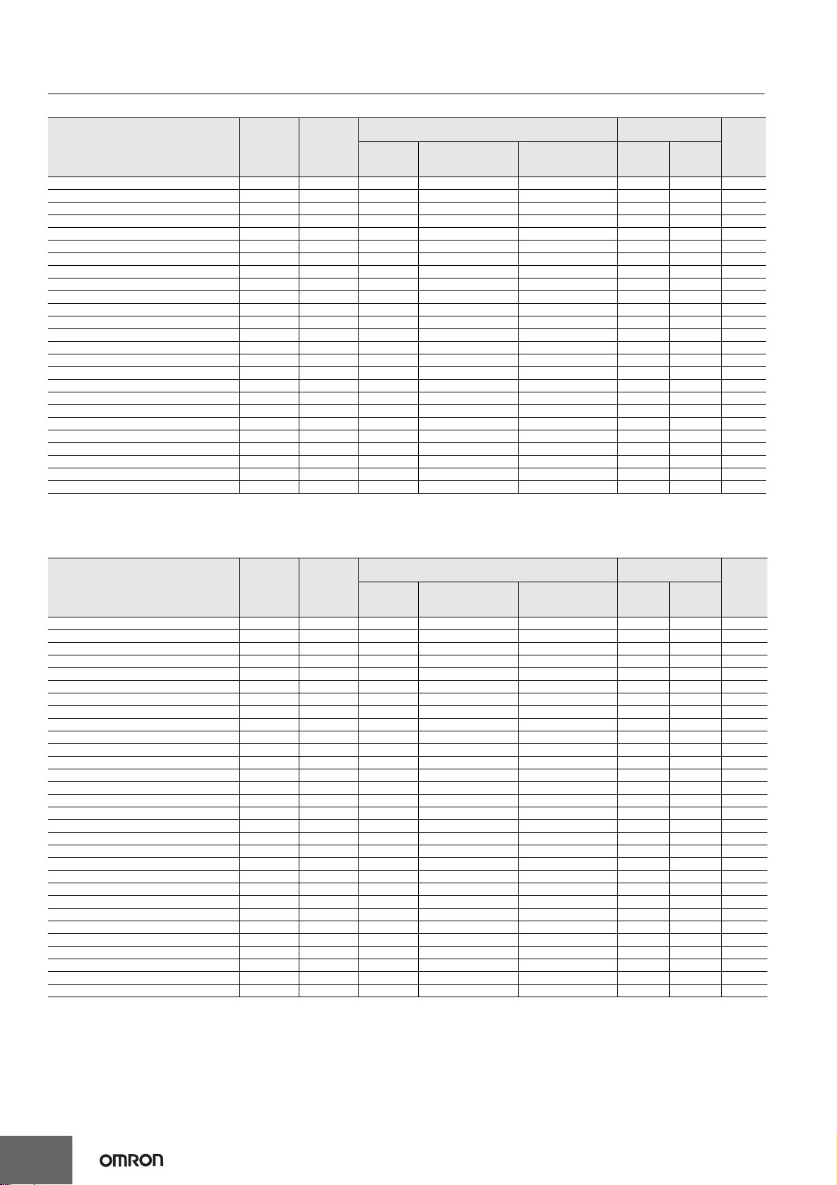
List of Models/Response Time/Current Consumption/Weight
F3SG-4RA-14
F3SG-4RA-30
Model Number of
Beams
Protective
Height
[mm]
Response Time [ms] Current
Consumption [mA] Weight
[kg]*2
ON →
OFF*1
OFF
(Synchronized)
→ ON
OFF
(Not synchronized)
→ ON
Emitter Receiver
F3SG-4RA0160-14 15 160 8 40 140 40 75 1.8
F3SG-4RA0240-14 23 240 8 40 140 45 75 2.0
F3SG-4RA0320-14 31 320 8 40 140 55 75 2.2
F3SG-4RA0400-14 39 400 8 40 140 60 80 2.7
F3SG-4RA0480-14 47 480 13 65 165 50 80 2.9
F3SG-4RA0560-14 55 560 13 65 165 55 80 3.1
F3SG-4RA0640-14 63 640 13 65 165 60 85 3.3
F3SG-4RA0720-14 71 720 13 65 165 65 85 3.9
F3SG-4RA0800-14 79 800 13 65 165 65 90 4.1
F3SG-4RA0880-14 87 880 13 65 165 70 90 4.3
F3SG-4RA0960-14 95 960 13 65 165 75 90 4.5
F3SG-4RA1040-14 103 1040 13 65 165 80 95 4.7
F3SG-4RA1120-14 111 1120 13 65 165 85 95 4.8
F3SG-4RA1200-14 119 1200 13 65 165 90 100 5.0
F3SG-4RA1280-14 127 1280 13 65 165 95 100 5.2
F3SG-4RA1360-14 135 1360 13 65 165 95 105 5.6
F3SG-4RA1440-14 143 1440 18 90 190 85 105 5.8
F3SG-4RA1520-14 151 1520 18 90 190 90 105 6.0
F3SG-4RA1600-14 159 1600 18 90 190 90 110 6.6
F3SG-4RA1680-14 167 1680 18 90 190 95 110 6.8
F3SG-4RA1760-14 175 1760 18 90 190 100 115 7.0
F3SG-4RA1840-14 183 1840 18 90 190 100 115 7.2
F3SG-4RA1920-14 191 1920 18 90 190 105 120 7.3
F3SG-4RA2000-14 199 2000 18 90 190 105 120 7.5
F3SG-4RA2080-14 207 2080 18 90 190 110 125 8.1
*1 The response times are values when Scan Code is set at Code B. The response times for Code A are 1 ms shorter than these values.
*2 The weight includes an emitter, a receiver and included brackets in a product package.
Model Number of
Beams
Protective
Height
[mm]
Response Time [ms] Current
Consumption [mA] Weight
[kg]*2
ON →
OFF*1
OFF
(Synchronized)
→ ON
OFF
(Not synchronized)
→ ON
Emitter Receiver
F3SG-4RA0190-30 8 190 8 40 140 35 75 1.8
F3SG-4RA0270-30 12 270 8 40 140 35 75 2.0
F3SG-4RA0350-30 16 350 8 40 140 40 75 2.2
F3SG-4RA0430-30 20 430 8 40 140 45 75 2.7
F3SG-4RA0510-30 24 510 8 40 140 50 75 2.9
F3SG-4RA0590-30 28 590 8 40 140 50 75 3.1
F3SG-4RA0670-30 32 670 8 40 140 55 75 3.3
F3SG-4RA0750-30 36 750 8 40 140 60 80 3.9
F3SG-4RA0830-30 40 830 8 40 140 65 80 4.0
F3SG-4RA0910-30 44 910 13 65 165 50 80 4.2
F3SG-4RA0990-30 48 990 13 65 165 50 80 4.4
F3SG-4RA1070-30 52 1070 13 65 165 55 80 4.6
F3SG-4RA1150-30 56 1150 13 65 165 55 85 4.8
F3SG-4RA1230-30 60 1230 13 65 165 55 85 4.9
F3SG-4RA1310-30 64 1310 13 65 165 60 85 5.1
F3SG-4RA1390-30 68 1390 13 65 165 60 85 5.6
F3SG-4RA1470-30 72 1470 13 65 165 65 85 5.8
F3SG-4RA1550-30 76 1550 13 65 165 65 90 6.0
F3SG-4RA1630-30 80 1630 13 65 165 70 90 6.5
F3SG-4RA1710-30 84 1710 13 65 165 70 90 6.7
F3SG-4RA1790-30 88 1790 13 65 165 70 90 6.9
F3SG-4RA1870-30 92 1870 13 65 165 75 90 7.1
F3SG-4RA1950-30 96 1950 13 65 165 75 95 7.3
F3SG-4RA2030-30 100 2030 13 65 165 80 95 7.4
F3SG-4RA2110-30 104 2110 13 65 165 80 95 8.0
F3SG-4RA2190-30 108 2190 13 65 165 85 95 8.2
F3SG-4RA2270-30 112 2270 13 65 165 85 100 8.4
F3SG-4RA2350-30 116 2350 13 65 165 85 100 8.8
F3SG-4RA2430-30 120 2430 13 65 165 90 100 8.9
F3SG-4RA2510-30 124 2510 13 65 165 90 100 9.1
*1 The response times are values when Scan Code is set at Code B. The response times for Code A are 1 ms shorter than these values.
The maximum speed of movement of a test rod up to which the detection capability is maintained is 2.0 m/s.
*2 The weight includes an emitter, a receiver and included brackets in a product package.
F3SG-RA
9
Legislation and Standards
1. The F3SG-R does not receive type approval provided by Article 44-2 of the Industrial Safety and Health Act of Japan. When using the F3SG-R
in Japan as a "safety system for pressing or shearing machines" prescribed in Article 42 of that law, the machine control system must receive
type approval.
2. The F3SG-R is electro-sensitive protective equipment (ESPE) in accordance with European Union (EU) Machinery Directive Index Annex V,
Item 2.
3. EC Declaration of Conformity
OMRON declares that the F3SG-R is in conformity with the requirements of the following EC Directives:
Machinery Directive 2006/42/EC
EMC Directive 2004/108/EC
4. Conforming Standards
(1) European standards
EN61496-1 (Type 4 ESPE), EN 61496-2 (Type 4 AOPD), EN61508-1 through -4 (SIL 3 for Type 4), EN ISO 13849-1:2008 (PL e, Category
4 for Type 4 and PL c)
(2) International standards
IEC61496-1 (Type 4 ESPE), IEC61496-2 (Type 4 AOPD), IEC61508-1 through -4 (SIL 3 for Type 4), ISO 13849-1:2006 (PL e, Category 4
for Type 4
5.
(1) JIS standards
JIS B 9704-1 (Type 4 ESPE), JIS B 9704-2 (Type 4 AOPD)
(2) North American standards
UL61496-1(Type 4 ESPE), UL61496-2(Type 4 AOPD), UL508, UL1998,
CAN/CSA C22.2 No.14, CAN/CSA C22.2 No.0.8
(3) Chinese standards
GB4584(Specification of active opto-electronic protective devices for presses)
6. Third-Party Certifications
(1) TÜVSÜD
•EC Type-Examination certificate:
EU Machinery Directive, Type 4 ESPE (EN61496-1), Type 4 AOPD (EN 61496-2)
•Certificate:
Type 4 ESPE (EN61496-1), Type 4 AOPD (EN61496-2), EN 61508-1 through -4 (SIL 3 for Type 4), EN ISO 13849-1:2008 (PL e,
Category 4 for Type 4,)
(2) UL
•UL Listing:
Type 4 ESPE (UL61496-1), Type 4 AOPD (UL61496-2), UL508, UL1998, CAN/CSA C22.2 No.14, CAN/CSA C22.2 No.0.8
(3) China National Casting and Forging Machines Quality Supervision and Inspection Center
•Certificate:
GB4584 (Specification of active opto-electronic protective devices for presses)
7. Other Standards
The F3SG-R is designed according to the standards listed below. To make sure that the final system complies with the following standards and
regulations, you are asked to design and use it in accordance with all other related standards, laws, and regulations. If you have any questions,
consult with specialized organizations such as the body responsible for prescribing and/or enforcing machinery safety regulations in the location
where the equipment is to be used.
•European Standards: EN415-4, EN691-1, EN692, EN693, IEC/TS 62046
•U.S. Occupational Safety and Health Standards: OSHA 29 CFR 1910.212
•U.S. Occupational Safety and Health Standards: OSHA 29 CFR 1910.217
•American National Standards: ANSI B11.1 to B11.19
•American National Standards: ANSI/RIA R15.06
•Canadian Standards Association CSA Z142, Z432, Z434
•SEMI Standards SEMI S2
•Japan Ministry of Health, Labour and Welfare "Guidelines for Comprehensive Safety Standards of Machinery", Standard Bureau's Notification
No. 0731001 dated July 31, 2007.rms and Conditions Agreement
•Chinese National Standards: GB17120, GB27607
F3SG-RA
10
Indicator
Emitter
Receiver
Interface Unit
Lamp
Name of Indicator Color Illuminated Blinking
Test TEST Green −External Test is being performed
Operating range LONG Green Long range mode is selected Lockout state due to DIP Switch setting error
or Operating range selection setting error
Power POWER Green Power is ON. Error due to noise
Lockout LOCKOUT Red −Lockout state due to error in emitter
Name of Indicator Color Illuminated Blinking
Top-beam-state TOP Blue The top beam is unblocked Muting/Override state, or Lockout state due to Cap
error or Other sensor error
PNP/NPN mode NPN Green NPN mode is selected by DIP Switch −
Response time SLOWGreen Response Time Adjustment is enabled −
Sequence error SEQ Yellow −Sequence error in Muting or Pre-reset mode
Blanking BLANK Green Blanking, Warning Zone or Reduced Resolution is
enabled Teach-in mode, or Blanking Monitoring error
Configuration CFG Green −
Teach-in mode, zone measurement beng performed
by Dynamic Muting, or Lockout state due to
Parameter error or Cascading Configuration error
Interlock INT-LK Yellow Interlock state Pre-reset mode
External device
monitoring EDM Green RESET input is in ON state Lockout state due to EDM error
Internal error INTERNAL Red −Lockout state due to Internal error, or error due
to abnormal power supply or noise
Lockout LOCKOUT Red −Lockout state due to error in receiver
Stable-state STB Green Incident light level is 170% or higher of ON-threshold Safety output is instantaneously turned OFF due to
ambient light or vibration
ON/OFF ON/OFF
Green Safety output is in ON state −
Red Safety output is in OFF state, or the sensor is in
Setting state
Lockout state due to Safety Output error, or error due
to abnormal power supply or noise
Communication COM Green Synchronization between emitter and receiver is
maintained
Lockout state due to Communication error, or error
due to abnormal power supply or noise
Bottom-beam-state BTM Blue The bottom beam is unblocked Muting/Override state, or Lockout state due to DIP
Switch setting error
Main unit PC/AT compatible machine (computer that runs Microsoft Windows)
Operating system (OS) Windows 7 (32-bit/64-bit), Windows 8 (32-bit/64-bit)
Communication port USB port ×1
Ambient temperature Operating: -10 to 55°C, Storage: -30 to 70°C(non-icing and non-condensing)
Ambient humidity Operating: 35% to 85%, Storage: 35% to 95%(non-condensing)
Item F39-LP
Applicable Sensor F3SG-@RA Series Safety Light Curtain (Receiver)
LED Light Color Red/Green/Orange
Power Supply Voltage 24 VDC±20%, ripple p-p 10% max.(shares sensor′s power supply)
Current Consumption 25 mA max. (shares sensor′s power supply.)
Ambient Temperature Operating: -10 to 55°C, Storage: -25 to 70°C
Ambient Humidity Operating: 35% to 85%, Storage: 35% to 95%
Vibration Resistance 10 to 55 Hz, Multiple amplitude of 0.7 mm,20 sweeps for all 3 axes
Shock Resistance 100 m/s2, 1000 shocks for all 3 axes
Degree of Protection IP65 and IP67(When attached to F3SG)
Type of Connection Connectable to F3SG-RA′s terminal connector
Material Lighting element: PC, Other body parts: PBT
Weight 45 g (when packaged)
F3SG-RA
11
Connections (Basic Wiring Diagram)
Standalone F3SG-RA using PNP Outputs
The following is the example of External Device Monitoring enabled, Manual Reset mode, PNP output and External Test in 24 VActive.
DIP Switch settings *2
: Indicates a switch position.
Configure functions with the DIP Switches before wiring.
Wiring Example
Note: The wiring examples in later pages do not indicate functional earth. To use functional earth, wire an earth cable according to the example
above. Refer to Safety Light Curtain F3SG-R Series User's Manual for more information.
Function DIP-SW1 DIP-SW2
Receiver
EDM Enabled
Manual Reset
PNP (factory default setting)
Emitter External Test: 24 VActive (factory default setting)
2ON2ON
3ON3ON
4ON4ON
7ON7ON
4ON
OSSD1 : Black
OSSD2 : White
24 VDC : Brown
Not used : Yellow
TEST : Black
Not used : White
24 VDC : Brown
0 VDC : Blue
Receiver
Emitter
0 VDC : Blue
AUX : Red
MUTE B : Pink
MUTE A : Gray
RESET : Yellow*1
S2
S1: Test Switch (Connect the line to 0 V
if this switch is not required)
S2: Lockout/Interlock Reset Switch
KM1, KM2: Safety relay with forcibly guided contacts (G7SA)
or magnetic contactor
M: 3-phase motor
S1
F39-JG@A-L F39-JG@A-D
KM1
KM2
KM1 KM2
Power Supply
+24 VDC
0 VDC
KM1
KM2
M
Unblocked
Blocked
Test Switch (S1)
Beam state
Reset Switch (S2)
OSSD
Functional Earth
*1.Also used as EDM input line.
*2.The functions are configurable with DIP Switch. Refer to
Safety Light Curtain F3SG-R Series User's Manual for more
information on setting the functions by the DIP Switch.
F3SG-RA
12
Standalone F3SG-RA using NPN Outputs
The following is the example of External Device Monitoring enabled, Manual Reset mode, NPN output and External Test in 0 VActive.
DIP Switch settings *2
: Indicates a switch position.
Configure functions with the DIP Switches before wiring.
Wiring Example
Function DIP-SW1 DIP-SW2
Receiver
EDM Enabled
Manual Reset
NPN
Emitter External Test: 0 VActive
2ON2ON
3ON
3ON
4ON4ON
7ON7ON
4ON
OSSD1 : Black
OSSD2 : White
24 VDC : Brown
Not used : Yellow
TEST : Black
Not used : White
24 VDC : Brown
0 VDC : Blue
Receiver
Emitter
0 VDC : Blue
AUX : Red
MUTE B : Pink
MUTE A : Gray
RESET : Yellow*1
S2
S1
F39-JG@A-L F39-JG@A-D
KM1 KM2
KM1
KM2
Power Supply
+24 VDC
0 VDC
S1: Test Switch (Connect the line to 24 V if this switch is not required)
S2: Lockout/Interlock Reset Switch
KM1, KM2: Safety relay with forcibly guided contacts (G7SA)
or magnetic contactor
M: 3-phase motor
KM1
KM2
M
Unblocked
Blocked
Test Switch (S1)
Reset Switch (S2)
OSSD
Beam state
*1.Also used as EDM input line.
*2.The functions are configurable with DIP Switch. Refer to
Safety Light Curtain F3SG-R Series User's Manual for more
information on setting the functions by the DIP Switch.
F3SG-RA
13
Standard Muting Mode/Exit-Only Muting Mode using PNP Outputs
The following is the example of External Device Monitoring disabled, Auto Reset mode, PNP output and External Test in 24 VActive.
DIP Switch settings *6
: Indicates a switch position.
Configure functions with the DIP Switches before wiring.
Wiring Example
Function DIP-SW1 DIP-SW2
Receiver
EDM Disabled (factory default setting)
Auto Reset (factory default setting)
PNP (factory default setting)
Emitter External Test: 24 VActive (factory default setting)
2ON2ON
3ON3ON
4ON4ON
7ON7ON
4ON
OSSD1 : Black
OSSD2 : White
24 VDC : Brown
Not used : Yellow
TEST : Black
Not used : White
24 VDC : Brown
0 VDC : Blue
Receiver
Emitter
0 VDC : Blue
AUX : Red
MUTE B : Pink
MUTE A : Gray
RESET : Yellow*1
S1: Test Switch (Connect the line to 0 V if this switch
is not required)
S2: Lockout/Interlock Reset Switch,
Override Switch
or Override Cancel Switch
ML: Muting lamp
S2
*2
F39-JG@A-L F39-JG@A-D
S1
Power Supply
+24 VDC
0 VDC
Safety
Controller *3 *4
Muting
Actuator *5
IN1 IN2
ML
Unblocked
Blocked
MUTE A
MUTE B
OSSD
Test Switch (S1)
Beam state
*1.Also used as Override input line.
*2.Make sure to connect an override cancel switch to the Reset
line when using the override function. Otherwise the override
state may not be released by the override cancel switch,
resulting in serious injury.
*3.Refer to page 29 for more information.
*4.The safety controller and the F3SG-R must share the power
supply or be connected to the common terminal of the power
supply.
*5.Refer to Smart Muting Actuator F3W-MA Series User's Manual
for more information.
*6.The functions are configurable with DIP Switch. Refer to
Safety Light Curtain F3SG-R Series User's Manual for more
information on setting the functions by the DIP Switch.
F3SG-RA
14
Standard Muting Mode/Exit-Only Muting Mode using NPN Outputs
The following is the example of External Device Monitoring enabled, Auto Reset mode, NPN output and External Test in 0 VActive.
DIP Switch settings *3
: Indicates a switch position.
Configure functions with the DIP Switches before wiring.
Wiring Example
Function DIP-SW1 DIP-SW2
Receiver
EDM Enabled
Auto Reset (factory default setting)
NPN
Emitter External Test: 0 VActive
2ON2ON
3ON3ON
4ON4ON
7ON7ON
4ON
OSSD1 : Black
OSSD2 : White
24 VDC : Brown
Not used : Yellow
TEST : Black
Not used : White
24 VDC : Brown
0 VDC : Blue
Receiver
Emitter
0 VDC : Blue
AUX : Red
MUTE B : Pink
MUTE A : Gray
RESET : Yellow*1
S1: Test Switch (Connect the line to 24 V if this switch is not required)
S2: Override Cancel Switch
S3: Lockout/Interlock Reset Switch or Override Switch
S4, S5: Muting sensor
KM1, KM2: Safety relay with forcibly guided
contacts (G7SA) or magnetic contactor
M: 3-phase motor
ML: Muting lamp
S1 S3
F39-JG@A-L F39-JG@A-D
Power Supply
+24 VDC
0 VDC
S5
S2
*2 S4
KM1 KM2ML
KM1
KM2
KM1
KM2
M
Unblocked
Blocked
MUTE A
MUTE B
OSSD
Test Switch (S1)
Beam state
*1.Also used as Override input line.
*2.Make sure to connect an override cancel switch to the Reset line
when using the override function. Otherwise the override state may
not be released by the override cancel switch, resulting in serious
injury.
*3.The functions are configurable with DIP Switch. Refer to Safety
Light Curtain F3SG-R Series User's Manual for more information on
setting the functions by the DIP Switch.
F3SG-RA
15
Standard Muting Mode/Exit-Only Muting Mode with two Muting Sensors using PNP Outputs
The following is the example of External Device Monitoring disabled, Auto Reset mode, PNP output and External Test in 24 VActive.
DIP Switch settings *5
: Indicates a switch position.
Configure functions with the DIP Switches before wiring.
Wiring Example
Function DIP-SW1 DIP-SW2
Receiver
EDM Disabled (factory default setting)
Auto Reset (factory default setting)
PNP (factory default setting)
Emitter External Test: 24 VActive (factory default setting)
2ON2ON
3ON3ON
4ON4ON
7ON7ON
4ON
OSSD1 : Black
OSSD2 : White
24 VDC : Brown
Not used : Yellow
TEST : Black
Not used : White
24 VDC : Brown
0 VDC : Blue
Receiver
Emitter
0 VDC : Blue
AUX : Red
MUTE B : Pink
MUTE A : Gray
RESET : Yellow*1
S1: Test Switch (Connect the line to 0 V if this switch is not required)
S2: Lockout/Interlock Reset Switch,Override Switch or Override Cancel Switch
ML: Muting lamp
A1, B1: Muting sensor
S1 S2
*2
Muting
Sensor
(PNP
output)
Reflector
F39-JG@A-L F39-JG@A-D
A1 B1 Power Supply
+24 VDC
0 VDC
Safety
Controller *3 *4
IN1IN2
ML
Unblocked
Blocked
MUTE A
MUTE B
OSSD
Test Switch (S1)
Beam state
*1.Also used as Override input line.
*2.Make sure to connect an override cancel switch to the Reset
line when using the override function. Otherwise the override
state may not be released by the override cancel switch,
resulting in serious injury.
*3.Refer to page 29 for more information.
*4.The safety controller and the F3SG-R must share the power
supply or be connected to the common terminal of the power
supply.
*5.The functions are configurable with DIP Switch. Refer to Safety
Light Curtain F3SG-R Series User's Manual for more information
on setting the functions by the DIP Switch.
F3SG-RA
16
Standard Muting Mode/Exit-Only Muting Mode with two Muting Sensors using NPN Outputs
The following is the example of External Device Monitoring enabled, Auto Reset mode, NPN output and External Test in 0 VActive.
DIP Switch settings *3
: Indicates a switch position.
Configure functions with the DIP Switches before wiring.
Wiring Example
Function DIP-SW1 DIP-SW2
Receiver
EDM Enabled
Auto Reset (factory default setting)
NPN
Emitter External Test: 0 VActive
2ON2ON
3ON3ON
4ON4ON
7ON7ON
4ON
Unblocked
Blocked
MUTE A
Beam state
MUTE B
OSSD
Test Switch (S1)
OSSD1 : Black
OSSD2 : White
24 VDC : Brown
Not used : Yellow
TEST : Black
Not used : White
24 VDC : Brown
0 VDC : Blue
Receiver
Emitter
0 VDC : Blue
AUX : Red
MUTE B : Pink
MUTE A : Gray
RESET : Yellow*1
S1: Test Switch (Connect the line to 24 V if this switch is
not required)
S2: Override Cancel Switch
S3: Lockout/Interlock Reset Switch or Override Switch
KM1, KM2: Safety relay with forcibly guided contacts (G7SA)
or magnetic contactor
M: 3-phase motor
ML: Muting lamp
A1, B1: Muting sensor
S1 S3
Muting
Sensor
(NPN
output)
Reflector
S2
*2
A1 B1 Power Supply
+24 VDC
0 VDC
ML KM1 KM2
KM1
KM2
KM1
KM2
M
F39-JG@A-L F39-JG@A-D
*1.Also used as Override input line.
*2.Make sure to connect an override cancel switch to the Reset line
when using the override function. Otherwise the override state
may not be released by the override cancel switch, resulting in
serious injury.
*3.The functions are configurable with DIP Switch. Refer to Safety
Light Curtain F3SG-R Series User's Manual for more information
on setting the functions by the DIP Switch.
F3SG-RA
17
Standard Muting Mode with four Muting Sensors using PNP Outputs
The following is the example of External Device Monitoring disabled, Auto Reset mode, PNP output and External Test in 24 VActive.
DIP Switch settings *5
: Indicates a switch position.
Configure functions with the DIP Switches before wiring.
Wiring Example
Function DIP-SW1 DIP-SW2
Receiver
EDM Disabled (factory default setting)
Auto Reset (factory default setting)
PNP (factory default setting)
Emitter External Test: 24 VActive (factory default setting)
2ON2ON
3ON3ON
4ON4ON
7ON7ON
4ON
OSSD1 : Black
OSSD2 : White
24 VDC : Brown
Not used : Yellow
TEST : Black
Not used : White
24 VDC : Brown
0 VDC : Blue
Receiver
Emitter
0 VDC : Blue
AUX : Red
MUTE B : Pink
MUTE A : Gray
RESET : Yellow*1
S1: Test Switch (Connect the line to 0 V if this
switch is not required)
S2: Lockout/Interlock Reset Switch,
Override Switch or Override Cancel Switch
ML: Muting lamp
A1, A2, B1, B2: Muting sensor
S1 S2
*2
Muting
Sensor
(PNP
output)
Reflector
F3SGF3SG
A1 A2
B1 B2
Power Supply
+24 VDC
0 VDC
Safety
Controller *3 *4
IN1 IN2
ML
Unblocked
Blocked
MUTE A
Beam state
MUTE B
OSSD
Test Switch (S1)
F39-JG@A-L F39-JG@A-D
*1.Also used as Override input line.
*2.Make sure to connect an override cancel switch to the Reset line when using
the override function. Otherwise the override state may not be released by the
override cancel switch, resulting in serious injury.
*3.Refer to page 19for more information.
*4.The safety controller and the F3SG-R must share the power supply or be
connected to the common terminal of the power supply.
*5.The functions are configurable with DIP Switch. Refer to Safety Light Curtain
F3SG-R Series User's Manual for more information on setting the functions by
the DIP Switch.
F3SG-RA
18
Standard Muting Mode with four Muting Sensors using NPN Outputs
The following is the example of External Device Monitoring enabled, Auto Reset mode, NPN output and External Test in 0 VActive.
DIP Switch settings *3
: Indicates a switch position.
Configure functions with the DIP Switches before wiring.
Wiring Example
Function DIP-SW1 DIP-SW2
Receiver
EDM Enabled
Auto Reset (factory default setting)
NPN
Emitter External Test: 0 VActive
2ON2ON
3ON3ON
4ON4ON
7ON7ON
4ON
OSSD1 : Black
OSSD2 : White
24 VDC : Brown
Not used : Yellow
TEST : Black
Not used : White
24 VDC : Brown
0 VDC : Blue
Receiver
Emitter
0 VDC : Blue
AUX : Red
MUTE B : Pink
MUTE A : Gray
RESET : Yellow*1
S1 S3
S2
*2
B1 B2
S1: Test Switch (Connect the line to 24 V if this switch is
not required)
S2: Override Cancel Switch
S3: Lockout/Interlock Reset Switch or Override Switch
KM1, KM2: Safety relay with forcibly guided contacts (G7SA)
or magnetic contactor
M: 3-phase motor
ML: Muting lamp
A1, A2, B1, B2: Muting sensor
F3SG
Muting
Sensor
(NPN
output)
Reflector
F3SG
A1 A2
Power Supply
+24VDC0 VDC
ML KM1 KM2
KM1
KM2
M
KM1
KM2
Unblocked
Blocked
MUTE A
MUTE B
OSSD
Test Switch (S1)
Beam state
F39-JG@A-L F39-JG@A-D
*1.Also used as Override input line.
*2.Make sure to connect an override cancel switch to the Reset line when
using the override function. Otherwise the override state maynot be
released by the override cancel switch, resulting in serious injury.
*3.The functions are configurable with DIP Switch. Refer to Safety Light
Curtain F3SG-R Series User's Manual for more information on setting
the functions by the DIP Switch.
F3SG-RA
19
Pre-Resest Mode using PNP Output
The following is the example of External Device Monitoring disabled, Pre-Reset mode, PNP output and External Test in 24 VActive.
DIP Switch settings *4
: Indicates a switch position.
Configure functions with the DIP Switches before wiring.
Wiring Example
Connectable Safety Control Units
The F3SG-RA with PNP output can be connected to the safety control units listed in the table below.
Function DIP-SW1 DIP-SW2
Receiver
EDM Disabled (factory default setting)
Pre-Reset
PNP (factory default setting)
Emitter External Test: 24 VActive (factory default setting)
Connectable Safety Control Units (PNP output)
G9SA-301
G9SA-321
G9SA-501
G9SB-200-B
G9SB-200-D
G9SB-301-B
G9SB-301-D
G9SE-201
G9SE-401
G9SE-221-T@
G9SX-AD322-T
G9SX-ADA222-T
G9SX-BC202
G9SX-GS226-T15
G9SP-N10S
G9SP-N10D
G9SP-N20S
NE0A-SCPU01
NE1A-SCPU01
NE1A-SCPU02
DST1-ID12SL
DST1-MD16SL
DST1-MRD08SL
NX-SIH400
NX-SID800
F3SP-T01
2ON2ON
3ON3ON
4ON4ON
7ON7ON
4ON
OSSD1 : Black
OSSD2 : White
24 VDC : Brown
Not used : Yellow
TEST : Black
Not used : White
24 VDC : Brown
0 VDC : Blue
Receiver
Emitter
0 VDC : Blue
AUX : Red
Not used : Pink
PRE-RESET : Gray
RESET : Yellow
S1: Test Switch (Connect the line to 0 V if this switch is
not required)
S2: Lockout/Interlock Reset Switch
S3: Pre-Reset Switch
PLC: Programmable controller
(Used for monitoring only. NOT related to safety system.)
S2 S3
F39-JG@A-L F39-JG@A-D
S1
Power Supply
+24 VDC
0 VDC
Safety
Controller *1 *2
IN1 IN2
PLC *3
IN
Pre-Reset Switch (S3)
Beam state
Reset Switch (S2)
OSSD
Unblocked
Blocked
T1: Push time: must be T1 >= 300ms
T2: Pre-reset limit time between Pre-reset and Reset: must be T2 <= 60s
T3: Push time: must be T3 >= 300ms
T1 T2 T3
*1.Refer to the following list "Connectable Safety Control
Units" on this page.
*2.The safety controller and the F3SG-R must share the
power supply or be connected to the common terminal
of the power supply.
*3.When connecting to the PLC, the output mode must be
changed with the Configuration Tool.
*4.The functions are configurable with DIP Switch. Refer to
Safety Light Curtain F3SG-R Series User's Manual for
more information on setting the functions by the DIP
Switch.

This manual suits for next models

55

Other Omron Industrial Equipment manuals

Omron V680S Series User manual

Omron

Omron V680S Series User manual

Omron XW5T User manual

Omron

Omron XW5T User manual

Omron V330-F Series Instruction Manual

Omron

Omron V330-F Series Instruction Manual

Omron V460-H Instruction Manual

Omron

Omron V460-H Instruction Manual

Omron V460-H Use and care manual

Omron

Omron V460-H Use and care manual

Omron FH-5550 User guide

Omron

Omron FH-5550 User guide

Omron SYSMAC CS Series User manual

Omron

Omron SYSMAC CS Series User manual

Omron SYSMAC NX series User guide

Omron

Omron SYSMAC NX series User guide

Omron AnyFeeder Series Quick setup guide

Omron

Omron AnyFeeder Series Quick setup guide

Omron S8PE-J User manual

Omron

Omron S8PE-J User manual

Omron MX-Z2000H-V1 Series User manual

Omron

Omron MX-Z2000H-V1 Series User manual

Omron S82Y-TS01 User manual

Omron

Omron S82Y-TS01 User manual

Omron sysmac FH Series User guide

Omron

Omron sysmac FH Series User guide

Omron SYSMAC FH Series User manual

Omron

Omron SYSMAC FH Series User manual

Omron V330-F Series Instruction Manual

Omron

Omron V330-F Series Instruction Manual

Popular Industrial Equipment manuals by other brands

Bison 2500 instruction manual

Bison

Bison 2500 instruction manual

AeroFlow AF82-2014 installation manual

AeroFlow

AeroFlow AF82-2014 installation manual

EWK EWK-E Maintenance manual

EWK

EWK EWK-E Maintenance manual

SKF TMBR Instructions for use

SKF

SKF TMBR Instructions for use

SMC Networks Electro Industries ProtoCessor Startup guide

SMC Networks

SMC Networks Electro Industries ProtoCessor Startup guide

Ortlinghaus TPI 1230 EN Translation of original operating manual

Ortlinghaus

Ortlinghaus TPI 1230 EN Translation of original operating manual

Kollmorgen RGM 14 user manual

Kollmorgen

Kollmorgen RGM 14 user manual

turck SC11-3G quick start guide

turck

turck SC11-3G quick start guide

Siemens SIMATIC RTLS Applications manual

Siemens

Siemens SIMATIC RTLS Applications manual

FIELD OF VIEW GeoSnap Basic manual

FIELD OF VIEW

FIELD OF VIEW GeoSnap Basic manual

ASTEC JCI LS Series Operation and Service Manual and Parts Book

ASTEC

ASTEC JCI LS Series Operation and Service Manual and Parts Book

Surtek RR616A manual

Surtek

Surtek RR616A manual

Ingersoll-Rand EP 20-ESP Operators/instruction manual and parts list

Ingersoll-Rand

Ingersoll-Rand EP 20-ESP Operators/instruction manual and parts list

Mitsubishi GOT MELSEC A985GOT-TBA-EU user manual

Mitsubishi

Mitsubishi GOT MELSEC A985GOT-TBA-EU user manual

Conair TF Series user guide

Conair

Conair TF Series user guide

SCHUNK ROTA 2B Assembly and operating manual

SCHUNK

SCHUNK ROTA 2B Assembly and operating manual

JAC TRADILEVAIN TL40 user manual

JAC

JAC TRADILEVAIN TL40 user manual

HALDER 23111.0016 Translation of the original operating instructions

HALDER

HALDER 23111.0016 Translation of the original operating instructions

manuals.online logo
manuals.online logoBrands
  • About & Mission
  • Contact us
  • Privacy Policy
  • Terms and Conditions

Copyright 2025 Manuals.Online. All Rights Reserved.