Elemer TM 5132 User manual

Подп. идата Взам
.
инв. №Инв. №дуб
л
.
Подп. идатаИнв . №подл.
THE RESEARCH AND PRODUCTION ENTERPRISE
SAFE MEANS AND SYSTEM
S
OF TECHNOLOGICAL MONOTORING
MULTICHANNEL THERMOMETER
ТМ 5132
OPERATION MANUAL
НКГЖ.405546.001-02РЭ

2
THE CONTENTS
1. Introduction...............................………….. 3
2. Specifications and operation......................... 3
2.1. Purpose of the article.....................……… 3
2.2. Technical characteristics..............………. 4
2.3. Design and operation.....................……… 7
2.4. Error message...................………………. 10
2.5. Marking and sealing............... ………….. 12
2.6. Packaging................................ ………….. 12
3. Employment of article according to purpose.. 13
3.1. Preparation of the article for operation...... 13
3.2. Employment of the article..................…….. 14
4. Method of testing………................................. 15
5. Technical maintenance................…………… 18
6. Storage…………………................................. 19
7. Transportation......................………………… 19
APPENDIXES: A. The electrical connections circuit. 20
B. Diagram of hooking up of MT
to a computer. 22

3
1. INTRODUCTION
1.1. The operation manual contains the items of information on design,
operating principle, performances of the multichannel thermometer MT 5132
(hereinafter - MT) and instructions indispensable for correct and safe
operation of the thermometer.
2. SPECIFICATIONS AND OPERATION
2.1. Purpose of the article
2.1.1. MT is intended for measuring and control of temperature and
other not electric magnitudes, converted into electric signals of power and
voltage of direct current or active resistance to direct current.
MT is employed in different manufacturing processes in industry and
agriculture.
2.1.2. MT is the multifunction microprocessor instrument and is
intended for operation both in an autonomous mode, and under control of a
computer program through the series interfacing.
The measuring channels of MT are intended for the configuration with
the unified input electric signals in the form of direct current of 0...5, 0…20 or
4... 20 мА, with thermo-converters of resistance (TR) and thermoelectric
converters (TC), as well as for measuring voltage of a direct current up to 100
mV and direct-current resistance up to 320 Ohm.
The dependence of the measured value on the input signal of MT may
be linear, with a function of averaging (damping), and for the input unitised
signal it may be with a function of root squaring as well.
MT is produced in two versions - with a fixed configuration or with a
variable one.
For the MT version with the fixed configuration the configuration of
MT is performed at the production plant. MT can not be reconfigured at ht
operation site. For the MT version with the fixed configuration there are
lacking micro switches at the rare panel. It should be noted that MT
configuration should be stated when making an order.
MT realises the function of signalling and automatic regulation of
monitored parameters.

4
For the MT version with the variable MT configuration there are micro
switches at the rare panel of MT with the help of which it is possible to
change configuration of MT.
The MT has no system signaling on input circuit opening.
The procedure of settings changing is protected from unauthorised
access.
2.1.3. MT has eight measuring channels and eight control channels
(commutation) by electric circuits.
MT is of the shield type- as for its design.
2.1.4. Pursuant to the GOST 12997-84:
considering stability to climatic influence when operating MT it corresponds
to the C3 group of production;
considering stability to mechanical shocks when operating MT
corresponds to LX group of production.
2.1.5. Pursuant to the GOST 14254-96 the degree of protection from
solid bodies and water getting inside is for
•Front panel IP54;
•Housing IP20;
2.2. Technical characteristics
2.2.1. The measuring ranges, input parameters and ranges of tolerable
basic reduced errors of measured values relative to НСХ with allowance for
configurations of measuring channels of MT provided in the tables 2.1 and
2.2.
The basic reduced error on the computer channel does not exceed the
basic reduced error of measured values.
2.2.2. Transient time of an operating mode does not exceed 30 min.
2.2.3. The limit of the additional tolerable error of MT caused by a
temperature variation of ambient air from the normal (20±5) ºC up to any
temperature within the range (minus 10… + 50) ºC for every 10 ºC of
temperature variation, does not exceed 0,5 of the limit of the basic tolerable
error.
2.2.4. The limit of the tolerable additional error of MT for the
configuration with TC, caused by a temperature variation of their free ends in
the range (minus 10 … + 50) ºC, does not exceed the limit of the tolerable
basic error.
2.2.5. The limit of the tolerable additional error of MT, caused by the
influence of high dampness (up to 95 % at 35ºC), does not exceed 0,5 of the
limit of the tolerable basic error.

5
2.2.6. The limit of the tolerable additional error caused by variation of
the power voltage from the nominal (220V) within the range (187 …242) does
not exceed 0,5 limit of the tolerable basis error.
The table 2.1
Input parameters
According to НСХ
Type of the
primary
converter
W100
Range of
measurements,
ºС
input
resistance ,
KOhm
т.э.д.с.,
мV
input
resistance ,
KOhm
Limits
of tolerable
basic
reduced
error
relative
to НСХ, %
50M 39,23…92,78
100M 1,4280 78,45…185,55
50M 39,35…92,62
100M 1,4260
78,69..185,23
50П40,00…158,59
100П1,3910
-50….+600 80,00…317,17
Pt100 1,3850 -200…+600 18,52…313,71
±(0,25+*)
ТЖК (J) 0…+1200 0…69,536
ТХК (L) 0…+800 0…66,469
ТХА (K) 0…+1300 0…52,398
ТПП (S) 0…+1700 0…17,942
ТВР (A-1)
0…+2500
0…33,638
Not less then
100
±(0,5+*)
The table 2.2
Input parameters
Measured
value
Range of
measurement
Resistance
MOhm
Voltage, mV,
not more then
Maximum
current through
the measured
resistance, mA
Limits of
tolerable basic
reduced error
%
0…100
Voltage, MV 0…75 0,1 - -
0…20
4…20
Current mA
0…5
- 200 -
Resistance
Ohm 0..320 - - 0,7
±(0,25+*)
* One unit of the last discharge expressed in percentage from effective range.

6
2.2.7. The limit of tolerable additional error of MT, caused by the effect of
constant magnetic fields and (or) variation fields of the circuit frequency of up
to 400 А/мvoltage, does not exceed 0,5 limit of the tolerable basic error.
2.2.8. The limit of the tolerable additional error of MT during exposure to
vibration does not exceed the limit of tolerable basic error.
2.2.9. The area of determining of settings corresponds to measuring range.
2.2.10. The limit of the tolerable basic error of actuation of the signalling
system does not exceed the last displayed digit of measured value.
2.2.11. Individual point relays of signalling channels support
commutation:
•of alternating current system frequency:
-at the voltage of 250 V till 5 Аon resistive load ,
-at the voltage of 250 V till 2 Аon inductive load (cos
ϕ
≥0,4);
•of direct current:
-at the voltage of 250 V till 0,1 Аon resistive and inductive loads,
-at the voltage of 30 V till 2 Аon resistive and inductive loads.
Notes. On inductive load it is recommended to install spark suppression
circuits to the clamps of the instrument or to the inductive load
itself Spark suppression circuit should consist of series connected
реresistor 50…100 Ohm, 0,5 W and a capacitor 10…100 nF at the
voltage not less than 630 V.
2.2.12. The power supply of MT is carried out from alternating current
circuit with frequency (50±1) Hz and voltage of (220 +22 -33) V.
2.2.13. The power, consumed by MT from an alternating current circuit at
nominal voltage, does not exceed 20 V·А.
2.2.14. The insulation of electric circuits of MT between measuring
channels and relative to earthing clamp should hold out during 1 minute the
effect of testing voltage practically of sinusoidal shape with frequency from 45
up to 65 Hz:
- at normal conditions - 100 V and 1500 V accordingly;
-at the temperature of ambient air (35± 3) ºC and relative humidity
(95 ±3) % - 60 V and 900 V accordingly.
2.2.15. Electric resistance of insulation of current conducting circuits of
MT relative to its body and between the circuits themselves is not less then:
- 20 mOhm at the temperature of ambient air (20 ± 5) ºC and relative
humidity from 30 % up to 80 %;
- 5 mOhm at the temperature of ambient air (50±3) ºC and relative
humidity from 30 % up to 80 %;

7
- 1 mOhm at relative humidity (95± 3) % and temperature of ambient air
(35± 3) ºC .
2.2.16. MT is stable to the effect of temperature of ambient air variation
from minus 10 ºC up to +50 ºC.
2.2.17. Overall dimensions, mm, not more then:
the front desk - 96 х96;
mounting depth - 180;
slot in a board - 86 х86.
2.2.18. Mass, kg, not more than: 1,5.
2.3. Design and operation
2.3.1. MT is composed of:
- transformer power supply unit with linear regulators;
- pulse power supply unit with linear regulators;
- eight galvano- decoupled input amplifiers;
- double-link RC-filter (on each channel);
- module of an analog-to-digitial converter (ADC);
- microprocessor control unit ;
- indication module with a control keyboard;
- eight final controls;
- module of terminal blocks for external connections;
- interface module;
2.3.1.1. The transformer power supply unit converts mains voltage of
220 V and frequency of 50 Hz into direct stabilised voltages of ±5 V, ±8 V for
power supply of the microprocessor, of the interface, of ADC, and non-
stabilised voltage +24 V for power supply of the pulse power supply unit and of
the relay block. The switch of power supply is not envisaged, as MTs are
intended for operation in non-stop mode.
2.3.1.2. Two-element RC – filter provides high noise immunity of MT.
2.3.1.3 The analogue-to-digital converter will convert an input analogue
signal to the code acting(arriving) at a microprocessor box of control.
2.3.1.4. The microprocessor box of control executes following functions:
-calculates the current value of the measured value(according to data of
interrogation of ADC)
-controls indication module, i.e. displays the current value of the
measured value or the value of a setting on the indicator;
-interrogates the keyboard;
-controls the module of interface;

8
2.3.1.5. The module of the display and keyboard consists of:
- LED four-digit indicator of the measured value or setting;
- LED single-digit indicator of a channel number;
- eight solitary indicators of the relay condition;
- four solitary indicators of indication modes;
- one solitary indicator each: the indicator of parole input and the
indicator of settings editing;
- the button of settings variation (concealed);
- the button ">" of selection of mode/modification of an edited discharge;
- the button "^" and "V" of increase/decrease of a channel number or
variation of an edited discharge.
2.3.1.6. MT has two independent settings for each measuring channel,
which can be both upper, and lower, and can be connected to any executive
relay.
The executive relays are controlled by the microprocessor and operate
in accordance with the internal table of relay connections and settings of the
channels, which are edited by the user.
2.3.1.7. The module of the interface is intended for connection to the
computer. The circuits of MT connection to the computer - pursuant to the
appendix Б.
2.3.1.8. In the figure 2.1 the appearance of TM 5132 is presented.
Figure 2.1
2.3.2. On the front panel of MT are situated:
- the main display - four-digit LED indicator of a measured value or a
setting;
- additional display - single-digit LED indicator of a channel number;

9
- buttons "^" and "V", permitting to scan values of measurements or
settings, increasing or decreasing a channel number;
- the key ">", permitting to select one from four indication modes:
1) cyclic scanning of measurements on all channels;
2) scanning of measurements on any selected channel;
3) scanning of the setting 1 on any selected channel;
4) scanning of the setting 2 on any selected channel.
- The concealed push button of settings variation provides to the user a
possibility to change the values of settings with the aid of the
keyboard.
For changing of settings it is necessary to click and to retain the
concealed push button in the pushed -in state until flashing of the indicator
"PAROLE", then it is necessary with the help of keys ">", "^" и"V" to enter
the parole (the new parole is set only from the computer). If the parole was set
with an error, than MT turns to the mode of measurements indication
(condition of MT after energising). If the parole is set correctly, the indicator
“УСТ” is flashed and MT switches to the mode of settings editing. For
escaping from his mode it is necessary to click the concealed push button. The
key ">" will be used for selection of edited digit of settings. The "^" keys and
"V" will be used for increasing/decreasing of either flashing edited digit of a
setting, or for changing the number of setting/channel.
The setting of the configuration of TM is executed only from the computer.
2.3.2.1. The main display is intended for showing numeric values of
current measured parameters, settings as well as symbol messages about the
condition of MT (messages about errors).
2.3.2.2. The additional display is intended for showing of a channel
number.
2.3.2.3. The indicator "1" displays the state of the relay of the commuted
channel number 1. If the relay number 1 is switched on (the normally-opened
contacts are closed) then the indicator "1" - is flashed, if the relay is switched
off (contacts of the relay unlock the channel), then the indicator "1" - is not
flashed. Indicators "2" - "8" and relays 2 - 8 operate accordingly.
2.3.3. On the back panel of TM are situated:
- terminal blocks 2 series having 12 contacts for hooking up
thermoconverters;
- connector РП 14-30 for connecting of mains and external execution
units;
- earthing clamp;
- interface connector.
10
The table 2.3 – Designation of the contacts of connector РП14-30
Number of contacts
group for connection
of relays (external
actuating devices)
Group of contacts Normally-closed
contacts
Normally– opened
contacts
1 1a, 1b, 1c 1b, 1c 1a, 1b
2 2a, 2b, 2c 2b, 2c 2a, 2b
3 3a, 3b, 3c 3b, 3c 3a, 3b
4 4a, 4b, 4c 4b, 4c 4a, 4b
5 5a, 5b, 5c 5b, 5c 5a, 5b
6 6a, 6b, 6c 6b, 6c 6a, 6b
7 7a, 7b, 7c 7b, 7c 7a, 7b
8 8a, 8b, 8c 8b, 8c 8a, 8b
- -
Notes: Contacts 0a, 0c – for connection of TM to the circuit.
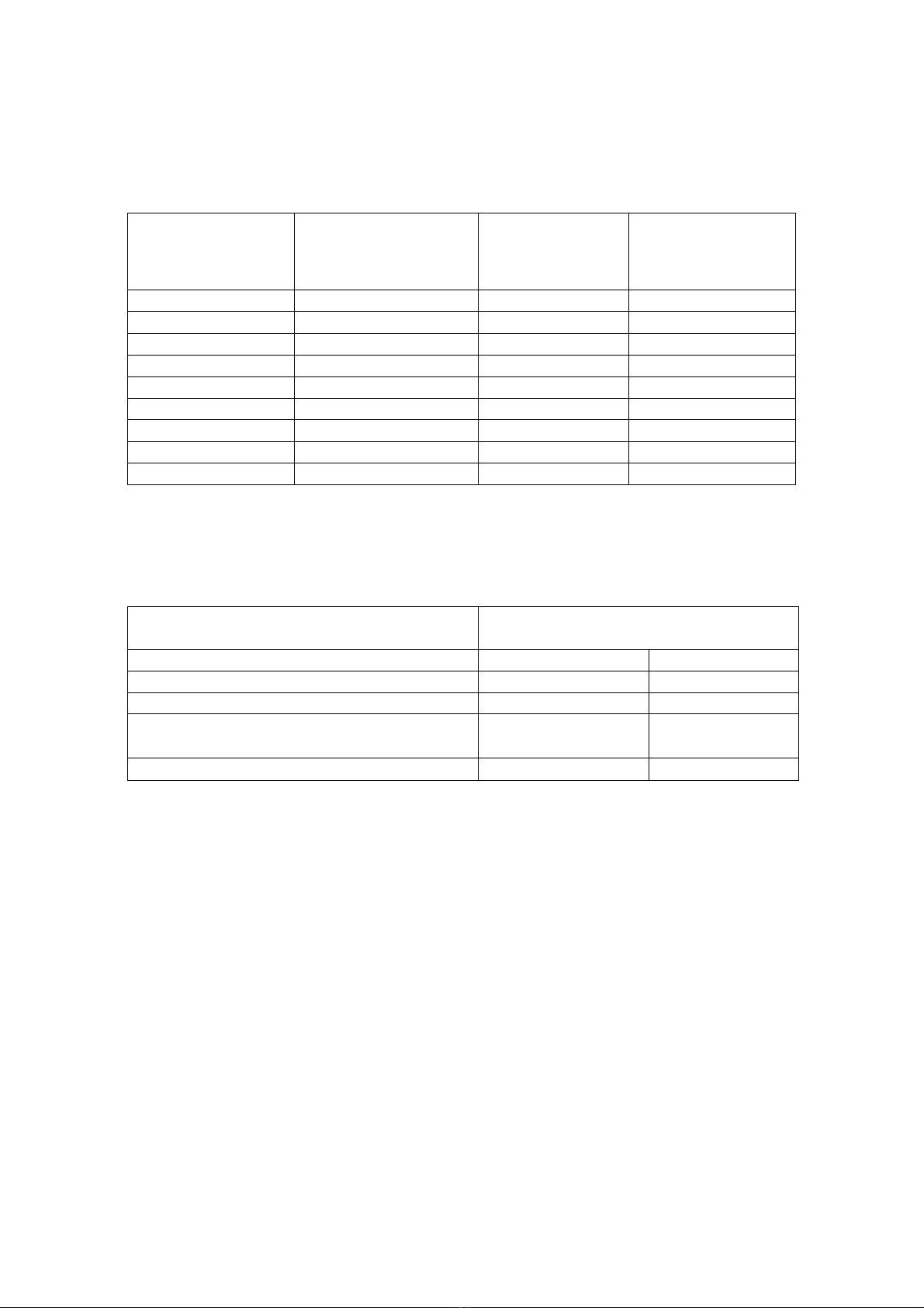
The table 2.4 - Correspondence of the position of micro switches on the back
panel of MT to different types of connected sensor devices.
Primary converter or input signal Position of corresponding micro switch
Upper (ON) lower
Thermoelectric converter 3 1,2,4
Direct current 1,2 3,4
Voltage of direct current 3 1,2,4
Thermo-converters of resistance
•double-wire connection circuit 3,4 1,2
•three-wire connection circuit 3,4 1,2
* For the MT version with variable configuration.
2.4 Error messages.
2.4.1.In case of any troubles or malfunctioning of MT on the main
display the error message is flashed. Possible errors, error messages, and
ways of their eliminations are provided in the table 2.5.

11
Table 2.5
Error code Malfunction Course Method of
elimination
“Err 0” Emergency condition of
the instrument
Malfunction of the
micro controller
Only in industrial
conditions
“Err 1” Emergency condition of
the instrument
Malfunction of the
micro controller
Only in industrial
conditions
“Err 2” Error in circuit
parameters
configurations
The network number
and messaging rate
with a computer is
set incorrectly
To set the network
number or messaging
rate with a computer
correctly when tuning
MT according to par.
3.2.1.2.16 and
3.2.1.2.17) of the
operator manual
“Err 4” Emergency condition of
the instrument
Malfunction of the
micro controller
Only in industrial
conditions
“Err 5” Rupture of all input
channels
When tuning MT all
input channels are
switched off,
incorrect MT
configurations.
Connect at least one
input channel when
tuning NT (see par.
3.2.1.2.2) of the
operator manual.
“-OU-” Variation of the signal
above the maximally
tolerable level of the
sub range
Input signal outside
the measuring sub
range
Provide for
correspondence of the
level of input signal to
sub range of
measurements
“-AL-” Variation of the signal
below the maximally
tolerable level of the
sub range
Input signal outside
the measuring sub
range or rupture of
the circuit of primary
converter.
Provide for
correspondence of the
level of input signal to
sub range of
measurements or
elimination of the
rupture of the circuit
of primary converter.
“----” Impossible to display a
parameter
Inconsistency of the
parameter value and
preset parameter
( see par.3.2.1.2 5) of
the operator Manual)
Decrease the
parameter “number of
digits after comma”
when tuning MT
" Err 0 ", " Err 1 ", " Err 4 " - error in internal memory of MT, the
cause is eliminated only in industrial conditions.
" Err 2 " - network number or speed of interchanging of the instrument
with the computer is incorrectly set.
" Err 5 " - there are no live channels.

12
Notes: In case of any errors with the codes “Err 0” … “Err 5” MT is
automatically assigned: number of the instrument – “0”, and the speed of
interchange – “9600”; after elimination of courses of malfunction, values of
these parameters are reinstated.
2.5. Marking and sealing
2.5.1. The marking corresponds to GOST 26828-86 Е, GOST
9181-74 Е, GOST 12.2.020-76 and drawing НКГЖ.405546.001-02СБ.
2.5.2. MT is sealed up by the representative of the QCD of the plant –
producer.
2.6. Packaging
2.6.1.Pacaging corresponds to GOST 23170-78E, GOST 9181-74 Еand
the drawing НКГЖ.405546.001-02УЧ and ensures complete safety of MT.

13
3. EMPLOYMENT OF ARTICLE ACCORDING TO PURPOSE
3.1. Preparation of the article for operation.
3.1.1. Safety measures instructions.
3.1.1.1. As to the method of protection of operators from electric
shocks MT corresponds to the class II according to GOST 12.2.007.0-75.
MT has a clamp of measuring earthing according to GOST 12.2.007.0-75.
Before the beginning of operation it is necessary to verify quality of earthing.
3.1.1.2. The primary converters are connected according to marking
when supply voltage is cut off.
3.1.1.3. When operating MT it is necessary to abide by requirements of
GOST 12.3.019-80, "Regulations of technical operation for electric devices of
consumers", "Regulations on the safety of operation of electric devices of
consumers " and "Rules of designing of electric devices. ПУЭ ", authorized by
Gosenergonadzor, it is also necessary to follow instructions on safety
regulations adopted by plants operating MT.
3.1.2. External inspection
3.1.2.1. When making external inspection, absence of mechanical
damage is established, correctness of marking, completeness is checked.
If there are any defects of coatings, affecting operation capacity of TM,
or discrepancies of completeness and marking, it is decided whether this MT
is possible to operate.
3.1.2.2. For each MT availability of the logbook with a mark of QCD is
cheked.
3.1.3. Assembly of an item.
3.1.3.1. For installation of MT it is necessary to have access to it from
the back side of the board. The sizes of the slot in the board should correspond
to item 2.2.17.
The order of installation:
- insert MT into the slot of a board;
- insert cramps into the body of MT;
- the front panel of MT is screwed to a board.
The electrical circuit of connections of MT with primary converters is
carried out via terminal blocks positioned on a back panel, and connections

14
with a web and commutation circuits - via РП 14-30 connector, according to
the figure A .1 of the Appendix A. The purpose of the contact connectors
Connections are performed in the form of cable ties.
Laying and terminating cables should meet the requirements acting
" Rules of designing of electric devices. ПУЭ ".
On the back panel there is a connector for hooking up of the computer
through the interface cable.
3.2. Employment of the artilce
3.2.1. Install MT on the instrumental board and lock safely.
3.2.2. Perform required connections of MT pursuant to
Appendixes A,Б.
3.2.3. Install micro-switches on the back panel in accordance to hooked
up thermoconverters and the table 2.4.( for versions of MT with variable
configurations)
3.2.4. If necessary - connect MT to the computer, load the
program of the configuration of MT, perform configuration of MT.

15
4. METHOD OF TESTING
4.1. MT is tested by bodies of the State Metrological Service or
Metrological Service of Consumers having the right of verification. The
requirements of verification, order, main stages of verification are stipulated
in ПР 50.2.006-94 "ГСИ. Verification of measuring facilities. Organisation
and procedure of verification" and in Recommendation "Methods of
verification МИ 2342-95".
Period of time between verifications is two years.
4.1.1. The basic reduced errors of measured values are determined
pursuant to the instructions provided in the item 5.5 of the recommendation
(for MT with input signals, corresponding configurations of verified MT).
4.1.2. Types and НСХ TR and TC for MT should correspond to the
ones provided in the present manual and meet the requirements of GOST
6651-94 and GOST Р8.585-2001 accordingly.
4.1.3. For tested MT, which HCX of the primary converter and ranges
(and the sub-ranges) of measurements correspond to those provided in the
recommendation, repeated points are indicated in the tables 5, 6 and 7 of the
recommendation.
Tested points of MT, with sub-ranges different from those provided in
the recommendation, are calculated pursuant to the item 5.5.1 of the
recommendation.
4.1.4. The basic reduced error of measured values, for the
configurations of MT with input electric signals in the form of voltage of
direct current, is determined in the points corresponding to 5, 25, 50, 75 and
95 % of the measurement range, by connecting a source of calibrated voltages
to the tested MT.
4.1.5. The basic reduced error of measured values for the MT
configurations with input electric signals in the form of direct current is
determined in verified points corresponding to 5,25.50,75 and 95 % of the
measurement range by connecting to the verified MT a source of calibrated
voltages.
4.1.6. For MT with input electric signals in the form of direct current of
0 … 5, 0 … 20 and 4 … 20 мА with root extracting dependence of measured
value of an input signal the basic reduced error is determined in the points
0,1; 1; 2; 3; 4; 5 мА - for range 0... 5 мА;
1; 5; 10; 15; 20 мА - for range 0... 20 мА;
4, 32; 8; 12; 16; 20 мА - for range 4... 20 мА.

16
True readings of the measured value At for the ranges of input signals
0... 5, 0…20 and 4... 20 мА are calculated from the formula (4.1), (4.2) and
(4.3) accordingly:
Аt = Амакс х√Iinput i (4.1)
√5
Аt = Амакс х√Iinput i (4.2) and
√20
Аt = Амакс х√Iinput i – 4 (4.3)
√16
Аt - True reading of measured value in the tested point;
Амакс - the upper limit of the range of measured value (is set during
configuration), the lower limit of the range of measured value is equal to 0;
Iinput i – the value of current in the input of the tested point;
5 мА, 20мА, 16 мА - ranges of input signals;
4 мА - lower limit of the range of an input signal for MT with
an input 4... 20 мА.
4.1.7. The basic reduced errors of measured values, determined from
the formula (5.1) of the recommendation should not exceed indicated in the
item 2.2.1 of the present operation manual.
4.1.8. Determination of the basic reduced error on the computer channel
is compared with determination of the basic reduced error of measured value.
The basic reduced error on the computer channel should not exceed the basic
reduced error of the measured value.
4.1.9. Determination of the basic error of the signalling system
operation.
4.1.9.1. Perform the configuration of MT for any type of an input
signal.
4.1.9.2. Set any values of two settings within the limits of measuring
range.
4.1.9.3. Perform the configuration of the logic of operation of all eight
relays in relation to programmed settings with allowance for possibilities of
opening of an input circuit.

17
4.1.9.4. Set a hysteresis on both settings.
4.1.9.5. Connect to clamps of relay channels of MT the indication
circuit of a closed /open conditions of channels (for example, circuits of light
emitting diodes power supply).
4.1.9.6. Change sequentially values of an input signal of MT from one
setting to another, make sure that all relays operate properly, both on
indication on the front panel of MT and on indicators connected to clumps of
channels.
4.1.9.7. The basic error of actuation of the signalling system should not
exceed the lowest digit of measured value for the following types of settings:
lower setting: U sett- signal is moderated;
Usett +Uhyst - signal is augmented;
upper setting: Usett - signal is augmented;
Usett - Uhyst - signal is moderated;
where Usett - value of settings;
Uhyst - value of hysteresis of setting.

18
5. TECHNICAL MAINTENANCE
5.1. Technical maintenance of MT is reduced to observance the
operating rules, stowage and transportation rules explained in the present
operation manual, to routine inspections, periodic checks and repair works.
5.2. The routine inspections are carried out in the order established at
the places of MT operation, but not less often then twice a year and include:
1) external examination;
2) inspection of holding power of communication lines of MT with
primary converters, absence of rapture of a grounding wire, holding power of
MT and grounding joint;
3) Functional test:
- self-calibration of MT;
- testing of electric resistance of insulation pursuant to the
Recommendation " The methods of control of MT 2342-95 ";
- testing of electric strength of insulation pursuant to the
Recommendation " The methods of control of MT 2342-95 ";
- testing of measuring precision of MT in points corresponding to 5, 50,
95 % of the range of measured values in accordance with the section 4 of the
present operation manual.
Under conditions of conducting a functional testing, when the
possibility of using of additional measuring aids is eliminated, MT is not
subject to inspection on precision of measuring. In this case only functioning
of MT is tested.
MT is considered functioning, if its readings roughly coincide with the
measured value.
5.3. Periodic testing of MT is performed not less often than once per
two years pursuant to the instructions, provided in the section 4 of the present
operation manual.
5.4. MT with faults which are beyond repair during routine
maintenance, or those ones that failed the periodic testing, are subject to
maintenance repair.
The repair of MT is made at the manufacturer’s enterprise under the
separate agreement.

19
6. STORAGE
6.1. The storage conditions for MT in transportation packing in a
warehouse of the manufacturer and consumer should correspond to conditions
of I GOST 15150-69.
Aggressive impurities should not be present in the air.
6.2. Disposition of MT in warehouses should ensure a free access to it.
6.3. MT should be stored on the racks.
6.4. Spacing interval between the walls, floor of a warehouse and MT
should be not less than 100 mm.
7. TRANSPORTATION
7.1. MT is transported by all types of transport in the covered
transportation vehicles. The attachment of containers in transportation
vehicles should be done according to the rules acting on the applicable types
of transport.
7.2. The conditions of transportation of MT should meet conditions 5
of GOST 15150-69 at the temperature of ambient air from minus 10 up to
+50°C with observance of protection measures from shocks and vibration.
7.3. MT should be transported packaged in parcels or piece by piece.
Transportation of MT in boxes should be performed in accordance with
the GOST 21929-76 requirements.

20
Appendix A
The electric diagram of MT 5132 connections
Connection of MT by the three-wire circuit
Connection of MT by the two-wire circuit
Connection of the thermoelectric couple
Connection of voltage source
Connection of current source
Figure A.1
GND
U
I
1
I
chann
1 2 3 4 5 6 7 8 9 0
c b a
1 2 3 4 1 2 3 4
1 2 3 4 1 2 3 4
1 2 3 4 1 2 3 4
1 2 3 4 1 2 3 4
Terminal blocks 1
series of 12 contacts
GND
U
I
GND
U
I
GND
U
I
II
chann
III
chann
IV
chann
Connector РП 14-30
5
2 6
3 7
4 8
GND
U
I
GND
U
I
GND
U
I
GND
U
I
V
канал
VI
канал
VII
канал
VIII
канал
K13
K1
K24
K1
2
Connector DB9 for
connection to a com
p
uter
I
U
GND
Rt
I
U
GND
Rt
I
U
GND
ТП
+
_
I
U
GND
Uin
_
+
I
U
GND
Iin
+
_
Table of contents


