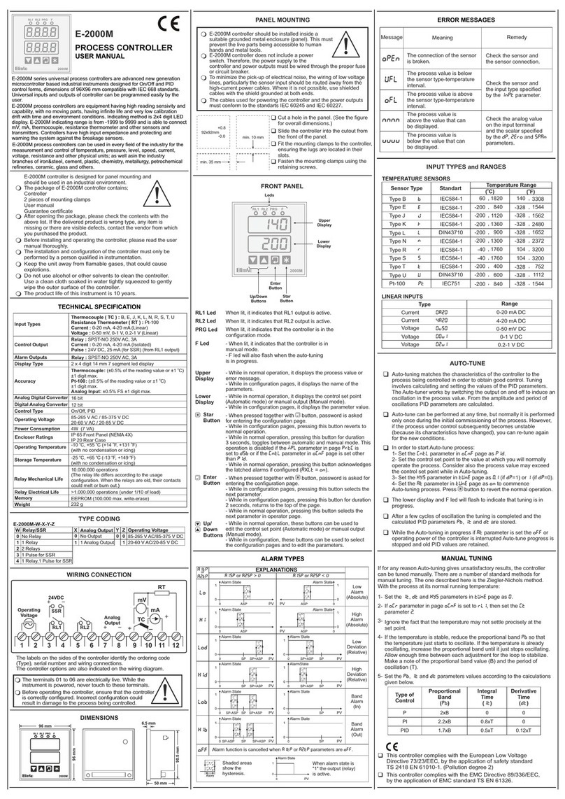
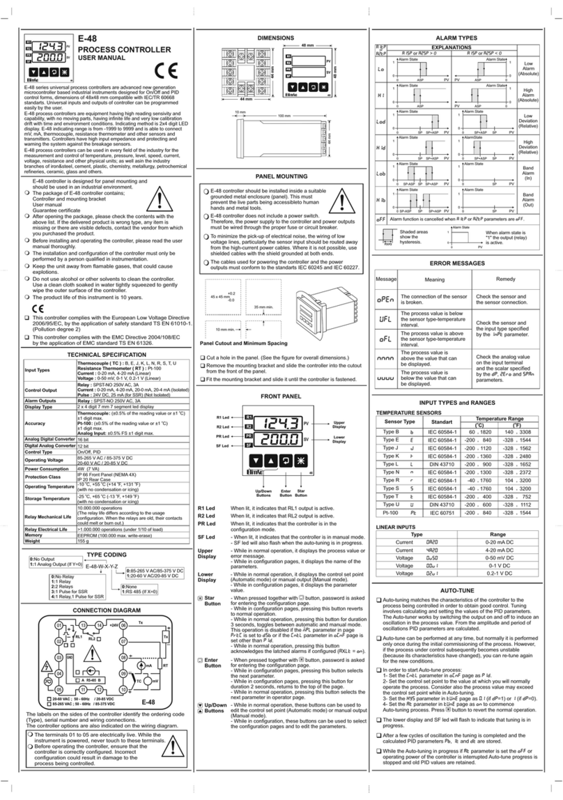
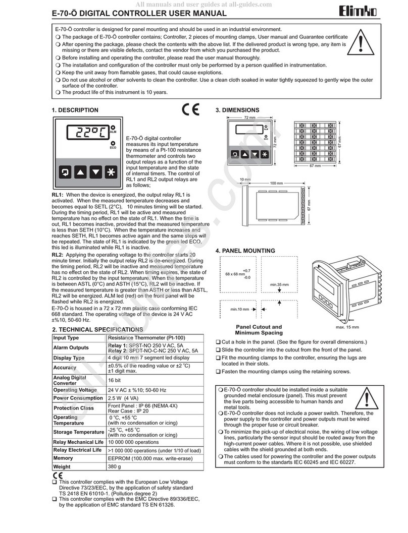
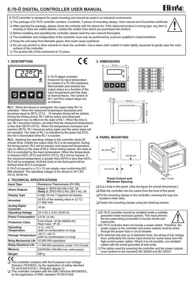
Elimko E-48 User manual

Elimko
KY-GEN-S-0923-0 1 / 33
GENERAL USER MANUAL
PROCESS CONTROLLERS
E-48
E-49
E-200
E-72
E-94
E-2000M

CONTENTS
1. DEFINITION
1.1. Front Panel Keys and Led Indicators
2. POWER ON AND CONTROL MODES
3. FRONT PANEL KEYS AND PROGRAMMING
3.1. Process Screen and Operation Parameters
3.2. Accessing Configuration Pages
3.3. General Configuration Page (GCNF)
3.4. Control Set Point Configuration (SETP)
3.5. Alarm Configuration Page (ACNF)
3.6. Output Configuration Page (OCNF)
3.7. PID Configuration Page (TUNE)
3.8. Security Configuration Page (PRTC)
4. CONFIGURATION STEPS AND APPLICATIONS
4.1. Use as a Single Output PID Controller
4.2. Use as a Dual Output PID Controller (HEAT/COOL)
4.3. Valve Control without Feedback (Floating Control)
4.4. Feedback Valve Control (Servo Feedback)
5. MODBUS COMMUNICATION INFORMATION
3
3
5
5
7
9
10
13
16
18
21
24
26
27
27
28
28
29
Elimko
2 / 33
. . . . . . . . . . . . . . . . . . . . . . . . . . . . . . . . . . . . . . . . . . . . . . . .
. . . . . . . . . . . . . . . . . . . . . . . . . . .
. . . . . . . . . . . . . . . . . . . . . . . . . . . .
. . . . . . . . . . . . . . . . . . . . .
. . . . . . . . . . . . . . . . . . . . . .
. . . . . . . . . . . . . . . . . . . . . . . . . . . . . . . .
. . . . . . . . . . . . . . . . . . . . . . . . . . . .
. . . . . . . . . . . . . . . . . . . . . . . . . .
. . . . . . . . . . . . . . . . . . . . . . . . . . . . . .
. . . . . . . . . . . . . . . . . . . . . . . . . . . . . .
. . . . . . . . . . . . . . . . . . . . . . . . . . . . . . . . .
. . . . . . . . . . . . . . . . . . . . . . . . . . . .
. . . . . . . . . . . . . . . . . . .
. . . . . . . . . . . . . . . . . . . . . . . . . .
. . . . . . . . . . . . . . . .
. . . . . . . . . . . . . . . . .
. . . . . . . . . . . . . . . . . . . . . . .
. . . . . . . . . . . . . . . . . . . . .
KY-GEN-S-0923-0

Elimko
3 / 33KY-GEN-S-0923-0
1. INTRODUCTION
This user manual is released for
E-48, E-49, E-72, E-94, E-200, E-2000M
series controllers and contains detailed information about common features and
common parameter explanations. Depending on the controller, some parameters
may not be exist because of different hardware and IO properties.
Please refer to the quick user manual shipped with the controller for device specific
dimension, panel mounting, connection diagram, and technical specification.
These universal industrial process controllers have ON/OFF, single PID, Heat/Cool
PID, feedback valve control, and floating valve control capabilities which are
powered by new generation micro controllers. Universal inputs (T/C, R/T, mV, mA)
and outputs are easily configurable with front panel keys.
All controllers have two 4 digit segment displays on which measurement and set
values in the range of -1999 to 9999 are displayed.
1.1 Front Panel Keys ve LED Indicators
LED Indicators
Down Up Exit
(Returns to the process screen)
Enter
Lights when Relay 1 is ON.
Lights when Relay 2 is ON.
Lights when Relay 3 is ON.
Lights when Relay 4 is ON.
Lights in programming mode.
Lights in Manual control mode.
Flashes during auto tuning of PID.
Upper
Display
Lower
Display
Some LED indicators may not be
exist depending on the controller
model.
Configuration Access
8.8.8.8.
8.8.8.8.1.2.9.2
1.2.2.2
R1
R2
R3
R4
PR
MN

Elimko
4 / 33KY-GEN-S-0923-0
During first couple of seconds after power on, all segments and LED indicators light.
After that, upper display shows controller model and lower display shows firmware
version for a duration of 3 seconds and eventually Process Screen are displayed.
Consecutive pressing of 3 key toggles between Process Screen and several
operation parameter screens. Pressing key returns to the Process Screen.4
The controllers have two control modes as Automatic and Manual. To change the
control mode, 4 key is pressed for at least 3 seconds at the Process Screen. (Only
functional when ocnfaMNPR (Manual Mod Selection) = ENB).
User can make control operation inactive by selecting ocnfactyp (Control Type) =
NONE and by this way, the controller can be used as a process display and alarm
device.
While in Automatic Control Mode, control output is calculated by the controller
where as in Manual Control Mode, then control output is manually entered by the
operator.
Process Variable (PV) is shown in Upper Display at the Process Screen.
Lower Display shows the control set point (SV) in Automatic Control Mode and
pressing 12 keys changes the set value. In Manual Control Mode, the lower display
shows manual output value and in the same way, the operator can adjust this value
by pressing 12 keys. MN LED lights in Manual Control Mode.
2. POWER ON AND CONTROL MODES
Manual Control Mode
200.0
85.3
Process
Screen
Process Value
Output Value
8888
8888
Power On
A1SP
100.0
A2SP
200.0
A1TP OFF≠A2TP OFF≠
A3SP
300.0
A3TP OFF≠
A4SP
400.0
A4TP OFF≠
Alarm Set Points
3 3 3 3 3
4
Automatic Control Mode
200.0
200.0
Process
Screen
Process Value
Set Value
8888
8888
Power On
OUT
90.0
PSP
185.0
A1SP
100.0
A2SP
200.0
SPSR PRFL≠A1TP OFF≠A2TP OFF≠
A3SP
300.0
A3TP OFF≠
A4SP
400.0
A4TP OFF≠
Output
Value
Progressive
Set
Value
Alarm Set Points
4
3 3 3 3 3 3 3
Automatic Control Mode while a profile is running
200.0
200.0
Process
Screen
Proses Value
Profile Set Value
8888
8888
Power On
a-1
2.0
OUT
90.0
Step
Remaining
Time
Output
Value Alarm Set Points
A1SP
100.0
A2SP
200.0
A1TP OFF≠A2TP OFF≠
A3SP
300.0
A3TP OFF≠
A4SP
400.0
A4TP OFF≠
3 3 3 3 3 3
4
3

Elimko
5 / 33KY-GEN-S-0923-0
1) Pressing 4 key returns to the Process Screen.
2) Pressing 3 key accesses to next available screen.
3) 12 keys are used to adjust parameter values.
4) In order to reach and adjust a parameter, the operator needs to know in which page
the parameter is located. After that, pressing 43 keys together shows Cod entry
screen and 12 keys are used to enter Security Code. After entering Security Code,
pressing 3 key shows PAGE screen. In this screen, 12 keys selects the page to be
accessed and pressing 3 key enters to the selected page. At this stage, consecutive
pressing of 3 key accesses to next available parameter for adjusting. After reaching
to the parameter to be changed, 12 keys are used to adjust the parameter to
required value. While in the pages, pressing 3 key more than 2 seconds changes
screen to PAGE selection screen again.
5) Other key functions are explained in relevant parameter explanation in details.
Please see parameter explanation sections.
6) Some parameters may become invisible depending on other relevant
configurations.
7) Whole parameter set are depicted in Figure 3.1. Depending on the controller
model, some parameters may not be exist.
3. FRONT PANEL KEYS AND PROGRAMMING

Elimko
6 / 33KY-GEN-S-0923-0
3. FRONT PANEL KEYS AND PROGRAMMING
Şekil 3.1. Configuration Pages and Parameters
COD
0
PAGE
GCNF
PAGE
SETP
PAGE
OCNF
PAGE
TUNE
PAGE
PRTC
SPSR
INT
SCOD
10
INP1
K
SCLO
0.0
SCHI
400.0
OFST
0.0
UNIT
°C
FLTR
2
SNBR
HI
S2LO
0.0
S2HI
400.0
INP2
4A20
PRTY
EVEN
ADRS
1
BAUD
38.4
S2BR
LO
SPLL
-199.9
SPHL
999.9
SPRR
OFF
PONC
0
TRLL
0.0
TRHL
400.0
SRVL
0.0
SRVH
0.0
CTYP
SCO
CFRM
REV
MNPR
DSB
TRTM
100
DBND
0.5
OLL
0.0
CPRD
2
OHL
100.0
OMR
50.0
AT
OFF
PID
STD
PB-1
20.0
ITH
28
DTH
7
ITC
28
DTC
7
HYS
20.0
PB-2
20.0
DPRL
5
FCST
OFF
APRL
2
DP
1
PAGE
ACNF
RL1D
CO-1
AO1D
CO-1
AO1R
4-20
AO2R
4-20
AO2D
CO-2
RL2D
AL-2
RL3D
AL-3
RL4D
AL-4
T-1
2.0
S-1
50.0
SET1
0.1
SET2
0.2
SET3
0.3
SET4
0.4
S-2
50.0
S-3
100.0
T-2
2.0
T-3
2.0
A1TP
LO
A1SP
100.0
A1HY
0.5
A1LT
DSB
A2TP
HI
A2SP
100.0
A2HY
0.5
A2LT
DSB
A3TP
LO
A3SP
100.0
A3HY
0.5
A3LT
DSB
A4TP
HI
A4SP
100.0
A4HY
0.5
A4LT
DSB
Security
Code
General
Configuration
Set Point
Configuration
Output
Configuration
PID
Configuration
Security
Configuration
Alarm
Configuration
12
43 3
3 3 3 3 3 3
12 12 12 12
3
3
3
3
3
3
12

Elimko
7 / 33KY-GEN-S-0923-0
3.1. Process Screen and Operation Parameters
200.1
200.0 Process Screen Always
EU
Screen Definition Min Access
MaxUnit
Process Screen is the power on screen of the controllers and pressing 4 key
returns to this screen anytime. In this screen, upper display always shows process
value. Lower display shows either control set point or manual output value
depending on selected control mode. In automatic mode, control set point can be
adjusted between SPLL..SPHL and in manual control mode, the manual output
value can be adjusted between OLL..OHL using 12 keys. In manual control mode,
MN LED lights.
In Automatic Control Mode, if SETPaSPSR (Control Set Point Source) = PRFL and the
profile is not running, lower display shows PRFL message. After running the profile,
depending on the configured profile a changing and non adjustable control set point
is followed. Please see SETP configuration page for detailed profile configuration.
4 and 2 : Runs the profile.
4 and 1 : Stops the profile.
1 : Suspends the profile. Lower display flashes.
2 : Rerun the suspended profile.
In Automatic Control Mode, if SETPaSPSR (Control Set Point Source) = DINP, lower
display shows one of the digital input selectable control set point (SET1, SET2, SET3,
SET4) and adjustment is not allowed. Please see SETP configuration page for
detailed usage information.
In order to change control mode, first Process Screen is accessed by pressing 4
key and than 4 key is pressed and hold for at least 3 seconds . Alternatively,
Manuel Control Mode can be activated digitally by stimulating 1. digital input if
available. If the stimulation is removed, the controller returns to the automatic
control mode again. Mode selection is available only if OCNFaCTYP (Control Type) is
not NONE and OCNF aMNPR (Manuel Mode Selection) is ENB.
In Manual Control Mode, if OCNFaCTYP (Control Type) is BND (floating valve control)
, instead of a numeric output percentage, following messages are shown.
STP : None of the valve control output is active. Shown when no key is
pressed
OPN : Valve open output is active . 2 key activates valve open output.
CLS : Valve close output is active. 1 key activates valve close output.
aaa

Elimko
9 / 33KY-GEN-S-0923-0
3.2. Accessing Configuration Pages
In order to access configuration pages, the operator needs to reach security Cod
entry screen by pressing 4 and 3 keys together as the first step. Factory settings of
Security Code is 10.
Security Code Entry Always
0 9999
Security code is entered using 1 and 2 keys and 3 key is pressed to reach PAGE
selection screen. In case of a wrong password entry, only PRTCaDPRL (Parameter
Access Level) and PRTCaAPRL (Parameter Setting Level) limitted access and
setting rights become available. In order to get full access and setting rights, the
correct code must be entered. In order to reset Security Code, during first 25
seconds after power on, 12 ve 4 keys can be pressed together and hold for a
second. After that, Security code checking will be disabled at the following try and
the operator will be able to enter configuration with full rights in order to reconfigure
PRTCaSCOD (Security Code).
Page Selection Screen Always
After selecting the configuration page by pressing 1 and 2 keys, pressing 3 key
enters to the selected page and first parameter of the page appears on the screen.
After that consecutive pressing of 3 key passes to next parameter. After the last
parameter is reached, the screen returns to the Page Selection Screen again.
Pressing and holding 3 key for 2 seconds also reverts the screen to Page Selection
again before reaching the last parameter. 1 and 2 keys adjust parameters to
required value.
Following pages are available for the configuration.
(0) GCNF : Inputs, scales and MODBUS communication parameters.
SETP : Control set point options, set limits, profil configuration.(1)
ACNF : Alarm configuration.(2)
(3) OCNF : Output configuration, output limits, valve control parameters
TUNE : PID parameters and autotuning (4)
PRTC : Security Code (SCOD), access and setting rights, factory settings.(5)
Pressing 4 keys returns to the Process Screen.
COD
0
PAGE
GCNF
Screen Definition Min AccessMaxUnit

Elimko
8 / 33KY-GEN-S-0923-0
aaa
When an error is detected in process value measurement (Analog Input 1) or
measurement value is non displayable, upper display shows one of the following
messages.
OPEN : Sensor broken or not connected.
OFL : Input signal is above sensor limits.
UFL : Input singnal is below sensor limits.
^^^^ : Value is bigger than 9999.
vvvv : Value is lower than -1999.
When a lock parameter enabled alarm (A1LT, A2LT, A3LT, A4LT) is detected, 4 key
is pressed in order to release the locked alarm, if the alarm condition is not still exist.
out
65.0 Automatic Output Value Automatic Mode
OLL OHL %
A-x
19.8 Remaining Step Time ( X = 1, 2, 3) Profile running
0 999.9 minute
Remaining step time and step number is displayed while profile is running (A-1, A-2,
A-3).
In Automatic Control Mode, controller calculated output value is shown and can
not be adjusted. In Heat/Cool control type, negative values indicates cooling.
3.1. Process Screen and Operation Parameters
In Automatic Control Mode, Progressive Control Set Point is followed. For detail
explanation of this parameter, please see SETPa SPRR (Control Set Point
Ramp Rate).
PSP
200.0
AxSP
200.0
Progressive Control Set Point
Alarm Set Points ( x = 1, 2, 3, 4)
Spsr ≠ PRFl
Alarm Type is not OFF
SPLL SPHL
Alarm set points are followed and adjusted. For the Alarm Configuration, please
see (A1SP, A2SP, A3SP, A4SP) in ACNF Configuration Page.
-199.9 999.9
Screen Definition Min AccessMaxUnit

Elimko
10 / 33KY-GEN-S-0923-0
3.3. General Configuration Page (GCNF)
Display format of all parameters with EU unit(Analog Input 1 Unit) .
0 : 0 1 : 0.0 2 : 0.00 3 : 0.000
*If INP1 is thermocouple or resistance thermometer, upper limit for this
parameter is 1.
Decimal Point Always
DP
1
This scale is used to derive process value
from the input signal when INP1 (Analog
Input 1 Type) is a linear signal such as (mA,
mV, V). It is a linear scale and defines how
measured value will change over the entire
range of input signal. SCLO can be bigger
than SCHI.
Analog Input 1 Linear
Scale Lower Value
Analog Input 1 Linear
Scale Upper Value
Analog Input 1
(mA,mV, V)
Analog Input 1
(mA,mV, V)
-199.9
-199.9
999.9
999.9
EU
EU
SCLO
0.0
SCHI
400.0
SCHI
PV (Process Value)
Input
Low
Input
High
Input
Signal
SCLO
Analog Input 1 Type Always
INP1
K
(11)
(12)
0A20 : 0-20 mA (Linear)
4A20 : 4-20 mA (Linear)
(13) 0V50 : 0-50 mV (Linear)
(14) 0.0V1 : 0-1 V (Linear)
0.2V1 : 0.2-1V (Linear)
(15)
(0)
(1)
(2)
(3)
(4)
(5)
(6)
(7)
(8)
(9)
(10)
B: Type B Thermocouple IEC 60584-1 60 1820 °C
No Input Type Standard Min. Max.
IEC 60584-1
IEC 60584-1
IEC 60584-1
IEC 60584-1
IEC 60584-1
IEC 60584-1
IEC 60584-1
E: Type E Thermocouple
J: Type J Thermocouple
K: Type K Thermocouple
L: Type L Thermocouple
N: Type N Thermocouple
R: Type R Thermocouple
S: Type S Thermocouple
T: Type T Thermocouple
U: Type U Thermocouple
PT: Pt-100 Resistance Thermometer
DIN 43710
DIN 43710
IEC 60751
-200 840 °C
-200 1120 °C
-200 1360 °C
-200 900 °C
-200 1300 °C
-40
1760 °C
-40 1760 °C
-200 400 °C
-200 600 °C
-200 840 °C
0 3
Screen Definition Min AccessMaxUnit

Elimko
3.3. General Configuration Page (GCNF)
UNIT
°C Temperature Unit Analog Input 1
Temperature Sensor
*C *F
This parameter is monitored when INP1 (Analog Input 1 Type) is selected as
Thermocouple or Resistance Thermometer.
OFST
0.0 Analog Input 1 Offset Value Always
-100.0 100.0 EU
OFST value is directly added to the process value of Analog Input 1.
Analog Input 1 Process Value = Analog Input 1 Measurement Value + OFST
FLTR
2Analog Input 1 Filter 115 second Always
It is the moving average time for the Analog Input 1 process value. The
measurement refresh time is 500 ms. For example, selecting 5 indicates that the
last 10 measurements will be averaged.
SNBR
HI
Analog Input 1
Sensor Broken Behaviour
Always
LO HI
It determines the measurement value when the Analog Input 1 sensor is detected
as broken sensor condition. Sensor break cannot be detected at 0-20 mA inputs.
When a broken sensor condition is detected, Analog Input 1 Process Value is
adjusted according to the selected value as follows. OPEN message is displayed on
the screen.
(0) LO : Process Value is equal to -32000.
HI : Process Value is equal to 32000.(1)
Analog Input 2 Type Devices have
2 Analog Inputs
0-20 4-20
(0) 0-20 : 0-20 mA
4-20 : 4-20 mA(1)
Screen Definition Min AccessMax Unit
11 / 33
INP2
4-20
KY-GEN-S-0923-0

Elimko
3.3. General Configuration Page (GCNF)
Modbus Address Devices with RS-485
Communication
1 127
It determines the measurement value when the Analog Input 2 Sensor detects a
broken sensor condition. Sensor break cannot be detected at 0-20 mA inputs.
When a broken sensor condition is detected, Analog Input 2 Measurement Value is
adjusted according to the selected value as follows.
(0) LO : It is equal to S2LO.
HI : It is equal to S2HI.(1)
Modbus Baud Rate Devices with RS-485
Communication
(0) 4.8 kbaud
9.6 kbaud(1)
19.2 kbaud(2)
38.4 kbaud(3)
Modbus Parity Devices with RS-485
Communication
(0) NONE : No Parity
ODD : Odd Parity(1)
EVEN : Even Parity(2)
Analog Input 2
Sensor Broken Behaviour
Always
LO HI
Analog Input 2
Linear Scale Upper Value
-199.9 999.9
Analog Input 2
Linear Scale Lower Value
-199.9 999.9 Devices have
2 Analog Inputs
EU
Devices have
2 Analog Inputs
EU
This scale is used to derive measurument
value from the Analog Input 2 signal. It is a
linear scale and defines how measured
value will change over the entire range of
input signal. S2LO can be bigger than S2HI.
Screen Defintion Min AccessMax Unit
12 / 33
S2LO
0.0
S2HI
400.0
S2BR
LO
ADRS
1
BAUD
38.4
PRTY
EVEN
S2HI
Measurement Value
Input
Low
Input
High
Input
Signal
S2LO
KY-GEN-S-0923-0

Elimko
3.4. Control Set Point Configuration (SETP)
Control Set Point Lower Limit -199.9 SPHL EU
Control Set Point Upper Limit SPLL 999.9 EU
Control Set Point Source Always
Screen Definition Min AccessMax Unit
Control Set Point Ramping Rate Spsr ≠ PRFl
0.0 60.0
EU
minute
After a change to the control set point, the rate of progression from the current set
point to the new set point is determined. This rate specifies the amount of change in
the control set point per minute.This behavior of the set point is defined as the
Process Set Point (PSP) running in the background. If SETPaSPRR (Control Set
Point Ramping Rate) is turned off, this feature is disabled. For example, if this
parameter is set to 10.0, and the set point is changed from 100.0 to 200.0, the
running set point will reach the newly set point in 10 minutes.
(200.0-100.0)/10.0=10.0 minutes
13 / 33
Always
Always
SPSR
INT
SPRR
OFF
SPLL
-199.9
SPHL
999.9
(0) INT : Internal. Adjusted using front panel keys
PRFL : Defined by Profile Parameters(1)
E/T : Defined by Analog Input 2 measurement(2)
DINP : Selected by Digital Inputs (Available only in devices with digital (3)
inputs.)
KY-GEN-S-0923-0

Elimko
3.4. Control Set Point Configuration (SETP)
Screen Definition Min AccessMax Unit
Step Time (X = 1 .. 3) SPSR = PRFL
0 999.9 min
Step Set Value (X = 1 .. 3) SPSR = PRFLSPLL SPHL EU
These are the parameters that needs to be set when the control set point source
SPSR is set to PRFL. For each step, a time (T-1, T-2, T-3) and a corresponding set
point (S-1, S-2, S-3) are defined. The profile is created by progressing to the set
points at the specified times.
14 / 33
If the set point is entered the same as the previous step's set point, the profile
continues horizontally. If the step duration is set to OFF, the step is canceled, and
the process proceeds to the next step.
The operations of Profile Start/Stop and Pause/Resume are performed using the
front panel buttons while in the process screen.
4 ve 2 : Starts Profile.
4 ve 1 : Stops Profile.
1 : Pauses Profile. The lower display blinks .
2 : Resumes Profile.
Profile operations can also be controlled using digital inputs. When Digital Input 2 is
triggered, the profile starts. When the trigger is removed, the profile stops. While the
profile is running, if Digital Input 3 is triggered, the profile is paused. When the
trigger is removed, the profile resumes.
S-1
Time (min)
Set (EU)
S-2
S-3
T-1 T-2 T-3
Profile
Start
Profile
End
PV
Control Outputs are active
When the profile doesn’t work, the control outputs are not active.
T-x
2.0
S-x
50.0
KY-GEN-S-0923-0

Elimko
3.4. Control Set Point Configuration (SETP)
Four control set point (SET1, SET2, SET3,
SET4) selectable with Digital Input 2 and 3
can be adjusted when SPSR is selected as
DINP.
Screen Definition Min AccessMax Unit
Set Values are selected with
Digital Inputs (X = 1 .. 4) SPSR = DINPSPLL SPHL EU
15 / 33
2
3
Set1
OFF
Set2 Set3 Set4
Digital
Input
OFF
OFF
ON
ON
OFF
ON
ON
SETx
0.1
KY-GEN-S-0923-0

Elimko
3.5. Alarm Configuration Page (ACNF)
(0) OFF : Off
(1) LO : Low Alarm a If the process value is below the alarm set point, the alarm
becomes active. The alarm deactivates when the process value rises above the alarm
set point by the amount of hysteresis.
(2) HI : High Alarm a If the process value is above the alarm set point, the alarm
becomes active. The alarm deactivates when the process value drops below the
alarm set point by the amount of hysteresis.
(3) LOD : Low Deviation a It is the same as the Low Alarm. The alarm set point is
calculated by adding the control set point to the alarm set point (Set = Control Set +
Alarm Set).
(4) HID : High Deviation a It is the same as the High Alarm. The alarm set point is
calculated by adding the control set point to the alarm set point (Set = Control Set +
Alarm Set).
(5) LOB : In Band Alarm a The alarm is active when the PV is inside the band
(6) HIB : Out Band Alarm a The alarm is active when the PV is outside the band
Alarm Types (x = 1..4)
(A1TP, A2TP, A3TP, A4TP)Always
Screen Definition Min AccessMax Unit
Alarm Set Points (x = 1..4)
(A1SP, A2SP, A3SP, A4SP)AxTP ≠ OFF
SPLL SPHL EU
Alarm Hysteresises (x = 1..4)
(A1HY, A2HY, A3HY, A4HY)AxTP ≠ OFF
0.0 999.9 EU
Alarm Locks (x = 1..4)
(A1LT, A2LT, A3LT, A4LT)AxTP ≠ OFF
DSB ENB
(0) DSB : Alarm lock is not active.
ENB : Alarm lock is active.(1)
If ENB is selected, once an alarm is triggered, it will continue to be active until
manually acknowledged using the front panel keys, even if the alarm condition is
not exsist. To unlock alarms that are in a locked state, you should press the 4 button
while in the process screen. If the alarm is no longer active, pressing this button will
release the alarm.
Four alarms are defined in the device. Alarm Type, Set Value, Hysteresis and Alarm
Lock paremeters can be set for each alarms. The alarm singnals can be assigned to
required relays available on the device.
LOB ve HIB Alarm Band
Control Set Value + Alarm SetControl Set Value - Alarm Set
AxTP
LO
AxSP
100.0
AxHY
0.5
AxLT
DSB
16 / 33KY-GEN-S-0923-0

Elimko
3.5. Alarm Configuration Page (ACNF)
SP : Control Set Value
PV : Process Value
17 / 33
EXPLANATION
Not active when set to OFF.
Axtp
HID
High
Deviation
LOB
In Band
Alarm
HIB
Out Band
Alarm
LOD
Low
Deviation
HI
High
Alarm
ON
AxSP
OFF
0
AxHY
Alarm
PV
ON
SP + AxSP
OFF
0
AxHY
Alarm
PV
ON
SP + AxSP
OFF
0
AxHY
Alarm
PV
ON
SP - AxSP
OFF
0
AxHY
Alarm
PV
SP + AxSP
AxHY
ON
SP - AxSP
OFF
0
AxHY
Alarm
PV
SP + AxSP
AxHY
OFF
ON
AxSP
PV
OFF
0
AxHY
Alarm
LO
Low
Alarm
KY-GEN-S-0923-0

(0) DSB : The user can not activate the Manual Mode
ENB : The user can activate the Manual Mode(1)
Elimko
3.6. Output Configuration Page (OCNF)
(0) None : Off
SCO : Single Control Output (+) Heat(1)
DCO : Double Control Output (+ / -) Heat /Cool(2)
BND : Floating Valve Control(3)
PFB : Feedback Controlled Valve Control (Available only in the devices (4)
with servo feedback input.)
Screen Definition Min AccessMax Unit
Control Type Always
Control Form CTYP ≠ NONE
REV
DIR
It determines control form
(0) DIR : If process value is higher than set value, the output increases
(Example: Cooling Element).
REV : If process value is higher than set value, the output decreases(1)
(Example: Heating Element).
Control Period CTYP ≠ NONE
1250 second
It is the refresh time of the PID control output. This parameter also determines the
PWM period for PID control done by a relay output.
Manual Mode Selection CTYP ≠ NONE
DSB ENB
Floating Control Valve
Travel Time CTYP = BND
10 2500 second
The transition time from fully open to fully closed position for the floating valves
should be entered in seconds.
Dead Band CTYP ≠ NONE
0.1 25.0 %
When CTYP is set to SCO or DCO, it determines the minimum value for the output
signal. The output is not activated for output values below this threshold.
When CTYP is set to PFB or BND, the valve will not be moved if the difference
between the required valve position and the current valve position is less than this
value.
CTYP
SCO
CFRM
REV
CPRD
2
MNPR
DSB
TRTM
100
DBND
0.5
18 / 33KY-GEN-S-0923-0

Elimko
19 / 33KY-GEN-S-0923-0
3.6. Output Configuration Page (OCNF)
When TUNEaITH (Integral Time +) parameter is set to zero (integral is not active),
it is added to the output value and determines the output value when the process
value is equal to the control setpoint.
Control Output Upper Limit CTYP ≠ NONE
OLL 100.0 %
Control Output Manual Reset CTYP ≠ NONE
OLL OHL %
(0) It operates with the settings at the moment of power off.
Turns on in automatic mode.(1)
Turns on in automatic mode. Integral Value = 0.(2)
Turns on in manual mode.(3)
Turns on in manual mode. Output Value = 0.(4)
PID Power On Behavior Always
Retransmission Scale Lower Value -199.9 TRHL EU
TRLL 999.9 EU
Control Output Lower Limit CTYP ≠ NONE
0.0* OHL %
* CTYP = DCO, the lower value that can be set is -100.0. Negative values indicate
cooling.
Screen Definition Min. AccessMax. Unit
The process value and control setpoint can be output as current or voltage via the
analog outputs on the device. This process is called Retransmission. TRLL and
TRHL determine the retransmission scale. By setting the parameters AO1D and AO2D
to PVTR, process value retransmission from the related output is activated.
Similarly, AO1D and AO2D parameters are set to SPTR and control setpoint
retransmission is activated from the related output.
Always
Always
OHL
100.0
OMR
50.0
PONC
0
TRLL
0.0
TRHL
400.0
OLL
0.0
Retransmission Scale Upper Value

Elimko
20 / 33KY-GEN-S-0923-0
3.6. Output Configuration Page (OCNF)
Parameters that determine the output ranges of Analog Outputs (AO1R, AO2R).
Current Outputs: Voltage Outputs:
(0) (0) 0-20 : 0-20 mA 0-10 : 0-10 V
20-0 : 20-0 mA 10-0 : 10-0 V(1) (1)
(2) (2) 4-20 : 4-20 mA 2-10 : 2-10 V
(3) (3) 20-4 : 20-4 mA 10-2 : 10-2 V
Analog Output Types (x = 1, 2)Always
Feedback Valve
Fully-Closed Position
SRVL and SRVH are calibration values for fully closed and fully open position of the
valve with feedback. While in these menus, the valve is set to fully closed or fully
open position depending on the parameter set using the 1 and 2 keys and the
value is saved by pressing the 4 and 1 keys. Valve Open output (CO-1) and Valve
Close output (CO-2) must be directed to the control relays by using RLxD
parameters before setting.
Feedback Valve
Fully-Open Position
Functions of Analog Outputs (x = 1, 2)
Always
Parameters that determine the function of analog outputs (AO1D, AO2D).
(0) CO-1 : PID + signal (Heating), Conversion Scale: 0 -100 %
CO-2 : PID - signal (Cooling), Conversion Scale: 0 -100 %(1)
PVTR : Analog Input 1 Retransmission, Conversion Scale: TRLL - TRHL(2)
SPTR : Control Set Point Retransmission, Conversion Scale: TRLL - TRHL(3)
Relay Functions (x = 1..4 Relasy)
Always
Parameters that determine the functions of the relays in the device.
(RL1D, RL2D, RL3D, RL4D)
(0) (4) CO-1 : PID + signal (Heating) AL-1 : Alarm 1
CO-2 : PID - signal (Cooling) AL-2 : Alarm 2(1) (5)
DO-1 : On-Off + signal (Heating) AL-3 : Alarm 3(2) (6)
DO-2 : On-Off - signal (Cooling) AL-4 : Alarm 4(3) (7)
Depending on the device type, some parameters may not be available on the
device.
CTYP = PFB
CTYP = PFB
AOxR
4-20
SRVL
0.0
SRVH
0.0
AOxD
CO-1
RLxD
CO-1
Screen Definition Min. Access
Max. Unit
Other manuals for E-48
1
This manual suits for next models
5
Table of contents
Other Elimko Controllers manuals