ELITechGroup CYTOPRO 7622 Instructions for use
!
!
!
!
!
!
!
!
!
!
!
!
!
!
!
!
!
!
!
!
!
!
!
!
!
!
!
!
!
!
!
!
!
!
!
!
!
!
!
!
!
!
!
!
!
!
CYTOPRO®(
(
CYTOCENTRIFUGE(
applications((
manual(
Model(7622(
!

CYTOPRO®
CYTOCENTRIFUGE
Model 7622
Applications Manual
57-2003-01B

2
©2013 ELITechGroup Inc. All rights reserved. Printed in the United States of America. No
part of this publication may be reproduced, transmitted, transcribed, stored in a retrieval
system, or translated into any language (human or computer) in any form, or by any means
whatsoever, without the prior express written permission of ELITechGroup Inc.
Wescor, Aerospray and Cytopro are trademarks of ELITechGroup Inc.
Other trade names used in this manual are trademarks of their respective owners, used here
for information only.
ELITechGroup Inc. makes no express or implied warranty regarding this manual, its quality,
performance, or appropriate use regarding any type of specific procedure. Elitech Group
may modify this manual without notice and without implying any obligation or liability on
the part of the company.
Manufactured in the United States of America by:
ELITechGroup Inc.
370 West 1700 South
Logan, Utah 84321-8212 USA

3
Table of Contents
Section 1
Introduction
1.1 Cytopro Cytocentrifuge Overview.........................................................5
Using this Manual.......................................................................5
Functional Description................................................................6
Key Features...............................................................................6
Intended Use ..............................................................................7
Table 1: Cytopro Specifications...................................................8
Table 2: Cytopro Rotor Specifications .........................................8
Table 3: Sample Treatment Options ...........................................9
Table 4: Explanation of Symbols .................................................10
Figure 1: The Cytopro Cytocentrifuge .........................................11
Figure 2: Instrument Rear Panel .................................................11
The Cytopro Rotor ......................................................................12
Sample Chamber Holder.....................................................12
Figure 3: The Cytopro Rotor and Lid ...........................................12
Figure 4: Front Panel and Touchscreen.......................................13
Single Sample Chamber..............................................................13
Tunnel Port.........................................................................13
Sample Port........................................................................13
Chamber Pressure Ring ......................................................13
Figure 5: Single Chamber Assembly............................................14
Dual Sample Chambers...............................................................14
Dual Chamber Wells...........................................................14
Figure 6: Dual Sample Chamber .................................................15
Cytopro Magnum® Sample Chambers........................................15
Sample Well .......................................................................15
Chamber Sealing Gasket ....................................................15
Fluid Absorption Chambers ................................................15
Figure 7: Cytopro Magnum Chamber .........................................16
Cytopro Absorption Pads............................................................16
Figure 8: Cytopad® Absorption Pads...........................................16
Chamber Frame..........................................................................17
Figure 9: Chamber Frame ...........................................................17
Microscope Slides.......................................................................17
Figure 10: Microscope Slides ......................................................17
Barcode Reader ..........................................................................18
Figure 11: Barcode Reader .........................................................18
1.2 Touchscreen and User Interface ...........................................................19
Table 5: Front Panel/Main Screen Function Keys........................19
Table 6: System Setup Keys ........................................................20
1.3 Instrument Setup ..................................................................................22
Unpacking and Installing the Instrument ...................................22
Connecting Power ......................................................................22
Section 2
Controlling and Customizing Cytocentrifuge Functions
2.1 System Setup Menu ..............................................................................23
Accessing the System Setup Menu.............................................23
Creating a Cytocentrifuge Program ............................................23
Editing a Cytocentrifuge Program...............................................24
Changing the Program Name...............................................24
Deleting a Cytocentrifuge Program......................................24
Administrator and User Accounts...............................................24
Creating an Administrator Account......................................24
Creating User Accounts ........................................................25

4
Table of Contents
Section 2
Controlling and Customizing Cytocentrifuge Functions (continued)
Managing User Access .........................................................25
User Login/Logout................................................................26
Changing User Language ............................................................26
Setting the Date and Time..........................................................26
System Log..................................................................................27
Accessing Logs....................................................................27
Exporting Logs....................................................................27
Controlling Beeper Alerts ...........................................................27
Slide and Specimen Tracking ......................................................28
Enable Cyto Slide Tracking .................................................28
Enable Manual Entry..........................................................28
Restoring Software Defaults.......................................................29
2.2 Recording Specimen and Slide Information ..........................................30
Scanning Slides with the Barcode Reader...................................30
Manually Entering Specimen Information..................................31
2.3 The Help Menu......................................................................................32
Section 3
Operating the Cytocentrifuge
3.1 Running A Cytocentrifuge Cycle ............................................................33
Suggested Cytocentrifugation Protocol......................................33
Balancing the Rotor ....................................................................33
Preparing and Loading Slides......................................................33
Loading Chambers into the Rotor...............................................34
Single or Dual Chambers ....................................................34
Cytopro Magnum Chambers ..............................................34
Loading Samples.........................................................................35
Performing a Cytocentrifuge Cycle .............................................35
Unloading the Rotor ...................................................................36
Separating Chambers from Cytopads .........................................37
Attaching Cytopads to Chambers ...............................................38
Section 4
Preventive Maintenance and Safety
4.1 Routine and Preventive Maintenance...................................................39
Figure 9: Lubricating the Carousel Locking Pin ...........................39
Replacing Fuses ..........................................................................40
4.2 Cleaning and Decontamination Procedures ..........................................41
Cleaning the Case Exterior and Lid .............................................42
Cleaning the Instrument Bowl and Inner Lid ..............................42
Chemically Disinfecting the Rotor ..............................................42
Autoclaving the Rotor.................................................................43
Chemically Disinfecting Single or Dual Chambers.......................44
Autoclaving Single or Dual Chambers.........................................44
4.3 Shipping or Disposing of the Instrument or Rotor.................................45
Shipping the Instrument or Rotor...............................................45
Hazard Free Certification Form ..........................................45
Disposing of the Instrument or Rotor.........................................45
Section 5
Solving Problems
5.1 Troubleshooting ....................................................................................46
Table 7: General Troubleshooting and Diagnosis .......................46
5.2 Calibrating the Touchscreen..................................................................48
Section 6
Customer Service
Customer Service ........................................................................................49
Appendix A: Critical Reagent Components.................................................................50
Appendix B: Accessories and Supplies........................................................................51

5
SECTION 1
INTRODUCTION
1.1 Cytopro Cytocentrifuge Overview
Using this Manual
This manual provides instructions to install, operate, and maintain the Cytopro
Cytocentrifuge.
The manual is an important part of the product. Read it carefully and completely before
setup and first use of the instrument.
If additional accident prevention and environmental protection requirements exist in the
country of operation, this manual must be supplemented by appropriate instructions to
ensure compliance.
Safety Regulations
This instrument has been built and tested to safety regulations for electrical control,
regulating, and laboratory devices. In order to maintain this condition and ensure safe
operation, the operator must observe all the instructions and warnings contained in this
manual. For current information about applicable standards, please refer to the CE
Declaration of Conformity included with the documents shipped with this device.
NOTE: This equipment complies with the emission and immunity requirements described in
the IEC 61326 series.
Understanding Warnings
This manual uses three levels of warnings to alert you to important information as shown in
the following examples.
WARNING!
A Warning alerts to the possibility of personal injury, death, or other serious adverse
reactions stemming from the use or misuse of this device or its components.
CAUTION:
A Caution alerts to possible problems with the device associated with its use or misuse. Such
problems include device malfunction, failure, damage, damage to the sample, or damage to
other property. Where applicable, a Caution may include precautions to be taken to avoid
the hazard.
NOTE: A Note reinforces or supplies additional information about a topic.
Specific Warnings
Pay particular attention to the following safety precautions. If these safety precautions are
ignored, injury or damage to the instrument may occur. Each individual precaution is
important.
WARNING!
The Cytopro rotor lid, rotor gaskets and related components are intended to be part of a
biosafety system as specified in international and national biosafety guidelines. They
cannot be relied on as the only means of safeguarding workers and the environment when
handling pathogenic microorganisms.

6
SECTION 1
INTRODUCTION
1.1 Cytopro Cytocentrifuge Overview
WARNING!
If power is lost during cytocentrifugation, the lid remains locked until power is restored.
Do not attempt to open the lid while power is off.
WARNING!
Electrical shock hazard: Do not open this instrument or attempt internal repairs. Refer
servicing to qualified service personnel. Contact Elitech Group Biomedical Systems service.
CAUTION:
Use only spare parts supplied or specified by Elitech Group. Using non-approved parts may
affect the performance and safety features of the instrument. Using this equipment in a
manner not specified by Elitech Group may impair the protection provided by the
equipment. If in doubt, contact your Elitech Group representative.
Functional Description
Cytopro is a complete, general-purpose cytocentrifuge system for depositing cells onto
microscope slides. Cytopro incorporates microprocessor control and user programmability
to provide great versatility.
The Cytopro rotor uses centrifugal force and three unique patented chamber designs to
sediment cells onto the slide. With the single or dual chambers, suspension fluid is
simultaneously absorbed into the Cytopad absorption pad as cells contact the microscope
slide. With the Cytopro Magnum large capacity chamber, the suspension fluid is removed by
an absorbent foam at the end of the run.
The Cytopro system includes the instrument cabinet, rotor, standard volume chamber
assemblies (which includes the single or dual chambers, chamber caps, Cytopads, and
frames), and the Cytopro Magnum chambers. The Cytopro system is used with standard or
custom microscope slides.
The Cytopro rotor allows rapid sedimentation of specimen cells onto microscope slides for
staining or other purposes. Up to eight disposable/reusable sample chamber assemblies
with absorbent pads and glass microscope slides can be loaded into the rotor.
The Cytopro rotor reduces cell loss during collection and prevents accidental damage to the
collected specimen. The rotor is sealed to control aerosol release during cytocentrifugation.
Key Features
Single, Dual, and Cytopro Magnum chambers
Reusable or disposable, chambers (single and dual)
Capacity of eight slides and chambers
User-programmable speed, acceleration rate, and time
Autoclavable rotor

7
SECTION 1
INTRODUCTION
1.1 Cytopro Cytocentrifuge Overview
Intended Use
The Cytopro Cytocentrifuge is an in vitro diagnostic medical device for fixing biological cell
suspensions on glass microscope slides for cytological examination. The Cytopro can be used
with the following cell suspensions:
Bronchoalveolar liquid (BAL)
Cerebrospinal fluid (CSF)
Urine
Synovial fluid
And many more

8
SECTION 1
INTRODUCTION
1.1 Cytopro Cytocentrifuge Overview
Table 1: Cytopro Specifications
Table 2: Cytopro Rotor Specifications
Category
Characteristics
Sample Well Capacity*
Single: 0.5 mL max
Dual: 2 x 0.3 mL
Cytopro Magnum: 6 mL
Cell Deposit Area
Single = 38.5 mm2(7 mm diameter)
Dual = 77 mm2(2 x 7 mm diameter)
Cytopro Magnum = 315 mm2
Rotor Capacity
Up to 8 slides and Cytopro chambers
Rotor Dimensions (Diameter x Height, including lid)
22.6 x 6.2 cm (8.9 x 2.4 inches)
Rotor Weight (including lid)
1.1 kg (2.5 lb)
*Do not overfill cytocentrifuge chambers. See Section 3.1 or the Cytopro Methods Manual for detailed
instructions and warnings.
Category
Characteristics
Electrical Requirements
100 to 240 VAC @ 50 to 60 Hz
Power Consumption
200 Watts maximum
Fuses
2.0 Amp time-lag (Type T) (5 x 20 mm) (2 required).
Manufactured by Littlefuse (Part No. 218002) or
Bussman (part No. GDC-2A)
Rotor Speed Range
100 to 2000 rpm (± 5%)
Acceleration Rate
Low, Medium, High (± 5%)
Cycle Time
1 to 99 min (± 5%)
Ambient Temperature
Operating
Storage
15 to 30 °C
0 to 40 °C
Relative Humidity
≤80% non-condensing
Safety Features
Lid Interlock: Lid must be closed to begin a cycle, and
remains locked down while rotor is spinning
Display
7 in. WVGA (800 x 480 pixels) TFT
Touch Screen Controls
Menu-driven icons
Weight
10.1 kg (22.2lb)
Dimensions
Width
Height (lid closed)
Depth
Height (lid open)
57 cm (22 in.)
25 cm (10 in.)
54 cm (21 in.)
58 cm (23 in.)
Altitude
≤ 2000 m (≤ 6562 ft.)

9
SECTION 1
INTRODUCTION
1.1 Cytopro Cytocentrifuge Overview
Table 3: Sample Treatment Options
The chart below suggests procedures for various fluids. Refer to the Methods Manual for more detailed information. Methods
currently used in other cytocentrifuges will often work in the Cytopro, if the maximum volume of fluid and the run time is adjusted
appropriately (see chart).
Sample
Prep
Cytopad
Type
Sample Vol
(mL)*
Loading
Position
Prewet
(mL)
In Situ Fix
(mL)
Speed
(rpm)
Time
(min)**
Acceleration
Hematology
CSF
e,f
Tan
0.2
Well
0-0.1
N/A
1000
3-5
High
Urine
a, d,e,f
Tan
0.2
Well
0-0.1
N/A
1000
3-5
High
Synovial
c,d,e,f
White
0.2
Well
0-0.1
N/A
1000
3-5
High
Sputum
c, e
White
0.2
Well
0-0.1
N/A
1000
3-5
High
Aspirates
a, c,d,e,f
Tan/White
0.2
Well
0-0.1
N/A
1000
3-5
High
Washes
a, d,e,f
Tan/White
0.2
Well
0-0.1
N/A
1000
3-5
High
Gram
CSF
e,f
Tan
0.2
Well
0-0.1
N/A
1000
3-5
High
Urine
a, d,e,f
Tan
0.2
Well
0-0.1
N/A
1000
3-5
High
Synovial
c,d,e,f
White
0.2
Well
0-0.1
N/A
1000
3-5
High
Sputum
c, e,f
White
0.2
Well
0-0.1
N/A
1000
3-5
High
Aspirates
a, c,d,e,f
Tan/White
0.2
Well
0-0.1
N/A
1000
3-5
High
Washes
a, d,e,f
Tan/White
0.2
Well
0-0.1
N/A
1000
3-5
High
Cytology
CSF
b, e,f,g
Tan
0.2
Well
0-0.1
Optional
1000
3-5
High
Urine
a, d,e,f,g
Tan
0.2
Well
0-0.1
Optional
1000
3-5
High
Synovial
b,c,d,e,f,g
Tan
0.2
Well
0-0.1
Optional
1000
3-5
High
Aspirates
a,b,c,d,e,f,g
Tan/White
0.2
Well
0-0.1
Optional
1000
3-5
High
Washes
a,b, d,e,f,g
Tan/White
0.2
Well
0-0.1
Optional
1000
3-5
High
Pre-Fixed
d,e,f,g
Tan
0.2
Well
0-0.1
Optional
1000
3-5
High
Cytopro
Magnum
a,b,c,d,e,f,g
N/A
2-6
Well
N/A
N/A
2000
3-10
High
LEGEND
Sample Preparation
a. Treat bloody samples.
1. Collect in anticoagulant.
2. Lyse red cells.
b. If processing will be delayed, preserve fragile cells.
c. Treat viscous samples if necessary.
d. Remove precipitates or debris when necessary.
e. Adjust cell count.
Large (epithelial) 8,000 - 12,000 per 0.2 mL sample
Medium (urothelial) 16,000 - 24,000 per 0.2 mL sample
Small (leukocytes) 50,000 - 125,000 per 0.2 mL sample
1. Concentrate low cellularity samples by
precentrifugation.
2. Dilute high cellularity samples with balanced saline
plus 2 to 4 percent bovine serum albumin (BSA).
f. Adjust cell environment where necessary.
g. Use treated slides to increase cell adhesion.
Cytopad:† Thin samples = slow (tan).
Thick samples = fast (white).
Sample: 0.1 to 0.3 mL optimal. Samples less than 0.1 mL
yield increased volume cell loss (0.5 mL max -total fluid-
single chamber). 0.6 mL max total fluid for dual sample
chamber (2 x 0.3 mL).
Cytopro Magnum: 2 to 6 mL optimal. Dilute smaller
samples with diluent before cytocentrifugation to
obtain at least 2 mL.
Prewetting:† Load up to 200 µL balanced saline in
tunnel, (sample in well).
In Situ Fix:† Load up to 200 µL of sample in tunnel,
50 to 100 µL of saccomanno type fixative in sample
well.
Speed: High speed for small cells, low for large
and/or fragile cells.
Time: Samples with debris, viscosity or high
cellularity will require extended run times.
* 1 drop of distilled water equals 20 to 40 µL
depending on pipette used. Other fluids may fall
outside this range.
** For samples in balanced saline, increase time up
to 2x for BSA samples and native body fluids.
† Standard volume chambers only.

10
SECTION 1
INTRODUCTION
1.1 Cytopro Cytocentrifuge Overview
Table 4: Explanation of Symbols
Biological Hazards (Biological Risks)
Alternating Current (AC)
I
Power ON
O
Power OFF
Caution, Consult Accompanying Documents (Attention, see instructions for use)
Biological Hazard Symbol
Manufacturer’s Representative in Europe
Manufactured by
Waste Electrical and Electronic Equipment (WEEE)
CE Mark, Product meets the essential requirements designated in Annex I of the
In Vitro Device Directive (IVDD) 98/79/EC
In Vitro Diagnostic Medical Device
Consult Instructions for Use
Environment Friendly Use Period
Catalog Number (Model Number)
General Symbol for Recovery, Recyclable
Batch Code
11
SECTION 1
INTRODUCTION
1.1 Cytopro Cytocentrifuge Overview
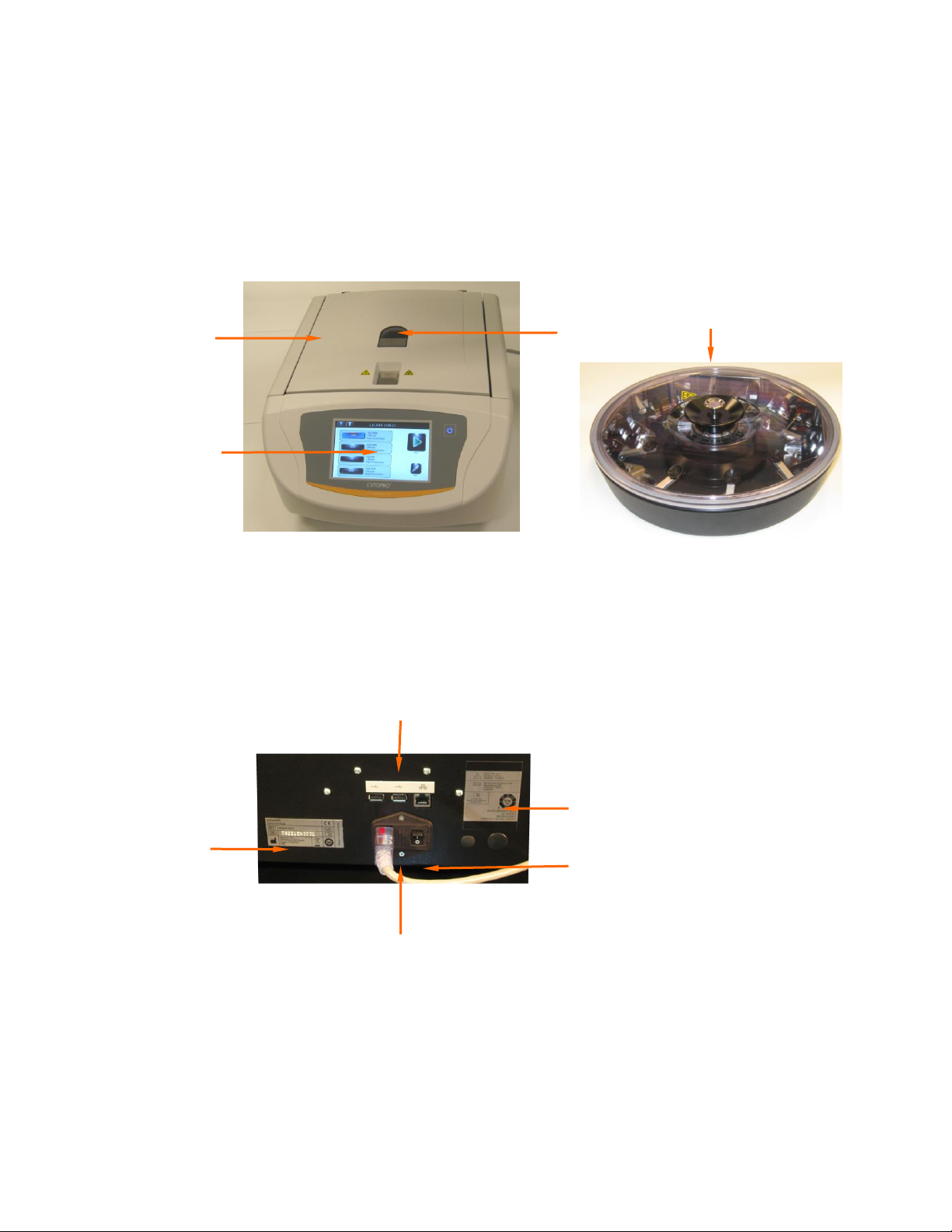
Figure 1: The Cytopro Cytocentrifuge
1–Interactive Touchscreen/Display
2–Lid
3–Rotor Rotation Observation Port
4 –Cytopro Rotor
Figure 2: Instrument Rear Panel
1–Model and Serial Number Label
2–USB and Ethernet Connections
3–Rear Panel Label
4–Power Switch
5 –Power Entry Module/Fuse Door
3
1
2
4
1
3
2
4
5
12
SECTION 1
INTRODUCTION
1.1 Cytopro Cytocentrifuge Overview
The Cytopro Rotor
The Cytopro rotor holds up to eight sample chamber assemblies, and microscope slides. The
rotor operates on the drive hub of the instrument. The self-sealing, autoclavable rotor is
easy to load in a biological safety cabinet. The lid seals airtight to contain biological hazards.
The low-profile rotor allows easy access during loading. While in the rotor, slide labels are
always visible for easy sample identification.
Sample Chamber Holder
Each sample chamber holder uses spring compression to maintain the seal between
chamber and slide. This helps control the rate of absorption in the standard
chambers.
Depress the release lever to load and unload chamber assemblies and slides. This
lever action cleanly retracts the chamber away from the slide; slides are easily
removed without smearing the cells.
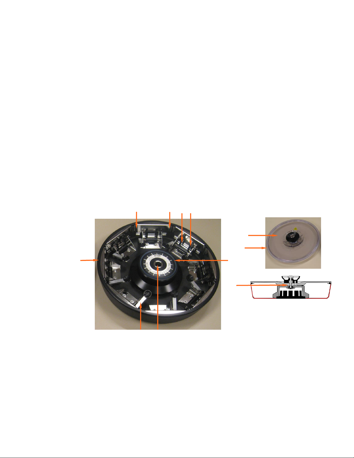
Figure 3: The Cytopro Rotor and Lid
1–Cytopro Cytocentrifuge Rotor
2–Slide Bracket (2 in each position)
3–Chamber Lever Fingers (2 in each position)
4 –Hub Seal
5–Locking Pin Receptacle
6–Chamber/Slide Release Lever
7–Rotor Lid with Locking Lid Latch
8–Bowl Seal
9–Cytopro Rotor with Locking Lid
2
1
8
5
6
7
3
2
4
9
8

13
SECTION 1
INTRODUCTION
1.1 Cytopro Cytocentrifuge Overview
Figure 4: Front Panel and Touchscreen
1–Standby/Ready Button
2–Touchscreen
The front panel features an interactive touchscreen display. Refer to Touchscreen and User
Interface (Section 1.2, Table 5) for more information.
Single Sample Chamber
The reusable single chamber features a dual-port sample loading port system that places a
38.5 mm2(7 mm diameter) spot on the microscope slide.
Tunnel Port
The tunnel port allows up to 200 µL of fluid to be placed directly into the chamber tunnel.
This allows flexibility in sample treatment, including in situ fixation and pad prewetting.
Sample Port
Load samples into the sample port for most applications. The sample well holds up to 0.5 mL
of fluid. Use a pipette to load sample fluid through the open ports or through air vents in the
chamber cap. See Section 3.1 for more information.
Chamber Pressure Ring
The raised ring at the end of the chamber tunnel seals the Cytopad against the glass slide to
restrict fluid flow during cytocentrifugation.
1
2

14
SECTION 1
INTRODUCTION
1.1 Cytopro Cytocentrifuge Overview
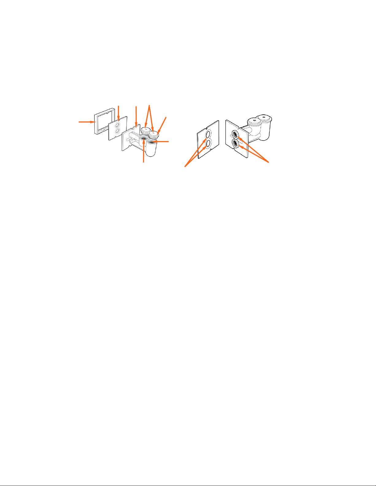
Figure 5: Single Chamber Assembly
1 –Chamber Frame
2 –Cytopad
3 –Chamber Base
4 –Tunnel Port Cap Vent
5 –Sample Well Cap Vent
6 –Cap
7–Sample Well
8 –Tunnel Port
9 –Chamber Tunnel
10 –Flow Control Ring
11 –Chamber Pressure Ring
Dual Sample Chambers
Dual chambers are designed to operate the same way as single chambers. The reusable dual
sample chambers allow you to place two 38.5 mm2(7 mm diameter each) spots of specimen on
the same microscope slide.
Dual Chamber Wells
Each sample well holds up to 0.3 mL of fluid (a total of 0.6 mL per slide). Use a
pipette to load sample fluid through the open ports or through air vents in the
chamber cap. See Section 3.1 for more information.
1
6
11
7
2
34 5
8
10
9
15
SECTION 1
INTRODUCTION
1.1 Cytopro Cytocentrifuge Overview
Figure 6: Dual Sample Chamber
1 –Chamber Frame
2 –Cytopad
3 –Chamber Base
4 –Cap Vents
5 –Cap
6 –Sample Wells
7 –Chamber Pressure Rings
8 –Flow Control Rings
Cytopro Magnum® Sample Chambers
The disposable, non-reusable Cytopro Magnum sample chamber allows you to place a
rectangular 315 mm2spot of specimen on a single microscope slide.
Sample Well
The sample well holds up to 6.0 mL of fluid. The sample can be either poured into
the sample well or pipetted through the open port in the sample well cap. Make
sure the chamber cap is properly secured prior to running the sample. Failure to do
so may allow fluid to leak into the rotor.
Chamber Sealing Gasket
The gasket at the end of the sedimentation chamber seals the Cytopro Magnum
against the glass slide to prevent fluid from leaking during cytocentrifugation.
Fluid Absorption Chambers
The two fluid absorption chambers are filled with an absorbent media that absorbs
the residual sample fluid after the cells are removed through cytocentrifugation.
NOTE: The absorbent media may turn yellow with age and light exposure. This color
change does not affect the absorption properties of the media and the chambers
can still be used with confidence.
1
8
6
2
3
4
5
6
7

16
SECTION 1
INTRODUCTION
1.1 Cytopro Cytocentrifuge Overview
Figure 7: Cytopro Magnum Chamber
1 –Cytopro Magnum Chamber
2 –Chamber Cap
3 –Suspension Fluid Absorption Chambers (2)
4 –Sealing Gasket
Cytopad® Absorption Pads
Cytopads (standard chambers only) absorb suspension fluid and allow sample cells to
sediment onto the microscope slide. Cytopads feature compressed flow-control rings for
controlled absorption of suspension fluids.
Cytopads are available in two absorption rates. The slow (tan) pad is for rapidly absorbed
fluids of low viscosity, low cellularity, or low turbidity. Use the fast (white) pad for more
viscous cell suspensions.
NOTE: Tan pads may vary in color from lot to lot and even from pad to pad. These color
differences do not change the performance of the pad. The tan color is used to differentiate
these pads from the white pads.
Cytopads are held securely between the chamber and the chamber frame for dependable
performance.
Figure 8: Cytopad Absorption Pads
1 –Flow Control Rings
2 –Indexing Notches
1
4
3
2
1
1
2
17
SECTION 1
INTRODUCTION
1.1 Cytopro Cytocentrifuge Overview
Chamber Frame
Chamber frames accept either single or dual replacement pads and have a cutaway to prevent
cells from being smeared as the chamber assembly is removed. Indexing pins on the frame
ensure correct Cytopad alignment. Cytopads come pre-attached to chambers or in boxes of 100
for attaching to reused chambers.
Figure 9: Chamber Frame
1 –Clearance Cutaway
2 –Indexing Pins
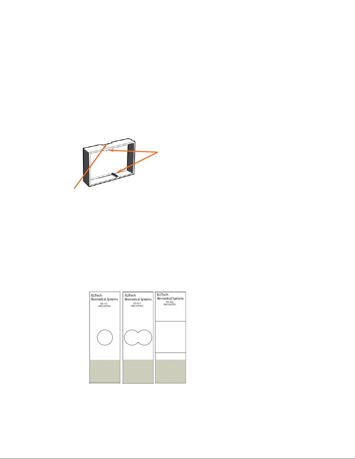
Microscope Slides
Use standard (25 x 75 mm) glass microscope slides. For cytology specimens, use coated
slides to reduce cell loss during wet fixation and staining.
Elitech Group offers specially designed target slides for the Cytopro system. These slides are
available in uncoated (single SS-117; dual SS-217; Cytopro Magnum SS-232) and Poly-L-
Lysine coated (single SS-118; dual SS-218; Cytopro Magnum SS-233).
Figure 10: Microscope Slides
1
2

18
SECTION 1
INTRODUCTION
1.1 Cytopro Cytocentrifuge Overview
Barcode Reader
An optional barcode reader is available for the Cytopro Cytocentrifuge.
Figure 11: Barcode Reader

19
SECTION 1
INTRODUCTION
1.2 Touchscreen and User Interface
Users control all instrument functions from the interactive touchscreen display.
Table 5: Front Panel/Main Screen Function Keys
Button
Name
Description
Standby/Ready
With instrument power ON:
Blue = Ready
Amber = Standby
Pressing Standby places instrument into
standby mode
The Standby/Ready button also accesses the
touchscreen calibration function. Refer to
System Setup Menu, (Section 2.1)
System Information
Shows the system information, including serial
number and software version. Allows access to
the System Setup features. Refer to System
Setup Menu, (Section 2.1).
Help
Opens the software Help file
Programs
Allows users to select or edit programs
Start/Load Slides
Begins a cycle. The Start button is inactive until
a program is created. Refer to Creating a
Cytocentrifuge Program (Section 2.1)
With Slide Tracking enabled, opens the Scan
and Load Slides and Specimen menu, (Section
2.1)
Table of contents
Other ELITechGroup Laboratory Equipment manuals


Popular Laboratory Equipment manuals by other brands


Belden
Belden HIRSCHMANN RPI-P1-4PoE installation manual

Koehler
Koehler K1223 Series Operation and instruction manual

Globe Scientific
Globe Scientific GCM-12 quick start guide

Getinge
Getinge 86 SERIES Technical manual

CORNING
CORNING Everon 6000 user manual

Biocomp
Biocomp GRADIENT MASTER 108 operating manual


