manuals.online logo
Brands
  1. Home
  2. •
  3. Brands
  4. •
  5. Eliwell
  6. •
  7. Controllers
  8. •
  9. Eliwell EWPC 961/S User manual

Eliwell EWPC 961/S User manual

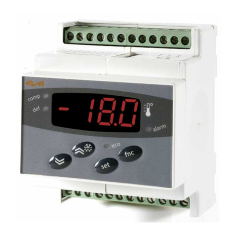
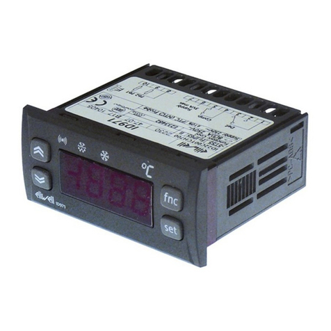
The EWPC 961/S is a temperature
controller specifically designed for
refrigeration applications.
The instrument is equipped with a
RS-485 port for the purpose of con-
necting it into a Televis system.
GENERAL DESCRIPTION
The EWPC 961/S is a temperature con-
troller specifically designed for refrigeration
applications and provides time control for
off-cycle defrost management. It incorpo-
rates an output relay for compressor con-
trol and a PTC sensor input. Furthermore,
the instrument is equipped with a RS-485
port for the purpose of connecting it into a
Televis system. A number of parameters are
displayed alphanumerically to set up the in-
strument for each specific application.
The EWPC 961/S is supplied in the popu-
lar “32x74” ELIWELL housing.
OPERATION
The EWPC 961/S is designed to operate
strictly as a cooling control, which means
that the switching differential is positive: the
compressor cuts off at setpoint and is
started at a temperature of set plus differ-
ential. The on-board microprocessor pro-
vides several timing functions for the
defrost; the defrost cycle as well the de-
frost cycle duration are user selectable.
At the start of each defrost cycle, the com-
pressor is simply stopped, regardless of
the temperature control circuit.
In addition, the EWPC 961/S offers several
system protection features, all easy to un-
derstand and easy to program This instru-
ment is compatible with Televis software rel
2.4 or greater. In case its use with different
software releases is required contact your
supplier or Eliwell Customers’ Service.
FRONT KEYPAD
SET: push and release to display the set-
point for 5 seconds. During this period the
“SET” status light is on and the setpoint
can be changed with the “UP” or “DOWN”
button only. The system will automatically
switch to normal display after 5 seconds
upon release of buttons and the new value
will be memorized.
UP: used to increase the setpoint value, as
well as the parameter when in program-
ming. When held down for a few seconds,
the change rate accelerates.
DOWN: same functions, except to de-
crease a value.
DEFROST: push to initiate a manual de-
frost cycle (override of programmed defrost
start; programmed time resets to zero).
Manual defrost can not be started while in
setpoint or in parameter programming
mode.
This button must be activated for 5 sec-
onds to start a defrost; the “DEF” status
light will come on and the compressor is
stopped.
Led “COMP”: status light of the internal
compressor relay. It is ON when the com-
pressor is ON.
Led “SET”: it is on during Setpoint display
and programming; it blinks during parame-
ter programming.
Led “DEF”: status light of the defrost. It is
on during automatic defrost; it blinks dur-
ing manual defrost.
PARAMETER PROGRAMMING
Programming is easily accessed by holding
the “SET” button down for more than
5 seconds; the first parameter is displayed
while the status light “SET” remains blink-
ing during the programming period.
Other parameters are accessed with the
“UP” and “DOWN” button. With the “SET”
button, the actual setting of each parame-
ter is displayed. To change a parameter
setting, push the “SET” plus the “UP” (or
“DOWN”). The system will automatically re-
turn to its normal operating mode a few
seconds after the programming procedure
is completed or interrupted.
DESCRIPTION OF PARAMETERS
diF: diFferential.
Switching differential (histeresis); it will al-
ways be set with positive value (make on
rise).
HOW IT IS MADE
• Dimensions: front 74x32 mm
(2.913x1.260"), depth 67 mm
(2.637")
• Mounting: flush panel mount with
mounting bracket
• Protection: the instrument front-
panel is waterproof IP65; an op-
tional snap-on cover can be
supplied to provide additional pro-
tection of the rear terminal block
• Connections: screw terminal block
(2.5 mm2; one wire each terminal
only, in compliance with VDE
norms)
• Display: 12.5 mm LED (0.50")
• Output: one (1) SPDT relay 8(3)A
250VA
• Input: PTC probe
• Serial connection: RS-485 serial
port for connection to the Televis
system
• Televis system compatibility: soft-
ware release 2.0.4 or greater
• Resolution: 1 °C (°F)
• Accuracy: better than 0.5% of full
scale
• Power supply: 12…24 VA/C
WHAT IT IS
EWPC 961/S
freezer control with Televis output
2EWPC 961/S 7/2000 ing
LSE: Lower SEt.
This is the lower limit below which the user
cannot change the setpoint.
HSE: Higher SEt.
Similar to “LSE”, however setting an upper
limit for the setpoint.
CAL: CALibration.
Temperature read-out offset to allow for a
fixed adjustment up or down due to probe
location, if desired.
cPP: compressor Probe Protection.
Select compressor relay status in case of
room probe defect.
oF = compressor OFF in case of probe de-
fect;
on = compressor ON in case of probe de-
fect.
ctP: compressor type Protection.
Select the type of (short-cycle) protection
best suited for the compressor; the actual
delay time is programmed with the next
parameter.
nP = no Protection;
don = delay on start: delay applies when
relay is energized;
doF = delay at switching oFf. Delay after
stop, i.e. time between stop and subse-
quent start;
dbi = delay between two successive starts.
Limits the number of start-ups per hour.
cdP: compressor delay Protection.
The time delay - in minutes - applicable to
the previous parameter “ctP”.
dct: defrost count type.
dF = digiFrost®: defrost starting time (“dit”)
is calculated based on accumulative com-
pressor running time;
rt = real time: defrost initiation frequency is
based on real time. Time between defrost
starts is always the same;
SC = Stop Compressor: a defrost cycle is
activated each time the compressor stops;
Fr = Free (the compressor relay has no re-
lation with the defrost functions and con-
tinues to regulate on Setpoint).
dit: defrost interval time.
Defrost initiation frequency in hours.
dEt: defrost Endurance time-out.
Defrost safety limit, expressed in minutes.
Defrost cycle is terminated, regardless
whether fully completed.
ddL: defrost display Lock.
Select whether or not to lock in the actual
box temperature display during a defrost.
n = no: during defrost the actual box tem-
perature is displayed;
y = yes: the temperature displayed at the
start of a defrost is locked in and does not
change during this cycle;
Lb = Label: during the defrost the label
“dEF” is displayed to indicate a defrost is in
progress.
NOTE: with the “y” and “Lb” selection, the
display remains locked until the box tem-
perature is pulled down again and reaches
setpoint value.
HAL: Higher ALarm.
LAL: Lower ALarm.
AFd: Alarm (Fan) differential.
PAO: Power-on Alarm Override.
dAo: defrost Alarm override.
dPo: defrost (at) Power on.
Selects whether the system should go
through a defrost cycle at start-up (or after
a power failure).
n = no;
y = yes.
doh: defrost offset.
Time delay of defrost start, expressed in
minutes.
dEA: dEvice Address.
To select the (address) label of the device in
relation to the supervisory system.
FAA: FAmily Address.
To select the (family) label of the device in
relation to the supervisory system; further
as “dEA”.
tAb: tAble of parameters.
This shows the configuration of the para-
meters as set in the factory; can not be
modified (for factory identification and di-
agnostic purposes only).
INSTALLATION
The instrument is designed for flush panel
mounting. Insert the unit through a
71x29 mm panel cut-out and affix with the
U-bracket supplied. The ambient tempera-
ture around the instrument should be kept
between –5 and 65 °C (23…149 °F).
CONNECTIONS
EWPC 961/S
6 7 8 9
POWER SUPPLY
510
1 2 3
+–
RS-485
compressor
thermostat
PTC probe
DEFAULT SETTINGS - STANDARD MODELS
Parameter
diF
LSE
HSE
CAL
cPP
ctP
cdP
dct
dit
dEt
ddL
HAL
LAL
AFd
PAO
dAo
dPo
doh
dEA
FAA
tAb
Description
diFferential
Lower SEt
Higher SEt
CALibration
compressor Probe Protection
compressor type Protection
compressor delay Protection
defrost count type
defrost interval time
defrost Endurance
defrost display Lock
Higher Alarm
Lower Alarm
Alarm (Fan) differential
Power-on Alarm Override
defrost Alarm override
defrost (at) Power on
defrost offset
dEvice Address
FAmily Address
tAble of parameters
Range
1…15
–99…HSE
LSE…99
–20…20
oF / on
nP / don / doF / dbi
0…15
dF / rt / SC
0…31
1…99
n / y / Lb
1…50
1…50
1…50
0…10
0…10
n / y
0…59
0…14
0…14
/
Unit
°C / °F
°C / °F
°C / °F
°C / °F
flag
flag
minutes
flag
hours
minutes
flag
°C / °F
°C / °F
°C / °F
hours
hours
flag
minutes
number
number
/
Default
2
–55
40
0
oF
nP
0
rt
6
30
y
50
50
1
10
10
n
0
0
0
/
3EWPC 961/S 7/2000 ing
Select a location which will not be subject
to high humidity or condensation and allow
some ventilation to provide cooling to the
instrument.
ELECTRICAL WIRING
The instrument is equipped with an internal
screw terminal block suitable for max
2.5 mm2wiring (one wire each terminal
only, in compliance with VDE norms).
Make sure that the power supply corre-
sponds with the rating shown on the in-
strument, i.e. 12…24 Va/c.
The 2-wire PTC type probe does not re-
quire polarity and can easily be extended
by using common 2-lead wire.
It is strongly recommended to run the
probe cable separate from line voltage
wiring. Also, it is good practice to install the
tip of the probe in upright position, to avoid
moist from entering into the stainless steel
sensor housing. The output relay contacts
are voltage-free and are suitable for in-line
switching of compressors up to 0.5 HP at
220 Va(or 0.25 HP to 110 Va). For larger
loads, an external contactor must be used.
ERROR ANNOUNCIATION
The instrument is provided with only one
error message “E1”, both in case of short-
ed sensor and in case of sensor break, or
sensor absence.
The “E1” error message also appears in
the event of underrange of the system tem-
perature or in the event of overrange of the
system temperature.
TECHNICAL DATA
Housing: black ABS plastic, self-estin-
guishing.
Dimensions: front 74x32 mm
(2.913x1.260"), depth 67 mm (2.637").
Mounting: flush panel mount with mount-
ing bracket.
Protection: the instrument frontpanel is
waterproof IP65; an optional snap-on cov-
er can be supplied to provide additional
protection of the rear terminal block.
Connections: screw terminal block
(2.5 mm2; one wire each terminal only, in
compliance with VDE norms).
Display: 12.5 mm LED (0.50").
Push buttons: located on front panel.
Data storage: non-volatile EEPROM
memory.
Operating temperature: –5…65 °C
(23…149 °F).
Storage temperature: –30…75 °C
(–22…167 °F).
Output: one (1) SPDT relay 8(3)A 250Va.
Input: PTC probe.
Serial connection: RS-485 serial port for
connection to the Televis system.
Televis system compatibility: software
rel 2.0.4 or greater.
Resolution: 1 °C (°F).
Accuracy: better than 0.5% of full scale.
Power supply: 12…24 Va/c.
DISCLAIMER
This manual and its contents remain the
sole property of Invensys Climate Controls
s.p.a., and shall not be reproduced or dis-
tributed without authorization. Although
great care has been exercised in the

preparation of this document, Invensys
Climate Controls s.p.a., its employees or
its vendors, cannot accept any liability
whatsoever connected with its use.
Invensys Climate Controls s.p.a. reserves
the right to make any changes or improve-
ments without prior notice.
Invensys Climate Controls s.p.a.
via dell'Industria, 15
Zona Industriale Paludi
32010 Pieve d'Alpago (BL)
ITALY
Telephone +39 0437 986111
Facsimile +39 0437 986066
Email [email protected]
Internet http:/www.climate-eu.invensys.com
7/2000 ing
cod. 9FT40072

Other Eliwell Controllers manuals

Eliwell ID 961 User manual

Eliwell

Eliwell ID 961 User manual

Eliwell ID 974 User manual

Eliwell

Eliwell ID 974 User manual

Eliwell IDplus 961 User manual

Eliwell

Eliwell IDplus 961 User manual

Eliwell EWKPlus 978 User manual

Eliwell

Eliwell EWKPlus 978 User manual

Eliwell EW961 User manual

Eliwell

Eliwell EW961 User manual

Eliwell RGF 312 User manual

Eliwell

Eliwell RGF 312 User manual

Eliwell EWDR 983/CS User manual

Eliwell

Eliwell EWDR 983/CS User manual

Eliwell ID 983LX HACCP User manual

Eliwell

Eliwell ID 983LX HACCP User manual

Eliwell EWHT 1800LX User manual

Eliwell

Eliwell EWHT 1800LX User manual

Eliwell EWRC 300 NT Series User manual

Eliwell

Eliwell EWRC 300 NT Series User manual

Eliwell EWRC 300 NT Series User manual

Eliwell

Eliwell EWRC 300 NT Series User manual

Eliwell IC 915 NTC/PTC User manual

Eliwell

Eliwell IC 915 NTC/PTC User manual

Eliwell IWP 760 LX User manual

Eliwell

Eliwell IWP 760 LX User manual

Eliwell ICPlus 915 User manual

Eliwell

Eliwell ICPlus 915 User manual

Eliwell EWDB 111 User manual

Eliwell

Eliwell EWDB 111 User manual

Eliwell ID 985 User manual

Eliwell

Eliwell ID 985 User manual

Eliwell EW 4800 User manual

Eliwell

Eliwell EW 4800 User manual

Eliwell IC 912 Pt100-TC User manual

Eliwell

Eliwell IC 912 Pt100-TC User manual

Eliwell ID 400 User manual

Eliwell

Eliwell ID 400 User manual

Eliwell ID 970 User manual

Eliwell

Eliwell ID 970 User manual

Eliwell 210 L Series User manual

Eliwell

Eliwell 210 L Series User manual

Eliwell ID 985 E User manual

Eliwell

Eliwell ID 985 E User manual

Eliwell IC 912 User manual

Eliwell

Eliwell IC 912 User manual

Eliwell ID 971 User manual

Eliwell

Eliwell ID 971 User manual

Popular Controllers manuals by other brands

Avonic AV-CON100 user manual

Avonic

Avonic AV-CON100 user manual

Siemens SIMATIC PCS 7 CPU 410-5H System manual

Siemens

Siemens SIMATIC PCS 7 CPU 410-5H System manual

AMCOL 6000-ETC Operator's manual

AMCOL

AMCOL 6000-ETC Operator's manual

ZIEHL-ABEGG Acontrol PKE-6 operating instructions

ZIEHL-ABEGG

ZIEHL-ABEGG Acontrol PKE-6 operating instructions

Tunze Osmolator 3 Instructions for use

Tunze

Tunze Osmolator 3 Instructions for use

DEXAPLAN SL 614 -  2 DU 5-2008 manual

DEXAPLAN

DEXAPLAN SL 614 - 2 DU 5-2008 manual

TECH ST-402N PWM user manual

TECH

TECH ST-402N PWM user manual

Martin M6 Series manual

Martin

Martin M6 Series manual

Siemens Simatic S7-1500 System manual

Siemens

Siemens Simatic S7-1500 System manual

Codan MT-3 Technical note

Codan

Codan MT-3 Technical note

Johnson Controls M9310-HGA-3 installation guide

Johnson Controls

Johnson Controls M9310-HGA-3 installation guide

HIRED-HAND EVOLUTION BIRD SCALE owner's manual

HIRED-HAND

HIRED-HAND EVOLUTION BIRD SCALE owner's manual

Jung FMST50UP operating instructions

Jung

Jung FMST50UP operating instructions

Unipower X75 Series Installation & operating manual

Unipower

Unipower X75 Series Installation & operating manual

Newport XPS Programmer's manual

Newport

Newport XPS Programmer's manual

ABB ACH550-01 user manual

ABB

ABB ACH550-01 user manual

Regin EXOcompact C80 manual

Regin

Regin EXOcompact C80 manual

Linak ACTUATOR LA36 Connection diagram

Linak

Linak ACTUATOR LA36 Connection diagram

manuals.online logo
manuals.online logoBrands
  • About & Mission
  • Contact us
  • Privacy Policy
  • Terms and Conditions

Copyright 2025 Manuals.Online. All Rights Reserved.