manuals.online logo
Brands
  1. Home
  2. •
  3. Brands
  4. •
  5. Elkay
  6. •
  7. Chiller
  8. •
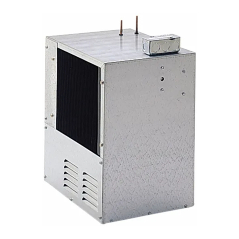
  9. Elkay ERS12Y Installation manual

Elkay ERS12Y Installation manual

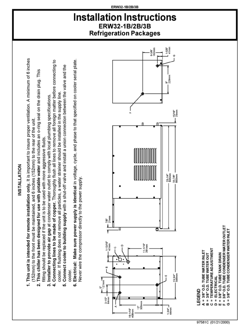
ERS1*2F
Page 1 97718C (Rev. E - 09/15)
230V Refrigeration Package
7"
179mm
6 1/4"
160mm
2 3/8"
61mm
1 1/8"
28mm
2 3/8"
61mm
10"
253mm
17 1/8"
434mm
2"
51mm
14"
354mm
E
D
C
A
B
3 1/2"
89mm
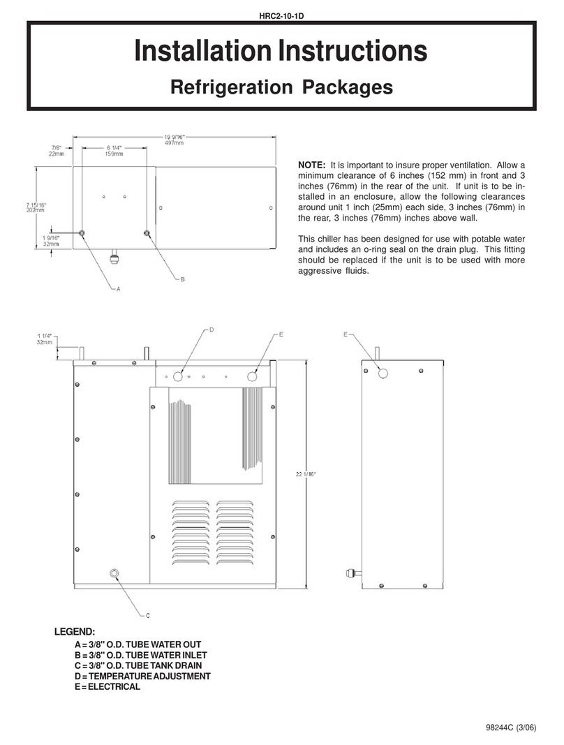
Connections
A = 1/4" (64mm)O.D. Tube. Water Outlet
B = 1/4" (64mm)O.D. Tube. Water Inlet
C = Temperature Adjustment
D = Electrical
E = 1/4" (64mm)O.D. Tube. Tank Drain
Installation / Care / Use Manual
Model: ERS12Y
Description
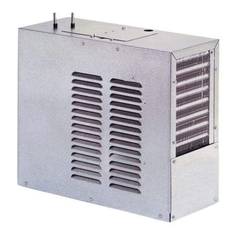
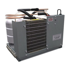
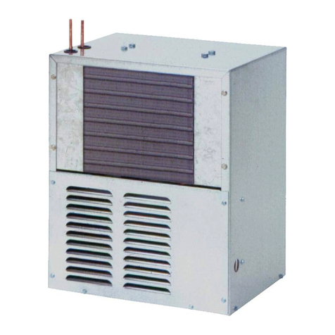
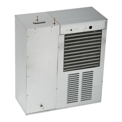
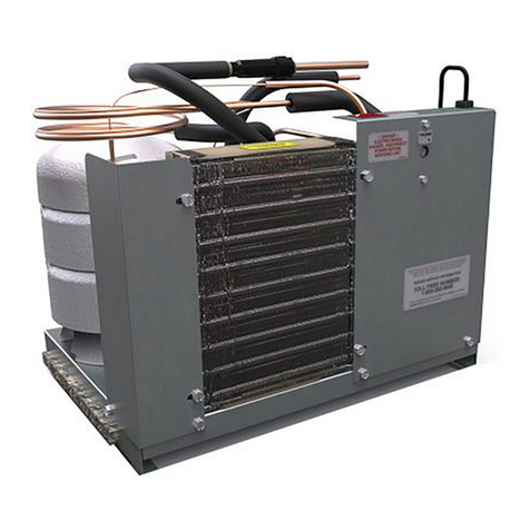
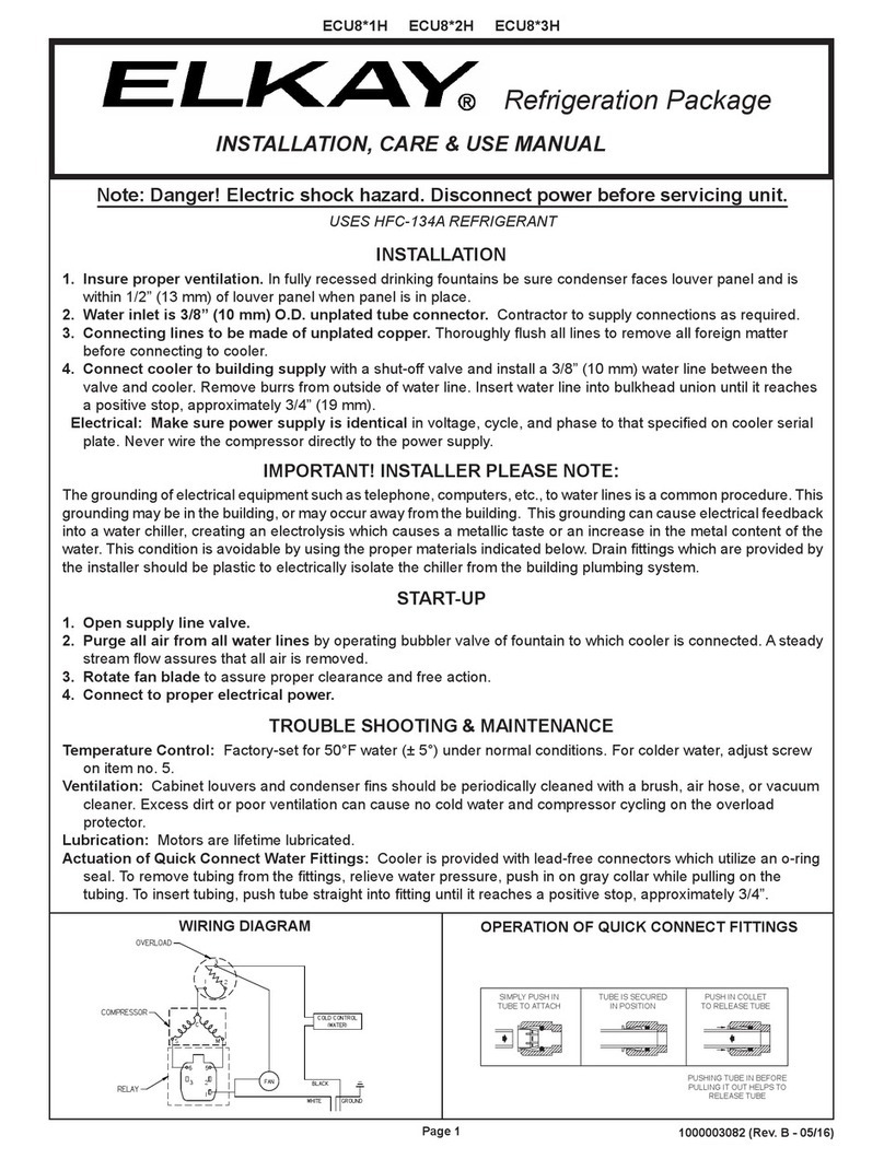
Remote Water Chillers are designed to reduce the temperature of potable water that is routed through the water chiller.Remote Water Chillers
are designed to be installed in properly ventilated, non-visible locations .
Ratings
• Electrical: 230Vac, 50Hz, ___A (see nameplate), 1 phase.
• Ambient Air Temperature: 10-38 °C (50-100.4 °F).
• Water Pressure: 20-100 psig (0.14-0.69 MPa).
• Maximum Water Temperature: 90 °F (32 °C).
• Refrigerant: HFC-R134a
• Ingress Protection: IP2x
• For Indoor Commercial Use only.
DANGER – Indicates death or serious injury will result if proper precautions are not taken.
WARNING – Indicates death, serious injury or property damage can result if proper precautions are not taken.
CAUTION – Indicates some injury or property damage may result if proper precautions are not taken.
Authorized Service Personnel – Factory trained personnel or personnel having working knowledge of electrical, plumbing and
machine (appliance) maintenance procedures.
Safety
DANGER
• Please read these instructions completely before starting the installation or performing any service. Failure to follow the instructions
and safety precautions in this manual can result in serious injury or death.
• After installation, keep these instructions in a safe location for future reference.
• Electric supply must be identical in voltage, cycle, and phase to that specied on nameplate.
• A means for disconnecting electrical supply to the unit must be incorporated in the xed wiring in accordance with wiring rules. This is to
allow electrical disconnection of the unit from electrical supply after installation.
WARNING
• For use with clean, clear potable drinking water only. Do not use with water that is microbiologically unsafe or of unknown quality
without adequate disinfection before the system.
• Installation and connection to water and electrical mains must be in compliance with local and national laws.
• All Installation and Service work must be performed by an authorized service personnel.
CAUTION
• This appliance can be used by children aged from 8 years and above and persons with reduced physical, sensory, or mental
capabilities or lack of experience and knowledge if they have been given supervision or instructions concerning use of the appliance in
a safe way and understand the hazards involved. Children shall not play with the appliance. Cleaning and user maintenance shall not
be made by children without supervision.
Denitions
Original Instructions
PAGE 2
97718C (Rev. E - 09/15)
ERS1*2F
Installation
For correct and safe installation, please read these instructions completely.
DANGER
• All Installation work must be performed by an authorized service personnel.
• Disconnect electrical supply serving the Installation area to reduce risk of electrocution.
• Unit not suitable for installations where water jets could be used.
WARNING
• Shut off water supply serving the Installation area to reduce risk of water damage.
• Installation area must have minimum required clearances and ventilation for safe operation.
• Never wire compressor directly to electrical supply.
CAUTION
• Hose-sets are not to be used for connecting to water mains.
• Tools/Items required but not provided.
o Safety Glasses
o Protective Gloves
o Hex drives.
o Water Shut-off Valve with 3/8" (9.5mm) compression outlet.
o Fasteners for wall type.
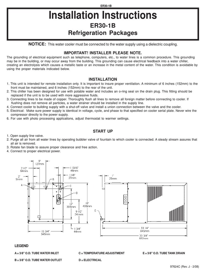
This unit can be installed underneath a commercial or industrial sink, in
a cabinet not less than 36" (914mm) wide (inside dimension). Two air
openings with a minimum of 40" square (1016mm/square) each, minimum
of 75% open area, must be provided in the cabinet. One opening must
be in the overhang of the toe space, the other opening near the top of the
cabinet. The remote unit must be installed with a minimum of 3"(76mm)
clearance between the unit and the rear wall of the cabinet. It can be in-
stalled ush against either side wall of the cabinet. The side louvers which
are not against the cabinet must not be blocked by objects located within
4" (102mm) of the louvers. In addition, a minimum of 1 to 2" (25 to 51mm)
clearance must be provided between the toe space air opening and front
of the unit.
Water inlet and outlet are 1/4" (6 mm) O.D. tubes with connectors sup-
plied.
Connecting lines to be of copper, thoroughly ushed to remove all foreign
matter before being connected to cooler.
Connect cooler to building water mains with a shut-off valve and install
a 3/8" O.D. (10mm) unplated copper tube between the valve and cooler.
Remove burr from outside of water line. Insert water line into tting until it
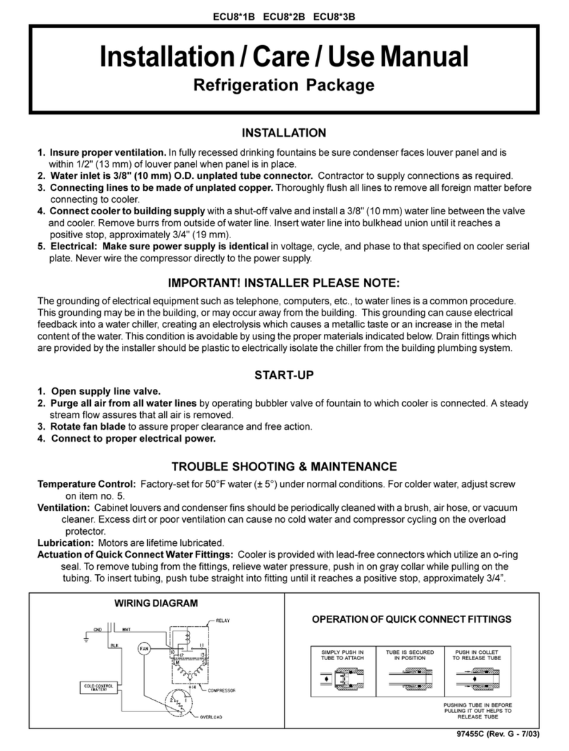
reaches a positive stop, approximately 3/4" (19mm).
Installation Steps
1.
2.
3.
4.
Wiring Instructions
1. Turn off electrical supply to chiller circuit
2. Remove top cover to gain access to electrical box
3. Join electrical wire to unit using 3/8” cable clamp
connector or appropriate conduit connector
4. Connect ground wire to ground screw (provided)
5. Connect black wire to 230VAC
6. Connect white wire to Neutral line
7. Replace top cover and turn on electrical supply.
Start-Up
1. Open water shut-off valve.
2. Purge air from all water lines by operating bubbler valve
of fountain to which cooler is connected. Steady water
stream assures all air is removed.
3. Rotate fan to insure proper clearance and free fan action.
4. Connect to electrical supply.
A) Air Vent
B) Condenser Side
Forward
C) Can be mounted
ush against either
side of cabinet
Water Mains Connection
A) 1/4” (6mm) O.D. Tube. Water Inlet to Chiller
B) Building Water Mains
C) Water Shut-Off Valve (not provided)
B
A
DB
A
8 C
S
41
2R
E
F
G
C
B
A
230Vac, 50Hz Wiring Diagram
A) White = Neutral
B) Black = 230Vac
C) Ground Screw = Earth
D) Fan
E) Temperature Control
F) Internal Overload Protector
G) PTC Starter
A B
C
ERS1*2F
Page 3 97718C (Rev. E - 09/15)
Service
For proper and safe servicing, please read these instructions completely.
DANGER
• All Service and Maintenance must be performed by an authorized service personnel.
• Disconnect electrical supply to the unit before any service work to reduce risk of electrocution.
• Shut off water supply serving the unit before any service work to reduce risk of water damage.
CAUTION
• Tools/Items required but not provided, for Servicing:
o Safety Glasses
o Protective Gloves
o Hex drives.
Service: Adjustments
1. Temperature Control: Water temperature is factory set at 50ºF ± 5º (10ºC ± 5º) under normal conditions. For colder water, adjust screw on
item no. 10 in clockwise direction.
Service: Inspection/Cleaning
• Inspect Water Chiller twice each year for proper operation and performance.
• Inspection of the unit will require disconnecting electrical supply, removal of panels, etc. and reassembly and return to service practices.
2. Condenser Fan Motor: Conrm condenser fan turns freely. If the condenser fan does not spin freely, have an authorized service personnel
replace.
3. Ventilation: Cabinet louvers and condenser ns should be periodically cleaned with a brush, air hose or vacuum cleaner. Cleaning should be
done twice each year or more frequently if needed due to environment. Excess dirt or poor ventilation can cause no cold water and
compressor cycling on the compressor overload protector.
4. Water Flow: Conrm proper water ow. If water ow is slow, inspect lter or inline strainer for restriction. Replace lter cartridge if required.
Disassemble inline strainer and clean if required.
5. Lubrication: Motors are lifetime lubricated.
Replacement Parts: Parts List
*INCLUDES RELAY & OVERLOAD. IF UNDER WARRANTY, REPLACE
WITH SAME COMPRESSOR USED IN ORIGINAL ASSEMBLY.
NOTE: All correspondence pertaining to any of the above water cool-
ers or orders for repair parts MUST include Model No. and Serial No. of
cooler, name and part number of replacement part.
For Replacement Parts, contact your local distributor or call 1.800.834.4816
Elkay Manufacturing Co. 2222 Camden Court - Oak Brook, IL 60523 U.S.A - 630.574.8484
7, 14, 20
6, 9, 11
21
15
17
16
5
1, 8, 12, 13 10 3
4
19
2
18
ITEM NO. PART NO. DESCRIPTION
1 22000C BRACKET - FAN MOTOR
2 23084C PANEL - FRONT
3 23085C ELECTRICAL COVER
4 23086C PANEL-RIGHT SIDE & BACK
5 23087C LEFT SIDE
6 35768C COVER - RELAY
7 19037000 CLIP
8 30824C BLADE - FAN
9 36171C OVERLOAD
10 31513C COLD CONTROL
11* 35967C COMPRESSOR SERVICE PACK
12 31395C MOTOR - FAN
13 111543043890 NUT #6 HEX (FAN MOTOR MTG)
14 100806740570 GROMMET
15 66199C DRIER
16 61521C CONDENSER
17 66606C HEAT EXCHANGER
18 62031C DRAIN PLUG
19 66363C EVAPORATOR TANK ASSY
20 101516143550 STUD - COMPRESSOR MOUNTING
21 36166C RELAY

Other Elkay Chiller manuals

Elkay ER5 Series Instructions for use

Elkay

Elkay ER5 Series Instructions for use

Elkay ECH8 Installation manual

Elkay

Elkay ECH8 Installation manual

Elkay ERW32 User manual

Elkay

Elkay ERW32 User manual

Elkay ERW20-1C User manual

Elkay

Elkay ERW20-1C User manual

Elkay HRC4-19-1C User manual

Elkay

Elkay HRC4-19-1C User manual

Elkay ERW32-1B User manual

Elkay

Elkay ERW32-1B User manual

Elkay ECP8*1H Series Installation manual

Elkay

Elkay ECP8*1H Series Installation manual

Elkay ERS1-1D Installation manual

Elkay

Elkay ERS1-1D Installation manual

Elkay HRC2-10-1D User manual

Elkay

Elkay HRC2-10-1D User manual

Elkay ECH8 Installation manual

Elkay

Elkay ECH8 Installation manual

Elkay ER2 Installation manual

Elkay

Elkay ER2 Installation manual

Elkay HRC2-1C User manual

Elkay

Elkay HRC2-1C User manual

Elkay ERS1 1E Series Installation manual

Elkay

Elkay ERS1 1E Series Installation manual

Elkay HRC30-1B User manual

Elkay

Elkay HRC30-1B User manual

Elkay ER30-1B User manual

Elkay

Elkay ER30-1B User manual

Elkay ERW32-1C User manual

Elkay

Elkay ERW32-1C User manual

Elkay ER2-1D User manual

Elkay

Elkay ER2-1D User manual

Elkay ECP8 2GQ Series Installation manual

Elkay

Elkay ECP8 2GQ Series Installation manual

Elkay ECH8*2H Installation manual

Elkay

Elkay ECH8*2H Installation manual

Elkay EDF14C Installation manual

Elkay

Elkay EDF14C Installation manual

Elkay ERS1 2E Series Installation manual

Elkay

Elkay ERS1 2E Series Installation manual

Elkay ECU8*1H Series Installation manual

Elkay

Elkay ECU8*1H Series Installation manual

Elkay ERS1-1E/2E Installation manual

Elkay

Elkay ERS1-1E/2E Installation manual

Elkay ER194H Installation manual

Elkay

Elkay ER194H Installation manual

Popular Chiller manuals by other brands

Daikin SERHQ020BAW1 Installation and operation manual

Daikin

Daikin SERHQ020BAW1 Installation and operation manual

KKT KSC Series Operating	 instruction

KKT

KKT KSC Series Operating instruction

Advantage MGD-15W-MGD-ADV-02 instruction manual

Advantage

Advantage MGD-15W-MGD-ADV-02 instruction manual

SMC Networks HRS100-A?-20-? Operation manual

SMC Networks

SMC Networks HRS100-A?-20-? Operation manual

Carrier 30GT080-420 Installation, Start-Up and Service Instructions

Carrier

Carrier 30GT080-420 Installation, Start-Up and Service Instructions

Carrier AquaEdge 19DV series Controls operation and troubleshooting

Carrier

Carrier AquaEdge 19DV series Controls operation and troubleshooting

TECO TK Series Guideline

TECO

TECO TK Series Guideline

Carrier AquaEdge 23XRV Start-up, operation and maintenance instructions

Carrier

Carrier AquaEdge 23XRV Start-up, operation and maintenance instructions

American Panel AP20BCF200-3-XL Installation & operator's manual

American Panel

American Panel AP20BCF200-3-XL Installation & operator's manual

York R-407C Optimized manual

York

York R-407C Optimized manual

Daikin EWWD320 Installation, operation and maintenance manual

Daikin

Daikin EWWD320 Installation, operation and maintenance manual

Lennox MWC 180 Application guide

Lennox

Lennox MWC 180 Application guide

York YCAS0130 user manual

York

York YCAS0130 user manual

Galletti PERFORMA MPE Series Technical manual

Galletti

Galletti PERFORMA MPE Series Technical manual

SABROE ChillPAC operating manual

SABROE

SABROE ChillPAC operating manual

Johnson Controls York YCAL0014E Series Installation, operation & maintenance instructions

Johnson Controls

Johnson Controls York YCAL0014E Series Installation, operation & maintenance instructions

Morgan MCS-339 user manual

Morgan

Morgan MCS-339 user manual

York 53221 operating instructions

York

York 53221 operating instructions

manuals.online logo
manuals.online logoBrands
  • About & Mission
  • Contact us
  • Privacy Policy
  • Terms and Conditions

Copyright 2025 Manuals.Online. All Rights Reserved.