manuals.online logo
Brands
  1. Home
  2. •
  3. Brands
  4. •
  5. Elkay
  6. •
  7. Water Dispenser
  8. •
  9. Elkay EFHA8 1M Series Installation manual

Elkay EFHA8 1M Series Installation manual

PAGE 1 98973C (Rev. C - 04/16)
EFHA8*1M
INSTALLATION, CARE & USE MANUAL
Manual de Instalación, Cuidado y Utilización
Manuel d’installation/entretien/utilisation
EFHA Refroidisseurs d'eau Deluxe froids et chauds
EFHA Enfriadores de agua Deluxe servicio frío y caliente
EFHA Hot and Cold Service Deluxe Water Coolers
PAGE 2
98973C (Rev. C - 04/16)
EFHA8*1M
Uses HFC-134A refrigerant
Usa refrigerante HFC-134A
Utilise du uide frigorigéne HFC-134A
Note: Danger! Electric shock hazard. Disconnect power before servicing unit.
Nota: peligro! Peligro de descarga eléctrica. Desconecte antes de reparar la unidad.
Remarque : Danger ! Risque d'électrocution. Débrancher avant de réparer l'appareil.
FIG. 1
7
19
14 26
3 & 25
10
16
20
13
6
8 (SEE FIG. 5
VEA LA FIG. 5
VOIR FIG. 5
SEE FIG. 4
VEA LA FIG. 4
VOIR FIG. 4
30 (SEE FIG. 6
VEA LA FIG. 6
VOIR FIG. 6
21
17
24
12
22
5
15
4
23
9
PAGE 3 98973C (Rev. C - 04/16)
EFHA8*1M
18"
457mm
23"
584mm
2 1/2"
64mm
5"
127mm
40"
1016mm
41 1/2"
1054mm
4 5/8"
118mm
14 1/2"
368mm
C
A
B
D
E
EG
F
FIG. 2
FINISHED FLOOR
PISO ACABADO
PLANCHER FINI
EMPLACEMENT DE LA PRISE DE COURANT
E = INSURE PROPER VENTILATION BY MAINTAINING 4" (102mm) (MIN.) CLEARANCE FROM CABINET LOUVERS TO
WALL.
ASEGURE UNA VENTILACIÓN ADECUADA MANTENIENDO UN ESPACIO E 4" (102mm) (MÍN.) DE HOLGURA ENTRE
LA REJILLA DE VENTILACIÓN DEL MUEBLE Y LA PARED
ASSUREZ-VOUS UNE BONNE VENTILATION EN GARDANT 4" (102mm) (MIN.) ENTRE LES ÉVENTS DE L’ENCEINTE
ET LE MUR.
F = POWER CORD 4 FEET (1219mm) LONG
CABLE ELÉCTRICO DE 4 PIE (1219mm), DE LARGO
CORDON D’ALIMENTATION 4' (1219mm)
G = PLUMBING ROUGH-IN CAN BE LOCATED ANYWHERE WITHIN THIS AREA.
SE PUEDE COLOCAR EL DESBASTE DE LA TUBERÍA EN CUALQUIER LUGAR DENTRO DE ESTA ÁREA.
ON PEUT PLACER LA TUYAUTERIE DANS CETTE RÉGION.
LEGEND/LEYENDA/LÉGENDE
A = RECOMMENDED WATER SUPPLY LOCATION 3/8 O.D. UNPLATED COPPER TUBE CONNECT STUB 1-1/2 IN. (38mm) OUT
FROM WALL SHUT OFF BY OTHERS
SE RECOMIENDA UBICAR EL TUBO CORTO DE CONEXIÓN AL TUBO DE COBRE SIN CHAPAR DE 3/8" DE DIÁM. EXT. A 1-1/2"
(38mm) FUERA DE LA LLAVE DE PASO EN LA PARED COLOCADA POR TERCEROS.
EMPLACEMENT RECOMMANDÉ D'ALIMENTATION EN EAU PAR TUBE EN CUIVRE NON PLAQUÉ DE 3/8 PO. (9,5 mm) D.E.
CONNECTANT UNE TUYAUTERIE DE 1-1/2 PO. (38mm) DEPUIS LE ROBINET D'ARRÊT FOURNI PAR D'AUTRES.
B = RECOMMENDED LOCATION FOR WASTE OUTLET 1-1/4” O.D. DRAIN
UBICACIÓN RECOMENDADA PARA EL DRENAJE DE SALIDA DE AGUA, DE 1¼” DE DIÁMETRO.
EMPLACEMENT RECOMMANDÉ POUR LE DRAIN DE D.E. 1-1/4" DE SORTIE D’EAU.
C = 1-1/4 TRAP NOT FURNISHED**
PURGADOR DE 1¼ NO PROPORCIONADO**
SIPHON 1-1/4 NON FOURNI**
D = ELECTRICAL OUTLET LOCATION
UBICACIÓN DE LA TOMA DE ELECTRICIDAD
EMPLACEMENT DE LA PRISE DE COURANT
PAGE 4
98973C (Rev. C - 04/16)
EFHA8*1M
NOTE:
WHEN INSTALLING REPLACEMENT BUBBLER AND PEDESTAL, TIGHTEN
LOCKNUT ONLY TO HOLD PARTS SNUG IN POSITION.
DO NOT OVER TIGHTEN.
LOCKNUT
FIG. 4 FIG. 5
BASIN
ESTANQUE
BASSIN
NOTE:
LORSQUE VOUS INSTALLEZ UN NOUVEAU BARBOTEUR ET SOCLE,
RESSERREZ L’ÉCROU (ARTICLE 12) SEULEMENT SUFFISAMMENT POUR
GARDER LES PIÈCES BIEN EN PLACE.
NE PAS TROP SERRER.
NOTA:
CUANDO SE INSTALE EL BORBOTEADOR DE REPUESTO Y EL PEDESTAL,
APRIETE LA TUERCA (ARTICULO 12) SOLAMENTE PARA SOSTENER LAS
PIEZAS EN SU POSICIÓN.
NO APRIETE EMASIADO.
LEFT PANEL
PANEL IZQUIERDO
PANNEAU GAUCHE
20654C
21450C
27148C
FRONT PANEL
PANEL FRONTAL
PANNEAU AVANT
RIGHT PANEL (w/ hole)
PANEL DERECHO (sin aguero)
PANNEAU DROIT (sans trou)
COLOR TABLE
PANEL COLOR
TABLA DE LOS COLORES
COLOR DEL PANEL
TABLE DE COULEURS
COULEUR DU PANNEAU
Acier inoxydable
Santal
Gris granite
Acero inoxidable
Maderade sándalo
Granito grisáceo
27652C
27656C
27657C
20624C
21458C
27166C
20625C
21459C
N/A
RIGHT PANEL (w/o hole)
PANEL DERECHO (con aguero)
PANNEAU DROIT (avec trou)
FIG. 6
FIG. 7
11
18
Glass ller Shown for Reference Only.
Llenador de cristal demostrado para
la referencia solamente
Remplisseur de verre montré pour la
référence seulement
PART OF
ITEM 21
18
8
Stainless Steel
Sandalwood
Light Gray Granite
BASIN
ESTANQUE
BASSIN
1
COVER NUT
TAPA TUERCA
LA COUVERTURE DE
L'ÉCROU
BUTTON
BOTÓN
BOUTON
2
Stream height is factory set at 35 PSI. If supply pressure varies greatly from this, remove
items Cover Nut & Button and adjust screw on regulator. Clockwise adjustment will raise
stream and counter-clockwise adjustment will lower stream. For best adjustment, stream
should hit basin approximately 6-1/2" (165mm) from bubbler.
Le niveau d’écoulement est réglé en usine à 35 PSI. Si la pression varie beaucoup de
cela, supprimer des éléments couvrent écrou & bouton et ajustez la vis sur le régulateur.
Si vous ajustez dans le sens des aiguilles d’une montre, le jet augmentera et dans le
sens contraire, le jet diminuera. Le meilleur ajustement est lorsque le jet frappe le bassin
à environ 6-1/2" (165mm) du barboteur.
La altura del chorro se determina en la fábrica a 35 PSI. Si la presión del suministro varía
demasiado de este, retire las prendas cubierta tuerca & botón y ajuste el tornillo regulador.
El ajuste en el sentido de las agujas del reloj elevará el chorro y contra el sentido de las
agujas del reloj lo bajará. Para un mejor ajuste, el chorro deberá pegar en el estanque a
una distancia de aproximadamente 6½” (165mm) del borboteador.
PAGE 5 98973C (Rev. C - 04/16)
EFHA8*1M
ELKAY MANUFACTURING COMPANY • 2222 CAMDEN COURT • OAK BROOK, IL 60523 • 630.574.8484
ITEM NO. PART NO. DESCRIPTION
1
2
3
4
5
6
7
8
*9
10
11
12
13
14
15
16
17
18
19
20
21
22
23
24
25
26
N/S
Kit - pulsador y regulador/titular/tuercas
Filtro bifurcado
Tubo de escape
Soporte - Abrazadera
tercambiador / secador
Kit - reemplazo de evaporador
Estanque
Lavabo con el agujero de cristal del llenador
Ensamblado del borboteador
Paquete de servicio del compresor
Kit - relé/sobrecarga/protección eléctrica
Boquilla-Borboteador
Soporte de montaje caliente del tanque
Kit - tornillos de Control de fríos
Cable eléctrico
Kit - secador de condensador
Kit - ventilador Motor/cubierta/hoja/tuerca
El Tubo asta (el Corte a la longitud)
Kit - junta (Pack 25)(Glass Filler)
Fijador del abanico
Secador
Kit - Ensamblaje del tanque caliente
El Caber - El Broche de presión Del 1/4" Conecta
Codo - 1/4 el x 90°
Kit - Tee - 1/4" (paquete de 3)
Obturador-Desagüe
Filtro bifurcado
Unión de 1/4
98536C
98530C
45679C
28719C
98778C
98724C
28722C
28720C
56073C
36322C
0000000238
15009C
28704C
98773C
36208C
98776C
98775C
56092C
1000001878
20282C
66703C
98311C
56278C
70793C
1000001994
50005C
55996C
70683C
Kit - Push Button/Regulator/Holder/Nuts
Strainer
Tailpipe
Bracket - Clamp
Kit - Heat Exchanger/Drier
Kit - Evaporator Replacement
Basin
Basin with glass ller hole
Bubbler Assy
Compressor Serv. Pak
Kit - Elect/Relay/Overload/Cover
Nipple - Bubbler (GF)
Bracket - Hot Tank Mounting
Kit - Cold Control/Screws
Power Cord
Kit - Condenser/Drier
Kit - Fan Mtr/Shroud/Blade/Nut
Poly Tubing (Cut to length)
Kit - Gasket (25 Pak)(GF)
Fan Bracket
Drier
Kit - Hot Tank Assy
Hot Tank Fitting - 1/4" Snap Connect
Elbow - 1/4" X 90°
Kit - Tee - 1/4"(3 Pak)
Gasket - Drain
Strainer
Union - 1/4"
Kit - bouton poussoir/régulateur/titulaire/noix
Grille
Tuyère
Parenthèse - Bride
Kit - échangeur thermique/séchoir
Kit - remplacement de l'évaporateur
Bassin
Bassin avec le trou de verre de remplisseur
Ens. barboteur
Trousse d’entr. surpresseur
Kit - relais/surcharge/couvercle électrique
Mamelon-barboteur
Support de chaude réservoir
Kit - froids/vis de réglage
Cordon d’alimentation
Kit - secador de condensador
Kit - ventilateur moteur/carénage/lame/noix
Les Tuyaux poteau (la Coupure à la longueur)
Kit - joint d'étanchéité (paquet de 25)(Glass Filler) Sup-
port du ventilateur
Déshydrateur
Kit - Réservoir d’eau chaude
Raccord - La Rupture De 1/4"Se relient
Coude - 1/4 x 90°
Kit - Tee - 1/4" (Pack de 3)
Joint statique - drain
Grille
Raccord de 1/4 po.
DESCRIPTIONDESCRIPCIÓN
PARTS LIST 115V/LISTA DE PIEZAS 115V/LISTE DE PIÈCES 115V
PRINTED IN U.S.A.
IMPRESO EN LOS E.E.U.U.
IMPRIMÉ AUX É.-U.
* COMPREND RELAIS ET SURCHARGE. SI SOUS
GARANTIE, REMPLACEZ AVEC LE MÊME SURPRES-
SEUR QUE CELUI UTILISÉ ORIGINALEMENT.
NOTE : Toute correspondance au sujet des refroidisseurs
d’eau courante ou toute commande de pièce de rechange
DOIT inclure le numéro de modèle et le numéro de série
du refroidisseur ainsi que le nom et le numéro de pièce
à remplacer.
*INCLUDES RELAY & OVERLOAD. IF UNDER
WARRANTY, REPLACE WITH SAME COMPRES-
SOR USED IN ORIGINAL ASSEMBLY.
NOTE: All correspondence pertaining to any of the
above water coolers or orders for repair parts MUST
include Model No. and Serial No. of cooler, name
and part number of replacement part.
*INCLUYE RELÉ Y SOBRECARGA. SI ESTÁ BAJO
GARANTÍA, REEMPLACE CON EL MISMO COM-
PRESOR USADO EN EL ENSAMBLADO INICIAL.
NOTA: Toda la correspondencia relacionada con el en-
friador de agua anterior o con una orden de reparación
piezas DEBERÁ incluir el número de modelo y número
de serie del enfriador, el nombre y número de pieza de
la pieza de repuesto.
FOR PARTS, CONTACT YOUR LOCAL DISTRIBUTOR OR CALL 1.800.834.4816
PARA PIEZAS, CONTACTE A SU DISTRIBUIDOR LOCAL O LLAME AL 1.800.834.4816
POUR OBTENIR DES PIÈCES, CONTACTEZ VOTRE DISTRIBUTEUR LOCAL OU COMPOSEZ LE 1.800.834.4816
REPAIR SERVICE INFORMATION TOLL FREE NUMBER 1.800.260.6640
NÚMERO GRATIS DE SERVICIO 1.800.260.6640
INFORMATIONS POUR LE SERVICE PAR NUMERO SANS FRAIS 1.800.260.6640
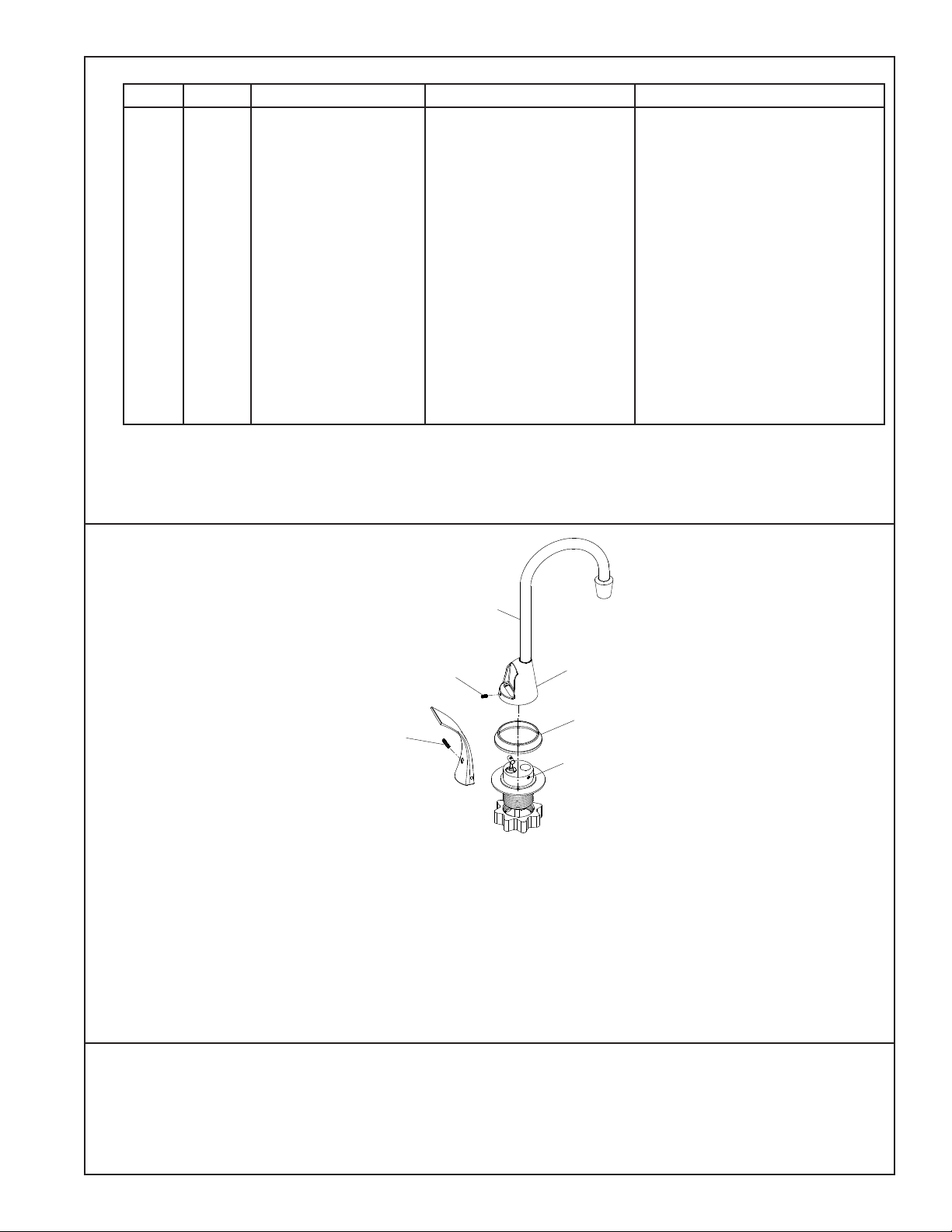
FIG. 8
Faucet Assembly Instructions
1. Place the faucet spout through the chrome cover with the smaller diameter end toward the faucet outlet.
2. Place the chrome collar over the faucet spout with the smaller diameter toward the bigger diameter chrome cover in step no. 1.
3. Place the faucet spout end down inside the same diameter hole in the brass connector.
4. Hold the chrome collar and cover up so you can get to the faucet set screw, turn the faucet spout so it goes toward the drain on the cooler.
5. Tighten the faucet set screw gradually until faucet wil not rotate.
6. Lower the chrome collar and the chrome cover down to basin.
7. Place the chrome cover so the set screw is toward the rear of the faucet.
8. Tighten set screw until cover will not pivot.
9. Place handle on faucet with the slot toward the front of the faucet, slide the slot into the brass pin.
10. Hold handle in snug toward faucet making sure it is seated into the brass pin, and then tighten the handle set screw until
handle will not come off the brass pin.
11. Removal of the handle is exactly opposite of the assembly process.
Faucet Spout
Chrome Cover
Chrome Collar
Faucet Spout
Set Screw
Handle Set
Screw
Cover Set Screw

This manual suits for next models

2

Other Elkay Water Dispenser manuals

Elkay VRCHDTLDD B Series Installation manual

Elkay

Elkay VRCHDTLDD B Series Installation manual

Elkay EWA14 1G Series Installation manual

Elkay

Elkay EWA14 1G Series Installation manual

Elkay EFA8 1L Series Installation manual

Elkay

Elkay EFA8 1L Series Installation manual

Elkay EFAVR Installation manual

Elkay

Elkay EFAVR Installation manual

Elkay ESWA13 1F Series Installation manual

Elkay

Elkay ESWA13 1F Series Installation manual

Elkay VRCD Series Installation manual

Elkay

Elkay VRCD Series Installation manual

Elkay VRCHD8 1B Series Installation manual

Elkay

Elkay VRCHD8 1B Series Installation manual

Elkay EZ Series Installation manual

Elkay

Elkay EZ Series Installation manual

Elkay LVRC8-BAC Series Installation manual

Elkay

Elkay LVRC8-BAC Series Installation manual

Elkay EZOTL Series Installation manual

Elkay

Elkay EZOTL Series Installation manual

Elkay EZSTLG8L Installation manual

Elkay

Elkay EZSTLG8L Installation manual

Elkay EWTLA16*1E Series Installation manual

Elkay

Elkay EWTLA16*1E Series Installation manual

Elkay LZ Series Installation manual

Elkay

Elkay LZ Series Installation manual

Elkay EZSG8WS 1B Series Instructions for use

Elkay

Elkay EZSG8WS 1B Series Instructions for use

Elkay EMABF8WS*1D Series Instructions for use

Elkay

Elkay EMABF8WS*1D Series Instructions for use

Elkay EZSTLDWS 1G Series Instructions for use

Elkay

Elkay EZSTLDWS 1G Series Instructions for use

Elkay ezH2O EZWSMD 1A Series Instructions for use

Elkay

Elkay ezH2O EZWSMD 1A Series Instructions for use

Elkay EBFATLDD A Series Installation manual

Elkay

Elkay EBFATLDD A Series Installation manual

Elkay EMABF8 Series Instructions for use

Elkay

Elkay EMABF8 Series Instructions for use

Elkay HTHBHVR8BL Series User manual

Elkay

Elkay HTHBHVR8BL Series User manual

Elkay FLEXI-GUARD Deluxe EFHA14 Series Installation manual

Elkay

Elkay FLEXI-GUARD Deluxe EFHA14 Series Installation manual

Elkay OFA25*2FJO Installation manual

Elkay

Elkay OFA25*2FJO Installation manual

Elkay EFA4 1F Series Installation manual

Elkay

Elkay EFA4 1F Series Installation manual

Elkay LVRCHD8S Installation manual

Elkay

Elkay LVRCHD8S Installation manual

Popular Water Dispenser manuals by other brands

Weco HYDRA Series manual

Weco

Weco HYDRA Series manual

Rayne 5066 owner's manual

Rayne

Rayne 5066 owner's manual

Franke KEM8SCP quick start guide

Franke

Franke KEM8SCP quick start guide

Nippon Magnetis CG Series instruction manual

Nippon Magnetis

Nippon Magnetis CG Series instruction manual

Brita Wave BPA-Free Water Pitcher user guide

Brita

Brita Wave BPA-Free Water Pitcher user guide

Bunn H5M OPERATING & SERVICE MANUAL

Bunn

Bunn H5M OPERATING & SERVICE MANUAL

Osmio Duo Hydrogen instruction manual

Osmio

Osmio Duo Hydrogen instruction manual

Intermountain Water Imperial owner's manual

Intermountain Water

Intermountain Water Imperial owner's manual

Bunn ThermoFresh SERVER Use & care information

Bunn

Bunn ThermoFresh SERVER Use & care information

Rinnai RBBW1500 Owner and installer guide

Rinnai

Rinnai RBBW1500 Owner and installer guide

AQUA-LITY AC Installation, use and maintenance handbook

AQUA-LITY

AQUA-LITY AC Installation, use and maintenance handbook

Delta ESCALDA installation guide

Delta

Delta ESCALDA installation guide

Tier1 H2-35 owner's manual

Tier1

Tier1 H2-35 owner's manual

mysoda Oasis Evo instruction manual

mysoda

mysoda Oasis Evo instruction manual

AL Tech Primeo manual

AL Tech

AL Tech Primeo manual

ThePondguy AllClear PLUS 3600 Installation & maintenance

ThePondguy

ThePondguy AllClear PLUS 3600 Installation & maintenance

Eco Pure EP100 Installation and operation manual

Eco Pure

Eco Pure EP100 Installation and operation manual

Pure-Pro ERO-M7 user manual

Pure-Pro

Pure-Pro ERO-M7 user manual

manuals.online logo
manuals.online logoBrands
  • About & Mission
  • Contact us
  • Privacy Policy
  • Terms and Conditions

Copyright 2025 Manuals.Online. All Rights Reserved.