manuals.online logo
Brands
  1. Home
  2. •
  3. Brands
  4. •
  5. Elkay
  6. •
  7. Water Dispenser
  8. •
  9. Elkay LZO8TLx1C Installation manual

Elkay LZO8TLx1C Installation manual

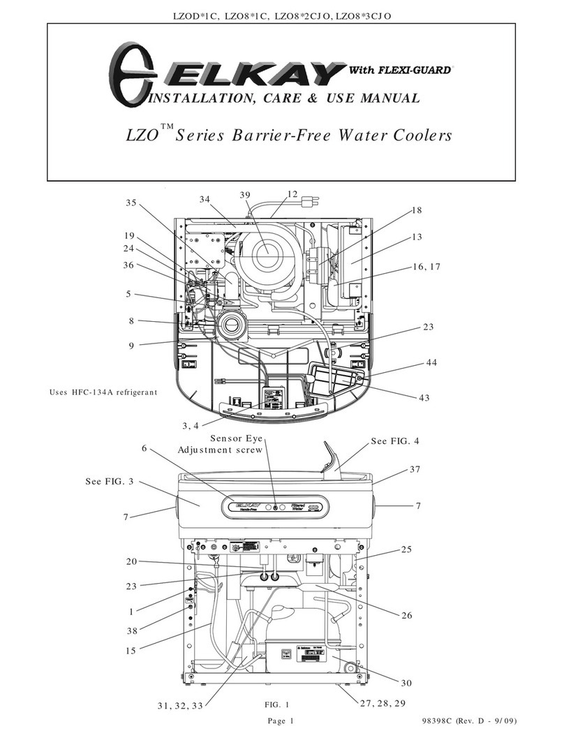
LZO8TL*1C, LZO8TL*2C, LZO8TL*3C
98399C (Rev. C - 03/09)
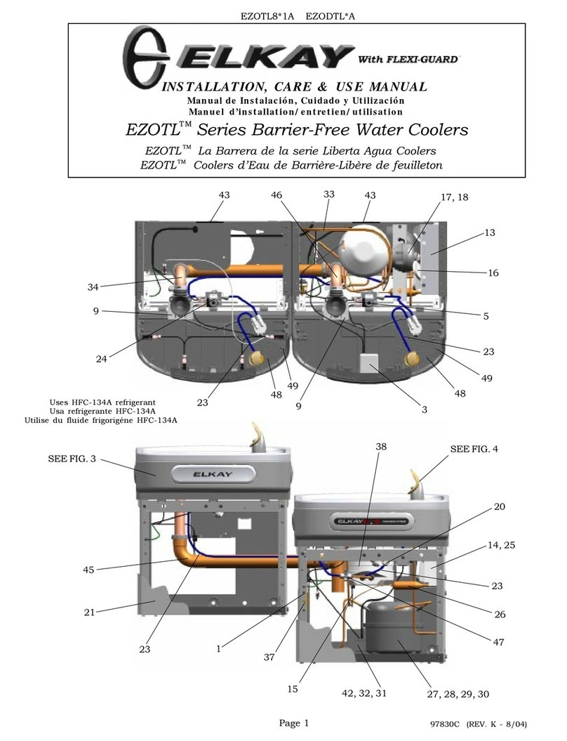
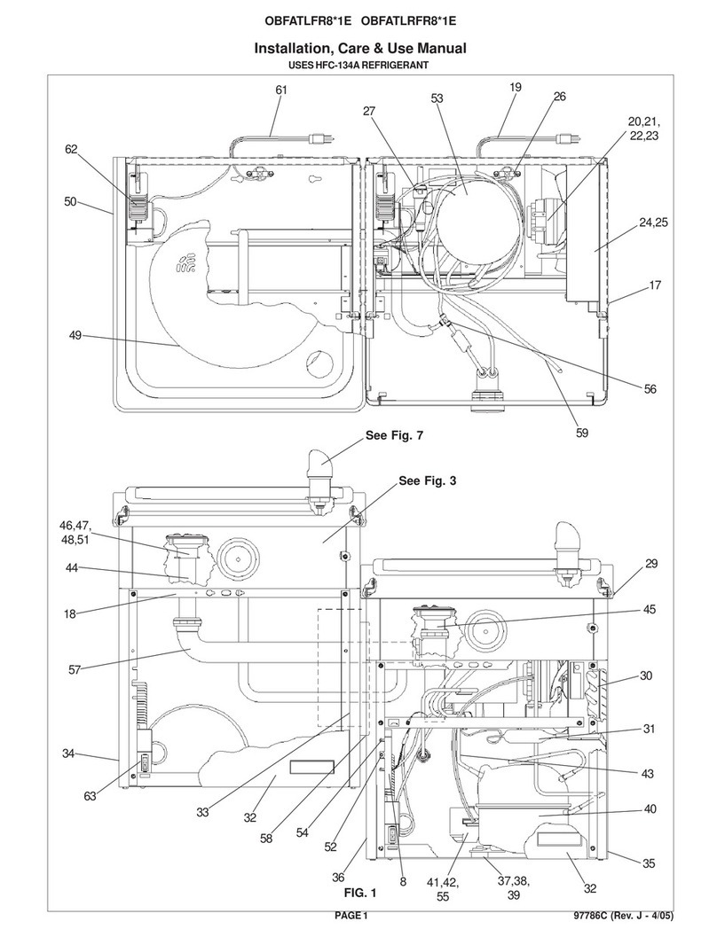
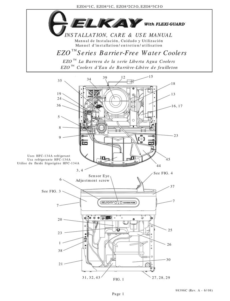
LZOTL Series Barrier-Free Water Coolers
INSTALLATION, CARE & USE MANUAL
TM
Page 1
Uses HFC-134A
refrigerant 3, 4
5
7
8
13
25
15
16, 17
18
19
21
24 26
27, 28, 29
30
31, 32, 43
3435
36
37
38
39
Sensor Eye
Adjustment screw See FIG. 4
9
44
46
6
20
23
See FIG. 3
48
44
33
FIG. 1
12
51
98399C (Rev. C - 03/09)
LZO8TL*1C, LZO8TL*2C, LZO8TL*3C
LEGEND/LEYENDA/LÉGENDE
A = RECOMMENDED WATER SUPPLY LOCATION 3/8 O.D. UNPLATED COPPER TUBE CONNECT STUB WITH SHUT OFF (BY OTHERS) 3 IN. (76mm) MAXIMUM OUT FROM WALL
La UBICACION 3/8 O RECOMENDADA de ABASTECIMIENTO DE AGUA. D. El TUBO del COBRE de UNPLATED CONECTA TALONARIO CON APAGO (POR OTROS) 3 en. (76 Mm) el MAXIMO
FUERADEPARED
L’O.D de 3/8 d’EMPLACEMENT DE PROVISION D’EAU RECOMMANDE. LE TUBE DE CUIVRE DE UNPLATED CONNECTE STUB AVEC ETEINT (PAR LES AUTRES) 3 dans. (76 mm) le MAXIMUM
HORS DU MUR
B = RECOMMENDED LOCATION FOR WASTE OUTLET 1-1/4” O.D. DRAIN STUB 2 IN. OUT FROM WALL
UBICACIÓN RECOMENDADA PARA EL DRENAJE DE SALIDA DE AGUA, DE 1¼” DE DIÁMETRO. El TALONARIO 2 FUERA DE PARED
EMPLACEMENT RECOMMANDÉ POUR LE DRAIN DE D.E. 1-1/4" DE SORTIE D’EAU. STUB 2 HORS DU MUR
C = 1-1/4 TRAP NOT FURNISHED
PURGADOR DE 1¼ NO PROPORCIONADO
SIPHON 1-1/4 NON FOURNI
D = ELECTRICAL SUPPLY (3) WIRE RECESSED BOX
CAJA RECESIVA DE ALAMBRES (3) DE SUMINISTRO ELÉCTRICO
BOÎTE ENCASTRÉE D’ALIMENTATION ÉLECTRIQUE (3) FILS
E = INSURE PROPER VENTILATION BY MAINTAINING 6" (152 mm) (MIN.) CLEARANCE FROM CABINET LOUVERS TO WALL.
ASEGURE UNA VENTILACIÓN ADECUADA MANTENIENDO UN ESPACIO E 6" (152 mm) (MÍN.) DE HOLGURA ENTRE LA REJILLA DE VENTILACIÓN DEL MUEBLE Y LA PARED
ASSUREZ-VOUS UNE BONNE VENTILATION EN GARDANT 6" (152 mm) (MIN.) ENTRE LES ÉVENTS DE L’ENCEINTE ET LE MUR.
F = 7/16 BOLT HOLES FOR FASTENING UNIT TO WALL
AGUJEROS DE LAS TUERCAS DE 7/16 PARA SUJETAR LA UNIDAD A LA PARED
TROUS D’ÉCROUS 7/16 POUR FIXER L’APPAREIL AU MUR
FIG. 2
Page 2
19"
483mm
8 1/16"
204mm
1 7/16"
37mm
12 1/2"
318mm
27"
686mm
ADA
REQUIREMENT
32 7/8"
835mm
ORIFICE
HEIGHT
38 3/8"
975mm
ORIFICE
HEIGHT
31 5/16"
796mm
RIM
HEIGHT
3"
76mm
C
HANGER
BRACKET
*
*
*
*
*
13 15/16"
354mm
17 7/16"
443mm
19"
483mm
21 7/8"
556mm
22 15/16"
583mm
24 1/2"
622mm
34 5/16"
872mm
2"
51mm
28 13/16"
732mm
2"
51mm
18 3/8"
467mm
6 3/8"
162mm
6 3/8"
162mm
6 3/8"
162mm
6 3/8"
162mm
2"
51mm
5 3/4"
146mm
7"
178mm
7"
178mm
2"
51mm
7/8"
22mm
3 7/8"
98mm
B
A (ALT. LOCATION)
A (PREFERRED
LOCATION)
F
F
D (ALT. LOCATION)
D (PREFERRED
LOCATION)
18 3/8"
467mm
O9/32"
7mm (6)
*
*
*
*
*
*
*
*
E
E
FINISHED FLOOR
PISOACABADO
PLANCHERFINI
REDUCE HEIGHT BY 3 INCHES FOR INSTALLATION OF CHILDRENSADACOOLER
*
*ADA REQUIREMENT
*REQUISITODE A.D.A.
*EXIGENCEADA
LZO8TL*1C, LZO8TL*2C, LZO8TL*3C
98399C (Rev. C - 03/09)
HANGER BRACKETS & TRAP
INSTALLATION
1) Remove hanger bracket fastened to back of cooler by removing one (1) screw.
2) Mount the hanger bracket as shown in Figure 2.
NOTE: Hanger Bracket MUST be supported securely. Add fixture support carrier if wall will not provide adequate support. Anchor hanger securely to wall
using all six (6) 1/4 in. dia. mounting holes.
IMPORTANT:
5-7/8 in. (150mm) dimension from wall to centerline of trap must be maintained for proper fit.
INSTALLATION OF COOLER
3) Hang the cooler on the hanger bracket. Be certain the hanger bracket is engaged properly in the slots on the cooler back as shown in Figure 2.
4) Remove the four (4) screws holding the lower front panel at the bottom of cooler. Remove the front panel by pulling straight down and set aside.
5) Connect water inlet line--See Note 4 of General Instructions.
6) Install trap. Remove the slip nut and gasket from the trap and install them on the cooler waste line making sure that the end of the waste line fits into the
trap. Assemble the slip nut and gasket to the trap and tighten securely. The purple jumper wire (item 48) from the right hand refrigerated unit is to be
connected to the the purple jumper wire (item 48) located on the non-refrigerated left hand unit by removing the protective end caps and connecting the
male and female terminal connectors.
IMPORTANT: If it is necessary to cut the drain, loosen the screw at the black rubber boot and remove tube, check for leaks after re-assembly.
7) Plug in electrical power. Unit must have
electrical power to have water flow. START UP
Also See General Instructions
8) Stream height is factory set at 35 PSI. If supply pressure varies greatly from this, adjust screw located on the left side below the push bar assembly on
the crossbar. CW adjustment will raise stream and CCW adjustment will lower stream. For best adjustment, stream should hit basin approximately 6-
1/2” (165mm) from bubbler on the downward slope of the basin.
NOTE: If continuous flow occurs at the end of the compressor cycle, turn cold control (Item 38) counterclockwise 1/4 turn.
9) Replace the front panel ensuring that the metal wrapper is secured inside of the upper shroud. Replace all four screws previously removed.
Page 3
SENSOR RANGE ADJUSTMENT:
The electronic sensor used in this cooler is factory pre-set for a “visual” range of 36 inches (914 mm). If actual
range varies greatly from this or a different setting is desired, follow the range adjustment procedure below:
- Using a small tip screwdriver, locate range adjustment screw through the small hole between the sensor
lenses (See Page 1.) Turn this screw clockwise to increase range and counterclockwise to decrease range
(See Fig. 3).
CAUTION: Complete range of sensor (24-36 inches/610-1168mm) is only one turn of the adjusting
screw.
SENSOR WITH VISUAL FILTER MONITOR (VFM) – LZO SERIES:
The electronic sensor includes LED filter status indicators that are factory preset to monitor filter life. The sensor monitors the “ON” time of the water
valve solenoid and keeps track of total time water is dispensed. On LZOTL units, the sensor also monitors the water time on of the left hand unit
using a purple jumper wire. If the purple jumper wire is not installed, improper water usage will be calculated. There are (3) LED’s and indicates the
following: Green LED (Good) indicates that the filter is operating within 0% - 80% of its life.
Yellow LED indicates that the filter is operating within 80% - 100% of its life.
Red LED (Replace) indicates that the filter needs to be replaced since it has reached end of filter life.
Once power is applied to the water cooler, if all three LED’s flash then the Green LED aluminates, this indicates that there is some filter usage memory
stored. When the Green LED comes on only, this indicates that the filter life is at absolute 0% of filter life. NOTE: You may have some very minimal
filter life in memory upon receiving water cooler due to factory functional testing.
NOTE: The filter status will be retained until reset (see resetting filter monitor). The filter monitor will retain its memory even during a loss
of power.
RESETTING VISUAL FILTER MONITOR (VFM):
In order to reset the visual filter monitor status LED’s, you must remove the access panel (item 45) underneath the front dispenser. With your finger
or straight blade screw driver, reach inside opening and depress the reset button located on the back of the sensor for a minimum of 1 second. (You
may need a flashlight) Reinstall access panel and the Green LED should be illuminated indicating that the visual filter monitor has been reset.
SENSOR CONTROL: If sensor fails to operate valve mechanism or operates erratically, check the following.
A. Ensure there are no obstructions within a 40 inch (1016mm) radius in front of cooler.
B. Check wire connections at the solenoid valve and sensor. CAUTION: Make sure unit is unplugged
before checking any wiring.
C. Ensure proper operation of solenoid valve. If there is an audible clicking sound yet no water flows,
look for an obstruction in the valve itself or elsewhere in the water supply line.
98399C (Rev. C - 03/09)
LZO8TL*1C, LZO8TL*2C, LZO8TL*3C
Lower and Upper Shroud
To access the refrigeration system and plumbing connections, remove four screws
from bottom of cooler to remove the lower shroud. To remove the upper shroud for
access to the pushbars, regulator, solenoid valve or other components located in the
top of the unit, remove lower shroud, disconnect drain, remove four screws from tabs
along lower edge of upper shroud, unplug two wires and water tube.
Bubbler
To remove the bubbler, first disconnect the power supply. The underside of the
bubbler can be reached through the access panel (Item 45) on the underside of the
upper shroud (item 2). Remove the access panel by removing the retaining screw (item
46) . To remove the bubbler, loosen locknut (Item 10) from the underside of the
bubbler and remove the tubing from the quick connect fitting per the Operation Of
Quick Connect Fittings section in the General Instructions. After servicing, replace the
access panel and retaining screw.
Service Instructions
BUBBLER DETAIL
NOTE:
When installing replacement bubbler and pedestal, tighten
nut (Item 10) only to hold parts snug in position. Do Not
Overtighten.
Basin
FIG. 3
40 22
41
42
10
37
Bubbler
Assembly
36
8
7
35
7
3
6
2
Sensor Eye
Adjustment Screw
Page 4
FIG. 4
9
45
46
10
47
Cleaning the strainer
To clean the strainer, unscrew the cap of the
solenoid valve. Remove screen and rinse
thoroughly with water. Insert screen back
into solenoid valve and screw cap on. Make
sure the o-ring is placed properly.
Screen
O-ring
Cap
Warm, soapy water or mild household cleaning products can be
used to clean the exterior panels of the EZ coolers. Extra caution
should be used to clean the mirror finished stainless steel panels.
They can be easily scratched and should only be cleaned with mild
soap and water or Windex glass cleaner and a clean, soft cloth
Use of harsh chemicals or petroleum based or abrasive cleaners
will void the warranty.
CLEANING
4
49
50
11 14
LZO8TL*1C, LZO8TL*2C, LZO8TL*3C
98399C (Rev. C - 03/09)
BLK
COLD
CONTROL
GND
FAN
WHT
RED
SENSOR
WHT
BLK
2
3
1
5
6
M
S
C
3
12
MALE TERMINAL ON
WHITE SHORT LEAD
ON POWERCORD
OVERLOAD
COMPRESSOR
RELAY
SOLENOID
VALVE
PURPLE
YELLOW
BLACK
RED
WHITE
GREEN
LED PCB
TO "L" TERMINAL ON POWER INLET TO "N" TERMINAL
ON POWER INLET
TO "GROUND" TERMINAL
ON POWER INLET
GND
GREEN
PURPLE JUMPER
TO DUMMY UNIT
Page 5
WIRING DIAGRAM - EZO 230V
15
18
19
*30
42
31
46
NS
NS
36066C
31431C
33133000
36092C
36085C
36174C
36195C
36050C
36248C
28030C
35826C
Power Cord
Fan Motor
Adapt - Tab .250
Compressor Serv. Pak (230v/60Hz)
Compressor Serv. Pak (230v/50Hz)
Overload (230v/60Hz)
Overload (230v/50Hz)
Relay
Valve - Solenoid
Brkt - Power Inlet
Inlet Power
230V PARTS LIST
ITEM NO. PART NO. DESCRIPTION
2
1
4
7
6
5
3
FIG. 5
DESCRIPTION
1
2
3
4
5
6
7
ITEM NO. PART NO.
51294C
70792C
70823C
70822C
51299C
70818C
22490C
Filter Head Assy.
Screw #8-18 x .75 PH
Fitting - Superseal 3/8” (10 mm)
Fitting - Superseal 1/4” (6 mm)
Filter Assy
Elbow - 3/8” (10mm)
Bracket
WATERSENTRY® FILTER PARTS LIST
(See Fig. 5)
WATERSENTRY®Filter Detail
3
98399C (Rev. C - 03/09)
LZO8TL*1C, LZO8TL*2C, LZO8TL*3C
BLK
COLD
CONTROL
GND
FAN
WHT
RED
SENSOR
WHT
BLK
2
3
1
5
6
M
S
C
3
12
MALE TERMINAL ON
WHITE SHORT LEAD
ON POWERCORD
OVERLOAD
COMPRESSOR
RELAY
SOLENOID
VALVE
PURPLE
YELLOW
BLACK
RED
WHITE
GREEN
LED PCB
GND
GREEN
PURPLE JUMPER
TO DUMMY UNIT
111411443890
56228C
36263C
38417001
36004C
56282C
56074C
56118C
56182C
75580C
66654C
45874C
56237C
56082C
35978C
30664C
70018C
31490C
33133000
66723C
27862C
27864C
40322C
56092C
36247C
66743C
66703C
101474551730
100806740570
19037000
36094C
35959C
35768C
27854C
27852C
66576C
66776C
70444C
55001109
31513C
66533C
66534C
56073C
56011C
55997C
36158C
28401C
56213C
75532C
98169C
36265C
75710C
98368C
66720C
28021C
28020C
Screw - #8-36 x .38 Tri-lobed
Assembly Shroud - Upper
Sensor - VFM
Screw - #10 x .37 PHTC
Wire - Jumper
Pushbar - Front
Pushbar - Side
Drain Fitting
Adapter - Drain
Nut Lock 3/8 x 18
Regulator
TL Waste Line
Shroud - Fan
Nut - Regulator
Power Cord
Fan Blade
Hex Nut - Fan Blade
Fan Motor
Adapt - Tab .250
Tube - Evap. to Base
Wrapper - Stainless TL (R)
Wrapper - Light Grey TL (R)
Orifice Assy.
Poly Tubing (Cut to Length)
Valve - Solenoid
Condenser
Drier
Stud - Compressor Mtg.
Grommet - Compressor Mtg.
Clip - Compressor Mtg.
Compressor Serv. Pack EMI70HNR
Relay
Cover - Relay
Wrapper - Stainless TL (L)
Wrapper - Light Grey TL (L)
Heat Exchanger
Drain Tube TL
Clamp - Drain Fitting
Basin - Stainless Steel
Cold Control
Evaporator Assy. (4 GPH)
Evaporator Assy. (8 GPH)
Bubbler Assy.
Housing Assy.
Pedestal
Overload
Hanger Bracket
Panel - Access
Screw - #10-16 x .63 THSM
Kit - Replacement Cap/Screen/O-Ring
Jumper Wire (Purple)
2-28 x .250 48-2 Plastite Screw
Namplate Label - LZO-VFM
drain Tube TL
Wrapper - Filler Stainless
Wrapper - Filler Light Grey
PART NO. DESCRIPTION
1
2
3
4
5
6
7
8
9
10
11
12
13
14
15
16
17
18
19
20
21
22
23
24
25
26
27
28
29
30
31
32
33
34
35
36
37
38
39
40
41
42
43
44
45
46
47
48
49
50
51
NS
ITEM NO.
115V PARTS LIST
*
PRINTED IN U.S.A.
IMPRESO EN LOS E.E.U.U.
IMPRIMÉ AUX É.-U.
FOR PARTS, CONTACT YOUR LOCAL DISTRIBUTOR OR CALL 1.800.323.0620
PARA PIEZAS, CONTACTE A SU DISTRIBUIDOR LOCAL O LLAME AL 1.800.323.0620
POUR OBTENIR DES PIÈCES, CONTACTEZ VOTRE DISTRIBUTEUR LOCAL OU COMPOSEZ LE 1.800.323.0620
ELKAY MANUFACTURING COMPANY • 2222 CAMDEN COURT • OAK BROOK, IL 60523 • 630.574.8484
*INCLUDES RELAY & OVERLOAD. IF UNDER WAR-
RANTY, REPLACE WITH SAME COMPRESSOR USED
IN ORIGINAL ASSEMBLY.
NOTE: All correspondence pertaining to any of the
above water coolers or orders for repair parts MUST
include Model No. and Serial No. of cooler, name and
part number of replacement part.
115V WIRING DIAGRAM
Page 6
REPAIR SERVICE INFORMATION TOLL FREE NUMBER 1.800.260.6640
NÚMERO GRATIS DE SERVICIO 1.800.260.6640
INFORMATIONS POUR LE SERVICE PAR NUMERO SANS FRAIS 1.800.260.6640

This manual suits for next models

2

Other Elkay Water Dispenser manuals

Elkay EWTLA8 1C Series Installation manual

Elkay

Elkay EWTLA8 1C Series Installation manual

Elkay EZTL Series Installation manual

Elkay

Elkay EZTL Series Installation manual

Elkay EZO8WS 1A Series Instructions for use

Elkay

Elkay EZO8WS 1A Series Instructions for use

Elkay EFA4 1D Series Installation manual

Elkay

Elkay EFA4 1D Series Installation manual

Elkay EZS8WSVRL2K Instructions for use

Elkay

Elkay EZS8WSVRL2K Instructions for use

Elkay VRCHD8 Series Installation manual

Elkay

Elkay VRCHD8 Series Installation manual

Elkay EFAVR Installation manual

Elkay

Elkay EFAVR Installation manual

Elkay EZOTL Series Installation manual

Elkay

Elkay EZOTL Series Installation manual

Elkay LZOTL Series Installation manual

Elkay

Elkay LZOTL Series Installation manual

Elkay LVRCGRNTL8 1B Series Installation manual

Elkay

Elkay LVRCGRNTL8 1B Series Installation manual

Elkay EMABFDTL C Series Installation manual

Elkay

Elkay EMABFDTL C Series Installation manual

Elkay OFA25*2FJO Installation manual

Elkay

Elkay OFA25*2FJO Installation manual

Elkay OFAVR14*1 Installation manual

Elkay

Elkay OFAVR14*1 Installation manual

Elkay EFOA8 1D Installation manual

Elkay

Elkay EFOA8 1D Installation manual

Elkay VRCHD8 Series Guide

Elkay

Elkay VRCHD8 Series Guide

Elkay VRCHD8 1A Series Installation manual

Elkay

Elkay VRCHD8 1A Series Installation manual

Elkay EZ Series Installation manual

Elkay

Elkay EZ Series Installation manual

Elkay EZTL Series Installation manual

Elkay

Elkay EZTL Series Installation manual

Elkay EWA14 3GJO Series Installation manual

Elkay

Elkay EWA14 3GJO Series Installation manual

Elkay LZ Series Installation manual

Elkay

Elkay LZ Series Installation manual

Elkay EZO Series Installation manual

Elkay

Elkay EZO Series Installation manual

Elkay LZO Series Installation manual

Elkay

Elkay LZO Series Installation manual

Elkay VRCTL Series Installation manual

Elkay

Elkay VRCTL Series Installation manual

Elkay LZO8TL 1D Series Installation manual

Elkay

Elkay LZO8TL 1D Series Installation manual

Popular Water Dispenser manuals by other brands

Home HME030236N manual

Home

Home HME030236N manual

Viqua FB1-34PR-DO instruction sheet

Viqua

Viqua FB1-34PR-DO instruction sheet

Fetco HWB-5 user guide

Fetco

Fetco HWB-5 user guide

Reflex Fillsoft operating instructions

Reflex

Reflex Fillsoft operating instructions

Water Soft ISOBAR III Installation & operation manual

Water Soft

Water Soft ISOBAR III Installation & operation manual

Columbia aqua FC-400-ROP Service manual

Columbia

Columbia aqua FC-400-ROP Service manual

WaterLogic WL100 user guide

WaterLogic

WaterLogic WL100 user guide

Panasonic NCJD40C operating instructions

Panasonic

Panasonic NCJD40C operating instructions

Halsey Taylor SW Series owner's manual

Halsey Taylor

Halsey Taylor SW Series owner's manual

Whirlpool WHES3T Installation and operation manual

Whirlpool

Whirlpool WHES3T Installation and operation manual

Hydrotech 565BM-75 Installation and operation manual

Hydrotech

Hydrotech 565BM-75 Installation and operation manual

Avantco Equipment 177HWD10 user manual

Avantco Equipment

Avantco Equipment 177HWD10 user manual

Zontos 750 user manual

Zontos

Zontos 750 user manual

Airwater Nordik instruction manual

Airwater

Airwater Nordik instruction manual

Judo QUICKSOFT-P Installation and operating instructions

Judo

Judo QUICKSOFT-P Installation and operating instructions

Kambrook Aquarius KWF20 manual

Kambrook

Kambrook Aquarius KWF20 manual

BRIO CLPOU720UVF3 Setup manual

BRIO

BRIO CLPOU720UVF3 Setup manual

Brita PURITY 600 Steam manual

Brita

Brita PURITY 600 Steam manual

manuals.online logo
manuals.online logoBrands
  • About & Mission
  • Contact us
  • Privacy Policy
  • Terms and Conditions

Copyright 2025 Manuals.Online. All Rights Reserved.