Elli Audi Wallbox User manual

EN ES PL EL
Powered by
Audi Wallbox
Manual – Part A
English
2

Contents
General information and scope 04
General information and scope 04
General 04
Safety precautions 05
Technical specifications 08
Product information 10
Charge with the wallbox 12
Start and stop a charging session 13
Status indication 14
Prepare for installation 18
Content of delivery 18
Prerequisites for installation 19
Tools and material needed 21
Notice on installation 23
Install wallbox 25
Install wall bracket 26
Prepare main assembly for installation 26
Mount main assembly onto wall bracket 27
Assemble wallbox 27
Set DIP-switches 30
Configure Audi Wallbox plus and
Audi Wallbox pro 36
GDPR disclaimer 36
Configure the Audi Wallbox plus and
Audi Wallbox pro locally 39
Pair Audi Wallbox plus and
Audi Wallbox pro to App account 40
Commissioning 41
Maintenance 41
Troubleshooting 42
Error states of the wallbox 42
Adjust the length of the charging cable 47
Decommissioning 48
Disposal 49
Appendix 50
Warranty 50
EU Declaration of conformity 50
Glossary 51
3
English

4
General
information
and scope
Scope of the document
Keep this manual for the entire life cycle of
the product.
The following installation-related and
troubleshooting chapters are intended for
qualified personnel, such as certified electri-
cians, who can correctly and safely install the
wallbox and identify potential danger:
› Chapters: 1, 4, 5, 6, 8, 9, 10, 11 and 12.
The following usage-related chapters are in-
tended for end-users to correctly and safely
operate the wallbox:
› Chapters: 2, 3, 7 and 13.
General
Product and environmental characteristics
Legal information
© 2020 EVBox Manufacturing B.V. - all rights
reserved. Nothing from this document may
be modified, reproduced, processed, or
distributed in any form or by any means, wit-
hout the prior written permission of EVBox.
The charging station has been CE-certified by the manufacturer and
bears the CE logo. The relevant declaration of conformity may be
obtained from the manufacturer.
The charging station complies with the RoHS Directive (RL 2011/65/
EU). The relevant declaration of conformity may be obtained from the
manufacturer.
Electrical and electronic appliances, including accessories, must be
disposed of separately from the general municipal solid waste.
Recycling of materials saves raw materials and energy and makes a
major contribution to conserving the environment.
5
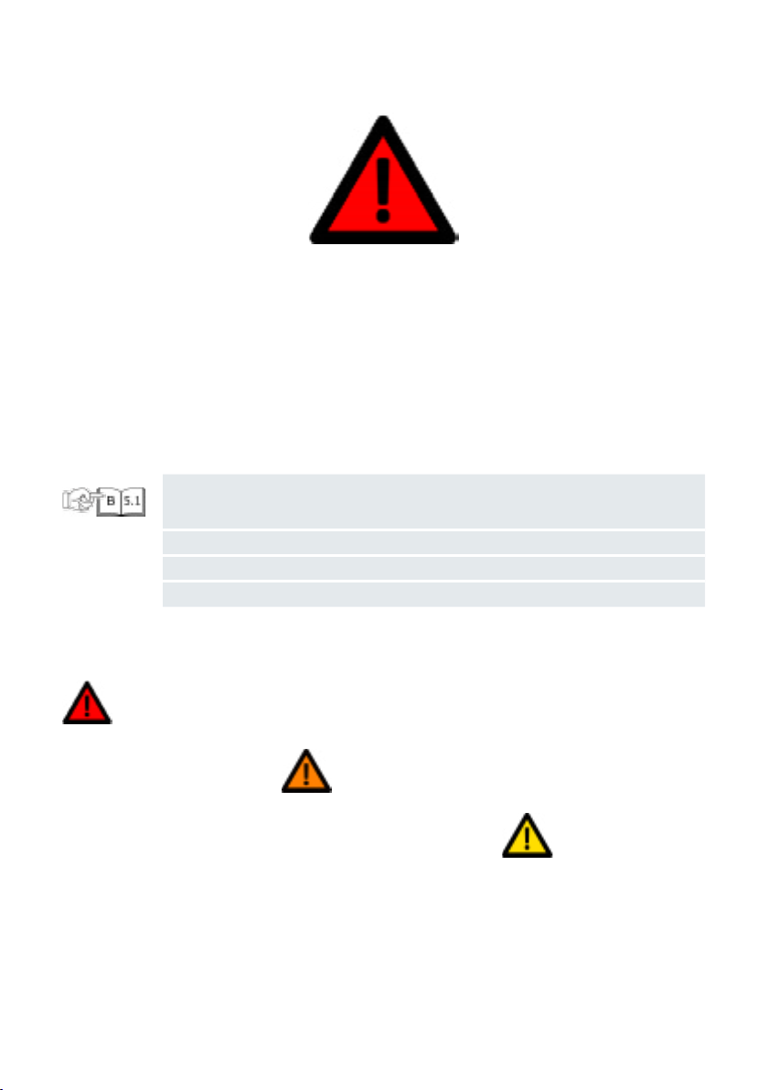
Symbols
The symbols used in this manual have the following meaning:
Symbols used and their explanations
Safety precautions
Read and obey the following safety precautions before you install, service or use your
charging station. A qualified electrician must ensure that the charging station is installed in
accordance with the relevant country-specific standards and local regulations.
Please note that only qualified electricians may perform installation and maintenance in
accordance with local regulations and the standards applicable in the specific country!
1., a. oder I.
-
Note:
Highlighted sections
Danger
Texts with this symbol
contain information regar-
ding hazardous situations
which will cause death or
severe injures if ignored. Texts with this symbol
contain information regar-
ding hazardous situations
which could cause death or
severe injuries if ignored.
Warning
Caution
Texts with this symbol con-
tain information regarding
hazardous situations which
could cause minor or mo-
derate injuries if ignored.
This symbol indicates that the illustrations corresponding to the indicated
chapter are to be found in manual B.
Actions to be followed in the stated order.
Actions to be followed in a non-specific order.
Texts with this symbol contain supplementary information.
English

6
Please note that only qualified electricians
may perform installation and maintenance
in accordance with local regulations and
the standards applicable in the specific
country!
Operating the wallbox when it indicates an
error state, or when the wallbox or the char-
ging cable have cracks, show extensive wear,
or other physical damage, will result in the
risk of electric shock, which will cause severe
injuries or death.
› Do not operate the wallbox if it is physically
damaged.
› In the event of danger and/or an accident,
a certified electrician must immediately
disconnect the electrical supply from the
wallbox.
› See chapter Troubleshooting for explana-
tion and further instructions on indicated
error states.
tor if you suspect that the wallbox or cable
is damaged.
Some electric vehicles release hazardous or
explosive gasses when charging which will
result in the risk of explosion, and thus cause
severe injuries or death.
› Refer to your vehicle user manual to check
if your vehicle releases hazardous or explo-
sive gases when charging.
› Follow the instructions given in the vehicle
user manual before choosing the location
of the charging station.
Extensive exposure of the wallbox to water
or handling the wallbox with wet hands will
result in the risk of electric shock, which will
cause severe injuries or death.
› Do not direct powerful jets of water toward
or onto the wallbox.
› Never operate the wallbox with wet hands.
› Do not put the charging plug into any
liquid.
Not following the installation instructions
given in this manual will result in the risk
of electric shock to users, which will cause
severe injuries or death.
› Read this manual before installing the
wallbox.
› If you are unsure about how to use the
wallbox after reading this manual, ask for
dealer for more information.
› Do not allow children to operate the wall-
box. Adult supervision is required when
children are near a wallbox that is in use.
Servicing of the wallbox or its components
by non-qualified personnel will result in the
risk of electric shock and damage to the
wallbox, which will cause severe injury or
death.
› The user must not attempt to service or
repair the wallbox as it does not contain
user-serviceable parts.
› The wallbox must only be serviced, repaired
or relocated by a qualified electrician.
Danger
The following sections contain general information that applies when installing and
using the wallbox.

7
Improper usage of the wallbox may result
in damage to the wallbox, which may cause
injury or death.
› Read this manual before using the wallbox.
› If you are unsure about how to use the
wallbox after reading this manual, ask for
dealer for more information.
› Do not allow children to operate the wall-
box. Adult supervision is required when
children are near a wallbox that is in use.
Using adapters, conversion adapters or cord
extensions with the wallbox may result in
technical incompatibilities and can result
in damage to the wallbox, and thus cause
injuries or death.
› Use this charging station to charge Mode 3
compatible electric vehicles only.
› Refer to your vehicle user manual to check
if your vehicle is compatible.
Exposure of the wallbox to heat sources or
flammable substances can result in damage
to the wallbox, and thus cause injuries or
death.
› Make sure that the wallbox or the charging
cable never come into direct contact with
heat sources.
› Do not use explosive or readily flammable
substances near the wallbox.
Using the wallbox under conditions not spe-
cified in this manual may result in damage
to the wallbox, which may cause injury or
death.
› Only use the wallbox under the specified
operating conditions, see chapter Technical
specifications.
Charging the electric vehicle with the char-
ging cable not being completely unwound
may result in overheating of the cable, which
can damage the wallbox.
› Make sure to completely unwind the
charging cable and avoid overlapping loops
before charging your electric vehicle.
Putting fingers into or leaving other objects
inside the plug port (for example during
cleaning) may cause injury or damage to the
wallbox.
› Do not put your fingers into the plug port.
› Do not leave objects inside the plug port.
Use of devices with (electro) magnetic
properties in the vicinity of the wallbox may
cause damage to the wallbox and affect its
operation.
› Keep and use (electro) magnetic devices a
safe distance from the wallbox.
Transport and storage
› Disconnect input power before removing
the charging station for storage or reloca-
tion.
› Only transport and store the charging
station in its original packaging. No liability
can be accepted for damage incurred when
the product is not transported in its origi-
nal packaging.
› Store the charging station in a dry environ-
ment in the temperature range given in the
specifications.
Warning Caution
English

8
Electrical properties
Connection capacity 1-phase, 230 V, 32 A, 50 Hz. 3-phase, 400 V, 16 A, 50 Hz.
Charging capacity 7.4 kW (1-phase - 32 A). 11 kW (3-phase - 16 A).
Charge mode Mode 3 (IEC 61851) - ISO 15118*.
Fixed charging cable Type 2 plug (IEC 62196-2).
Number of fixed
charging cables 1.
Charging cable length 4.5 m or 7.5 m.
Installation wiring 16 A installation input
terminals: 1 - 6 mm².
32 A installation input
terminals: 1 - 10 mm².
Metering Optional, for Audi Wallbox pro.
Safety and certification
Upstream installation
protection
Minimum dedicated 1-phase 32 A (32 A station) or 3-phase 16 A
(16 A station) upstream circuit breaker and at minimum RCD type
A (30 mA AC). Check local installation requirements if additional
measures are required.
Static power limitation Via DIP-switches.
Earth leakage sensor
(ELS) 6 mA DC
Ground loss monitor
Physical connection m quality onitoring, without
ground monitoring
Via CT coils - optional comfort feature.
Invasive / non-Invasive - 40 A - 200 A,
brands: VAC, LEM, and Nidec.
See chapter Set DIP-switches for the supported models.
Operating temperature
range -30 °C - +50 °C.
Storage temperature
range -30 °C - +85 °C.
Operating humidity Max. 95 % - non-condensing.
Maximum installation
height Max. 4000 m above sea level.
Enclosure ratings IP54 (IEC 60529), IK10 (IEC 62262).
Certification See EU Declaration of conformity
Technical specifications

9
Safety Class Safety Class I (the charging station is equipped with a ground
terminal for safety) and overvoltage Category III.
Power supply input EV Supply equipment permanently connected to AC supply net-
work.
Normal Environmental
conditions Outdoor use.
Access Equipment for locations with non-restricted access.
Connectivity
Authorization* NFC / RFID (ISO 14443, ISO 15693).
Plug & Charge (ISO 15118).
Status indication / HMI
(Human Machine
Interface)
LED based HMI.
Communication stan-
dard*
Wi-Fi 2.4 / 5 GHz, Ethernet (via RJ45 connection), optional 4G /
LTE.
Communication
protocol to backend* OCPP 2.0J.
Communication pro-
tocol to Home Energy
Management System*
EEBus.
Local configuration* via Configuration Manager.
Physical properties
Housing Polycarbonate.
Front panel Polycarbonate and hardened glass.
Bezel Acrylonitrile Styrene Acrylate (ASA).
Mounting bracket Steel (zinc plated).
Dimensions (W x H x D) 297 mm x 406 mm x 116 mm.
Weight
1-phase 32 A station with 4.5 m charging cable ~ 6 kg.
1-phase 32 A station with 7.5 m charging cable ~7 kg.
3-phase 16 A station with 4.5 m charging cable ~ 6 kg.
3-phase 16 A station with 7.5 m charging cable ~ 7 kg.
Mounting method Stationary equipment, mounted on walls (preferred method),
poles or equivalent positions – surface mounted.
Color Platinum gray with electric white bezel.
* For Audi Wallbox plus and Audi Wallbox pro only.
English

10
Features Audi
Wallbox Audi Wallbox
plus Audi Wallbox
pro
Maximum output power
7.4 kW (1-phase) •••
Maximum output power
11 kW (3-phase) •••
Attached charging cable
Type 2 (4.5 m or 7.5 m) •••
Alternating Current (AC) charging •••
Integrated Direct Current (DC)
fault current detection •••
Wi-Fi / Ethernet communication –• •
LTE mobile network
communication –•* •
Data transfer according to
OCPP 2.0J –• •
Access control with charge card –• •
Remote access via myAudi App –• •
Remote software
update / diagnostic –• •
MID certified power consump-
tion recording and calculation – – •
Product
information
The table below contains the available product configurations for the Audi Wallbox models.
*Option

11
English

Charge with
the wallbox
Warning
› Always check that the wallbox, the char-
ging cable, and the charging plug are free
of damage before starting a charging
session.
› Always check that the contact area of the
charging plug is free from dirt and moistu-
re before starting a charging session.
› Make sure that the charging cable cannot
become damaged (kinked, jammed or
driven over).
› Take precautions so that the charge plug
does not come into contact with heat
sources, dirt or water.
Using a damaged wallbox or a damaged charging cable may expose the user to electric com-
ponents and result in the risk of electric shock, which may cause injury or death.
12

13
Start and stop a charging session
Start charging
Your car is charging.
Stop charging.
Plug the charging cable into
your car.
Optionally, hold your charge
card (RFID card) in front of
the reader on the charging
station to start charging.*
Optionally, hold your charge
card (RFID card) in front of
the reader on the charging
station to stop charging.*
Unplug the charging cable
from your car.
* For Audi Wallbox plus and Audi Wallbox pro only.
English
14
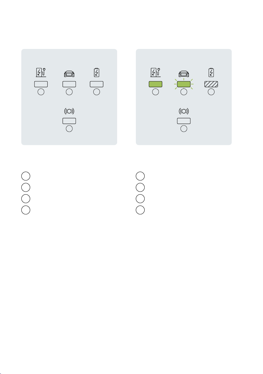
Status indication
Wallbox state
Vehicle state
House state
RFID state
Solid LED
Flashing LED
State remains unchanged
Off
1 5
2 6
3 7
4 8
LED description LED states
21 3
4
5 7
8
6

15
State description Display
Off or energy saving
Wallbox is starting up.
Wait until the wallbox is
ready to charge.*
Configuration Manager
accessible via Wi-Fi
hotspot. Be aware that
charging is not possible
during this state.*
Idle - ready to charge.
Car plugged in, charging
paused by wallbox, App,
or infrastructure. The
charging session will con-
tinue when allowed.
English

16
State description Display
Car plugged in, not char-
ging, car paused / fully
charged.
Car plugged in, waiting
for charge card/NFC input
or remote authorization.*
Car plugged in, charge
card/NFC authorization
pending.*
Authorization / Remote
Start accepted.*

17
State description Display
Car plugged in, charge
card/NFC rejected.*
Plug & Charge
authorization pending.*
Plug & Charge
authorization rejected.*
Car plugged in, charging.
* For Audi Wallbox plus and Audi Wallbox pro only.
NOTE: If the wallbox shows other states than the ones described above, see Error states of
the wallbox for more information.
English
18
Prepare for
installation
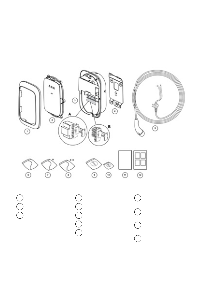
Content of delivery
Bezel
Front cover x 1
Main assembly x 1
A. Audi Wallbox pro
with kWh meter
B. Audi Wallbox or Audi
Wallbox plus with feed-
through terminals
Wall bracket x 1
Charging cable x 1
HMI cable x 1
RFID cable * x 1
RS485 cable ** x 1
Fastening kit for
main assembly x 1
Fastening screws for
front cover x 1
Installation and User
Manual A x 1
Installation
Manual B x 1
1 4 9
2 5
10
11
12
3 6
7
8
* For Audi Wallbox plus and Audi Wallbox pro only.
** For Audi Wallbox pro only.
19
Prerequisites for installation
Your Audi Wallbox pro
comes equipped with a kWh
meter, and it is compatible
with different types of kWh
meters. For example, a
3-phase kWh meter will also
be compatible in a 1-phase
wallbox, as shown in the
following table.
Possible
combinations 1-phase
kWh meter 3-phase
kWh meter
1-phase Audi
Wallbox pro • •
3-phase Audi
Wallbox pro –•
Working on electric installations without
proper precautions will result in the risk of
electric shock, and thus cause severe injury
or death.
› The installation must only be performed by
qualified electricians.
› Make sure that connection of the electrical
power cannot occur during installation.
› Put up caution tape and warning signs
to mark the working areas. Make sure no
unauthorized persons enter the working
areas.
Danger
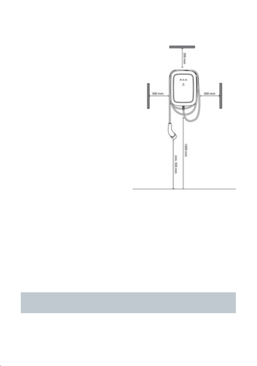
Choose location
› Position the wallbox, where possible, in
surroundings where it is not exposed to ex-
treme sunlight and vulnerable to external
damage.
› The wall must have a flat structure and
must be able to hold a load of at least 100
kg.
› The minimum free space around the wall-
box must be a minimum of 300 mm.
English
20
NOTE: The above illustration indicates a standard installation height. Observe and comply
with the local accessibility regulations.
Pre-installation checklist
› The local installation regulations are identi-
fied and are followed.
› A miniature circuit breaker (MCB) and resi-
dual current device (RCD) must be installed
upstream and have ratings that correspond
to the local power supply as well as to the
required charging power.
› The following installation instructions are
obeyed.
› The recommended tools (additional tools
needed) are available on site. See chapter
Tools and material needed for more infor-
mation.
› The plugs, screws, and drill bits to be used
for mounting the wall bracket are suita-
ble for the wall structure at the place of
installation.
› The bending radius of the power supply
cable is within tolerances during and after
installation.
› The bending radius of the charging cable is
within tolerances during installation and
storage.
› The configuration of the supply cable,
Ethernet cable (optional) and CT coils (op-
tional) is determined.
› The Set DIP-switches chapter is consulted
for the list of supported CT coils.
› A single multi-core cable must be used for
connecting multiple CT coils for overload
protection.
Table of contents
Languages:
Other Elli Automobile Accessories manuals


