Elliott SpeedCut SCT78 Manual

www.elliott-tool.com
Tube & Pipe Cleaners Tube Testers Tube Plugs Tube Removal Tube Installation
SpeedCut
Models SCT78 & SCT98
Operating and Maintenance Instructions


Table Of Contents
Introduction .......................................................................................................... 4
Safety Instructions................................................................................................ 5
Uncrating & Hookup............................................................................................. 7
SpeedCut Overview ............................................................................................. 8
Recommended Spares Kit Components ........................................................... 10
Installation of Accessories.................................................................................. 11
Bundle Setup Instructions.................................................................................. 16
Operating Instructions........................................................................................ 17
Blade Information ............................................................................................... 20
General Information............................................................................................ 21
Notes on Sawing ................................................................................................ 22
Troubleshooting.................................................................................................. 24
Maintenance Instructions ................................................................................... 31
Adjustment & Repair .......................................................................................... 34
Technical Drawings ............................................................................................ 36
Technical Information ......................................................................................... 37
Know Your Responsibility................................................................................... 38
Warranty ............................................................................................................. 39

4 SpeedCut
Introduction
Thank you for purchasing this Elliott product. More than 100 years of experience have been employed
in the design and manufacture of our products, representing the highest standard of quality, value and
durability. Elliott tools have proven themselves in thousands of hours of trouble free eld operation.
If this is your rst Elliott purchase, welcome to our company; our products are our ambassadors.
If this is a repeat purchase, you can rest assured that the same value you have received in the past
will continue with all of your purchases, now and in the future.
The Elliott SpeedCut has been designed for cutting tube bundles and shells in the following
types of equipment:
Heat Exchangers
Condensers
Chillers
Feedwater Heaters
If you have any questions regarding this product, manual or operating instructions,
please contact Elliott for immediate service.
Elliott Tool Technologies, Ltd.
1760 Tuttle Avenue
Dayton OH 45403
United States
Phone: +1 (937) 253 6133
Phone: +1 (800) 332 0447
Fax: +1 (937) 253 9189
Email: [email protected]
Web: www.elliott-tool.com

SpeedCut 5
WARNING
!
Safety Instructions
Read and save all instructions. Before use, be sure everyone that will operate this machine reads
and understands this manual, as well as any labels packaged with or attached to the machine.
WARNING
!
When using electric tools, certain
safety precautions are required to
reduce the risk of electrical shock
and personal injury.
To reduce the risk of injury, always
unplug your machine before performing
any maintenance. Never disassemble
the machine or try to do any wiring
on the electrical system. Contact Elliott
for all repairs.
WARNING
!
BLADE HAZARD:
Keep hands clear
while operating.
Lock out power
while servicing.
WARNING
!
EYE HAZARD:
Wear protective
glasses.
WARNING
!
NOISE HAZARD:
Wear approved ear
protection in this area.
WARNING
!
ELECTRIC HAZARD:
Use the proper
lockout and tagout
procedures before
servicing machine.
WARNING
!
TRIP HAZARD:
Be alert.
Watch your step.

6 SpeedCut
Safety Instructions (cont.)
Read all safety and operating instructions contained in this manual prior to use of the machine.
Failure to follow all instructions listed below may result in electrical shock, re and/or serious injury.
• Do not operate this machine while tired, distracted, under the inuence of drugs or alcohol
or on medication that causes decreased control.
• Do not use machine in wet conditions. Keep work area clean and well lit.
• Do not force a machine or attachment to do a job or operate at a speed it was not
designed for.
• Check for misalignment, binding of moving parts, improper mounting, broken parts or any
other conditions that may affect operation before use. Inspect all fasteners for tightness to
ensure there are no loose nuts or bolts that may inhibit operation. Do not use a damaged
machine. Repair or replace any defective parts prior to use of the machine.
• Use proper accessories and use Elliott accessories only. For all repairs, insist on only
identical replacement parts.
• Always use properly grounded electrical outlets, and if using an extension cord, make sure
that it is of the proper size for the electrical load and it is equipped with a ground wire and
ground plug. See “Installation” on page 7 and “Electrical Systems” on page 21 for further
information.
• Inspect all hydraulic lines for leaks or tears prior to installation.
• Use only extension cords and plugs approved for outdoor use when working outdoors.
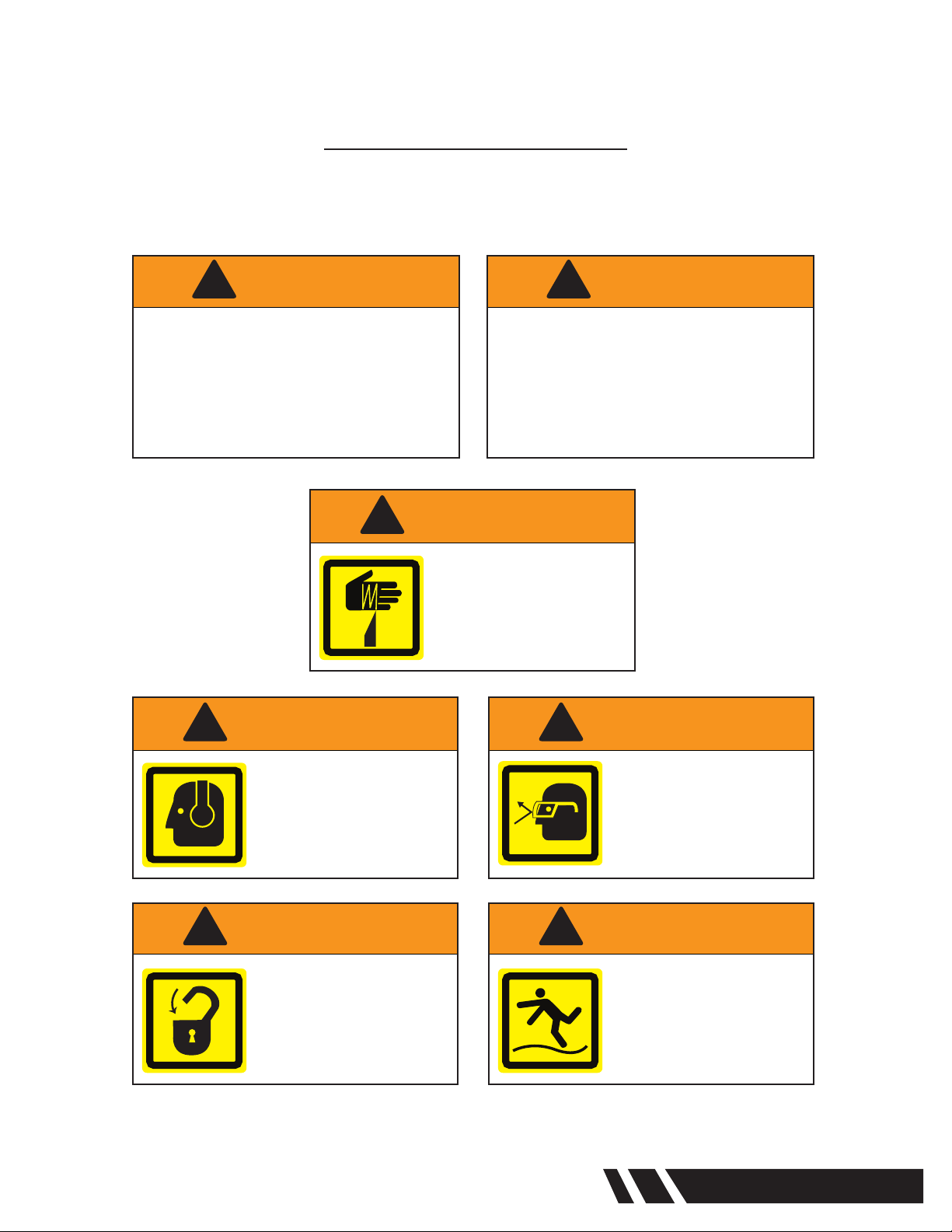
• Use appropriate safety equipment (i.e. safety glasses, ear plugs, dust masks, safety boots,
etc) when using this machine.
• Ensure that long hair or loose tting clothes are secure prior to use of the machine.
• Do Not Overreach. Keep proper footing and balance at all times.
• Never apply the machine to an unsecured work piece.
• Maintain a safe distance from the machine during use.
• Always disconnect the machine from the power source prior to performing any
maintenance or repairs.
• Keep guards in place and in good working order.
• When working on hydraulic circuits, the frame must be in the extreme down position
or mechanically blocked as the frame is always under pressure.
• Labels and Nameplates carry important information and will assist you in ordering spare
and replacement parts. If unreadable or missing, contact an Elliott service facility for a
replacement.
• Set up safety fencing around perimeter of machine to prevent unintended access
to machine, under moving frame or blade when in operation.

SpeedCut 7
Installation & Hookup
The SpeedCut was designed and manufactured to conform to high standards of performance.
For this machine to provide satisfactory service, it is necessary
that it be properly installed, operated and maintained.
This manual has been prepared to assist you in carrying out these functions. We urge you to study the
manual and follow these suggestions.
Uncrating
Carefully remove the protective crating so the saw and its parts are not marred or otherwise damaged.
Upon receipt of machine, uncrate and check all parts. In case of loss or damage, le Proof of Loss
Claim with carrier. Remove rust preventive from vertical posts using mineral spirits. Coat with light oil.
The SpeedCut has integrated forklift pockets at the back and can be moved with a forklift.
Utility Hook-Up
The use of a qualied electrician is always recommended when connecting the saw to the main power
supply. Electrical codes differ from area to area and it is the customer’s responsibility to ensure their
saw complies with applicable codes. Your SpeedCut is prewired at the factory for a specied voltage.
Check the motor and electrical panel to ensure that they are wired to correspond to your electrical
power supply. Consult the schematics for further detail.
Mounting
The SpeedCut comes with six (6) mounting holes in base. Six (6) Machine Leveling Bolts are also
included with the SpeedCut. If mounting machine to oor, use six (6) 1/2” x 4” anchoring bolts to
mount unit to concrete oor and metal shims to ensure machine is level in all directions. It is not
required to anchor the machine to the oor.
NOTE: All fasteners and bolts are SAE.

8 SpeedCut
Remote
Pedestal Bundle Support Table
Tube Sheet Support Table
Ratchet Strap
MQL Mist
Lubrication
System
Control Panel
Clamp Head Assembly
Clamp Beam
Hoist Mount Box
Blade Guides
SpeedCut Overview
Lower Frame
Anvil

SpeedCut 9
SpeedCut Overview
Limit Collars
Hoist
Baldor©Blade
Drive Motor
Blade Micro-
Switch Assembly
Control Panel
Minimum Quantity
Lubricant (MQL) System
Blade Tension Nut
Limit Switch
(rear of frame)

10 SpeedCut
See technical
drawings for more
detail.
Consult your
electrical schematic
to replace fuses.
Fuses
SCT100628-006
SCT100628-021
SCT100628-023
Drive End Roller Support
SCT102054-000
Bearings
SCT100406-002
SCT100416-003
SCT100421-002
Roller Axles
SCT101179-000
SCT101372-000
SCT101973-001
SCT102974-002
Blade Brush
SCT100133-004
Drive Belt
SCT100140-007
Gear Oil
SCT100318-030
Idle End Roller Support
SCTG-183
Electrical
Panel
Recommended Spares Kit Components

SpeedCut 11
Installation of Accessories
Bi-Metal Bandsaw Blade
See Replacing Bandsaw Blade on page 20. Also see Breaking In The Blade on page 22.
Minimum Quantity Lubricantion (MQL) System
A MQL Mist Lubrication System is a standard feature on the SpeedCut. A very thin lm of lubricant
is spread on the teeth of the blade just before the blade contacts the tube. As the heat from the cut
is absorbed by the lubricant, the liquid is dissipated from the blade and any resulting chips.
Environmental hazards and disposal costs are minimized, the cutting speed is increased,
and the blade life is prolonged.
NOTE: The MQL Lubrication System will come pre-optimized. Adjusting or changing the rate
of lubricant ow prior to initial operation may lead to dry cutting or waste of lubricant. If the lubrication
does not appear as mixed mist or spray please see the Adjustment and Repair section on page 32.
To install the MQL Mist Lubrication System:
1. Remove plug from inlet at top of MQL.
2. Remove reservoir from shipping location inside bandwheel cover.
Thread reservoir onto MQL inlet.
3. Connect (orange) oat level sensor to bottom of reservoir.
4. 90 psi air supply should be provided to machine via 1/4” air hose
near back electrical panel.
NOTE: Ensure that MQL Lubrication System is “primed” prior to initial cut.
To do this, turn COOLANT switch to ON and then press BLADE START.
Allow to run until liquid can be seen from the MQL nozzles. For added lubrication visibility,
it is recommended to add a few drops of colored food die prior to priming the system.
Bundle Support Table (optional)
Unbolt from shipping location, carefully remove the Bundle Support Table with a forklift or crane and
position in front of the SpeedCut to support the tube bundle to be cut. Included with each Bundle
Support Table is a Ratchet Strap for securing the bundle to the Bundle Support Table.
NOTE: All fasteners and bolts are SAE.

12 SpeedCut
Installation of Accessories (cont.)
Tube Sheet Support Table (optional)
If the Tube Sheet Support System is shipped separately from the
SpeedCut unit, follow steps 1-4.
If the Tube Sheet Support System is shipped with the SpeedCut,
the Tube Sheet Support Table arrives already bolted on the saw frame.
Finalize assembly according to steps 3-4.
1. Attach the Side Brackets (SCTST802) into the saw frame using
the 130GG Hex Bolts, 132H Washers, and 171G Nuts included
in the bag labeled “Tube Sheet Support Table Hardware”.
The Side Brackets should be installed so that they resemble an
upside down “L” shape with the 3/4” slots exposed at the top
for install of the table onto the brackets (Figure 1).
2. Use a forklift to place the Tube Sheet Support Table onto the
brackets with the four corner mounting holes aligned with the
3/4” slots on the side brackets (Figure 2). Make sure that the
15” X 8.5” projection at the rear of the Tube Sheet Support
Table is placed inward toward the rear of the saw frame. Using
130HL Hex Bolts,132K Washers, and 170H Nuts, secure the
corners of the table onto the brackets.
3. Place the Anvil onto the table so that the 11/16” holes are
aligned with the inner set of slots on the table. Set the Anvil
so that it will support the tube sheet at the desired cut off
distance for the bundle cut (Figure 3). Using the 130GN Hex
Bolts, 132H Washers included in the box labeled “Anvil
Hardware”, secure the Anvil by bolting through the slots in the
Tube Sheet Support Table and into the Anvil Nuts. This position
can be adjusted at any time before or after a bundle cut.
4. Secure the Eyebolts in the outer set of slots on the Tube
Sheet Support Table with the 171K Nuts, and 549-27
Washers included in the box labeled “Tube Sheet Support
Table Hardware”. Attach Shackles to the Eyebolts. The Ratchet
Strap can be utilized by attaching it to the Shackles with
the J-hooks (Figure 4).
Figure 4
Figure 1
Lower Frame
Side Bracket
Figure 2
Lower Frame
Tube Sheet Support Table
Figure 3
Lower Frame
Anvil

SpeedCut 13
Installation of Accessories (cont.)
Clamping System (optional)
1. Attach the Side Brackets (SCTST802) into the saw frame using
the 130GG Hex Bolts, 132H Washers, and 171G Nuts included
in the bag labeled “Tube Sheet Support Table Hardware”.
The Side Brackets should be installed so that they resemble an
upside down “L” shape with the 3/4” slots exposed at the top
for install of the table onto the brackets (Figure 1).
2. Use a forklift to place the Tube Sheet Support Table onto the
brackets with the four corner mounting holes aligned with the
3/4” slots on the side brackets (Figure 2). Make sure that the
15” X 8.5” projection at the rear of the Tube Sheet Support
Table is placed inward toward the rear of the saw frame. Using
130HL Hex Bolts,132K Washers, and 170H Nuts, secure the
corners of the table onto the brackets.
3. Use the “Forklift Attachments” as lift points while placing the
beam onto the center of the Tube Sheet Support Table. Align
the beam so the Hoist Mount Box is offset to the left. Position
the beam at a distance from the blade equal to typical tube
sheet cut off distances (Figure 5).
4. Bolt the beam into place onto the Tube Sheet Support
Table using (9 Each) of the 130GJ Hex Bolts and 132H
Washers (Figure 6).
5. Remove the Forklift Attachments and store these items
and hardware with the unit if future re-positioning is necessary.
NOTE: Not removing the Forklift Attachments will
prevent proper operation of the Clamp Head.
6. Place the front body of the Clamp Head Assembly
onto the Clamp Beam so the front lip is facing
downward toward the front of the saw. Now from
the rear of the clamp beam, attach the back body
of the Clamp Head Assembly using 130EG Hex Bolts
and 132G Washers included in “Clamp Head
Hardware” bag. Continued on next page...
Figure 5
Figure 1
Lower Frame
Side Bracket
Figure 2
Lower Frame
Tube Sheet Support Table
Figure 6
Beam
Tube Sheet Support Table

14 SpeedCut
Hoist Mount Box
Forklift Attachments
Clamp Head Assembly
Installation of Accessories (cont.)
Clamping System (optional) (cont.)
7. Now it is necessary to run the electrical lines from the
hoist down the rear of the clamp beam. To do this,
route the hoist pendant cord and the hoist power
cord down the rear channel created by the back
of the clamp beam and through the Clamp Head
Assembly. Utilize the SCTMC116 Cup Magnets to
secure the cords in the rear channel (Figure 7).
NOTE: Ensure both the pendant cord and the power
cord are secured in the rear channel in a way that allows
the clamp head assembly to freely slide up the clamp
beam without touching either of the cords.
8. Complete the routing of the electrical cords so the power
cord can be safely connected to the dedicated receptacle
at the rear of the saw (if available) or to a corresponding
power supply.
9. Place the pendant cord in a location that will not interfere
with the downward motion of the saw frame during a cut.
Continued on next page...
Figure 7
Hoist Pendant
Cord
Hoist Power
Cord

SpeedCut 15
Hoist Mount Box
Forklift Attachments
Clamp Head Assembly
Installation of Accessories (cont.)
Clamping System (optional) (cont.)
10. Finally with power connected to the electric hoist, use the
pendant switch to lower the hook until it touches the Eyebolt
at the top of the Clamp Head Assembly. Connect this hook
through the Eyebolt (Figure 8).
11. Ensure the hoist can safely raise the Clamp Head Assembly
without interference from the electrical cords or any other
installations.
12. Place the Anvil onto the table so that the 11/16” holes are
aligned with the inner set of slots on the table. Set the Anvil
so that it will support the tube sheet at the desired cut off
distance for the bundle cut (Figure 3). Using the 130GN
Hex Bolts, 132H Washers included in the box labeled “Anvil
Hardware”, secure the Anvil by bolting through the slots in the
Tube Sheet Support Table and into the Anvil Nuts. This position
can be adjusted at any time before or after a bundle cut.
13. Secure the Eyebolts in the outer set of slots on the Tube
Sheet Support Table with the 171K Nuts, and 549-27
Washers included in the box labeled “Tube Sheet Support
Table Hardware”. Attach Shackles to the Eyebolts. The Ratchet
Strap can be utilized by attaching it to the Shackles with
the J-hooks (Figure 4).
NOTE: All fasteners and bolts are SAE.
Figure 8
Figure 4
Figure 3
Lower Frame
Anvil

16 SpeedCut
Bundle Setup Instructions
Bundle Support Table
The Bundle Support Table should be positioned in front of the SpeedCut, with the uppermost pair of
tubes running perpendicular to the saw blade. It is important to place the tube bundle so the centerline
of the bundle is aligned with the centerline of the Bundle Support Table.
Depending on the size of the tube bundle, it may be necessary to utilize two or more Bundle Support
Tables in order to properly secure the load. If multiple tables are used, be sure to center the bundle on
each table and center all tables in the middle of the exposed saw blade.
Once the bundle has been placed onto the Bundle Support Table(s), use the included Ratchet Strap(s)
by running each Strap completely around the bundle and through the open midsection of the table.
Tighten the Strap via the ratchet to ensure the bundle remains secure.
NOTE: This is especially benecial to prevent rolling when cutting smaller bundles.
Tube Sheet Support Table
If using the Tube Sheet Support Table in conjunction with the Clamping
System, please see the Clamping System Installation Instructions.
If the table is to be used alone, the basic operations are as follows:
1. To set the cut off depth of the Anvil and the Eyebolts, loosen the
130GN Hex Bolts from the Anvil and the 171K Nuts from the
Eyebolts, slide the Anvil and Eyebolts into position (Figure 9). The
tube sheet should be centralized on the Anvil with the curved face
of the sheet having maximum contact with the Anvil. NOTE: Ensure
tube sheet is not tilted forward or backward while resting on the Anvil.
2. After the tube sheet is centralized and making maximum contact with
the Anvil, run the Ratchet Strap from one Shackle over the top of the
tube sheet to the other Shackle. Tighten down the Ratchet Strap to
secure the tube sheet.
Clamping System
1. Raise the saw frame so the saw blade is safely above the tube sheet.
2. Raise the Clamp Head with the pendant switch so the bottom of the head is even with
the raised saw blade. If necessary, move the Anvil at this time so it is straddling the base
of the Clamp Beam.
3. Position the tube bundle so the tube sheet is resting on the Anvil (without any tilting)
directly below the Clamp Head. The rest of the bundle should be supported by the
Bundle Support Table(s).
4. Once the tube sheet is in an ideal position for bundle cutting, press and hold the down
button on the pendant switch to lower the Clamp Head and release pendant switch when
full weight of Clamp Head is resting on top of tube sheet. The clamp head must be low
enough to relax all tension from hoist cable, but not create excess slack.
5. With the Clamp Head in place, attach the Ratchet Strap to one Shackle on the Tube
Sheet Support Table, run the Strap over the top face of the Clamp Head and attach to the
Shackle on the other side of the Tube Sheet Support Table. Two dowel pins are provided
as guides for feeding the Strap over the Clamp Head. Finally, tighten the Ratchet Strap
sufciently over the Clamp Head to provide additional downward pressure rmly securing
the tube sheet throughout the cut.
Figure 9

SpeedCut 17
Operating Instructions
1. Fill the MQL Lubrication System container to the 70 oz. line with the provided Advanced
Metalworking Lubricant. For additional lubricant, contact Elliott Tool Technologies.
2. For initial operation, check hydraulic oil levels and add oil as needed.
3. Set Frame Limits if necessary. See page 18 for instructions.
4. Ensure all Emergency Stops are released.
5. Raise the frame by pressing and holding the FRAME RAISE button. Release FRAME RAISE
button when frame reaches a position so the blade is above the vessel.
6. Follow Bundle Setup Instructions on page 16 to place vessel in cutting position.
NOTE: Ensure tube sheet is placed in a position that will not prohibit blade motion during cut.
7. Adjust the Blade Guides to be about one inch from the widest point of the vessel.
8. Press and hold FRAME LOWER button to lower the frame. Release button when blade is very
close, but not touching the vessel. If more rapid traverse in lowering the frame is desired, this
can be accomplished by turning the cutting speed control dial to “TRAVERSE” in a counter-
clockwise direction.
NOTE: When FRAME LOWER button is activated the yellow FEED ON light on top of the
control panel will turn on. When the frame reaches the lower feed stop limit switch, the
FRAME LOWER button is deactivated and the light will turn off.
9. With vessel in proper position for cutting and clamped, push BLADE START button
to start blade drive motor and wait for blade speed to be reached.
NOTE: Always start at a low speed.
10. Turn COOLANT switch to ON. Check to ensure adequate coolant is being applied onto blade.
11. Push FRAME LOWER button, which energizes blade micro switch and solenoid valve circuit.
The machine will then start its controlled cutting action. The frame will automatically stop
when it reaches the lower limit switch.
12. When cutting begins, notice the action of the blade micro switch located in casting
above the blade on the left blade guide assembly. This micro switch will regulate the cutting
force applied to the blade throughout the cut.
NOTE: Should the blade become stuck or jammed, the REVERSE JOG button may
be pressed to momentarily reverse the direction of blade to un-stick it. However
the REVERSE JOG button should never be pressed for more than a few seconds.
The bandwheels are pitched to keep the top of the blade against the ange while
rotating in the forward direction. Running the blade in reverse for more than ve revolutions
will cause the blade to work itself off the bandwheels.
13. Upon completion of the cut, remove the bundle from the working area.
14. Remove the tube sheet.
CAUTION
!
Ensure tube sheet has been properly secured
to avoid serious injury or damage.
Do NOT raise Clamping System until prepared
to remove the tube sheet.

18 SpeedCut
Operating Instructions (cont.)
In case of excessive feed during operation, the tension of the spring is quickly overcome. The excessive
pressure on the blade raises the stem linkage that operates the blade micro switch which closes the solenoid
valve. This stops the downward travel of the saw frame. As the cutting action of the blade removes material to
relieve this excessive pressure, the micro switch will function and open the solenoid valve for an instant until
pressure again becomes excessive. This can be noticed by the operator due to the jumpy action of the saw
frame exerting excessive pressure on the blade as the solenoid valve opens and closes.
Setting Frame Limits
It is important to adjust the frame limit collars prior to operation of the SpeedCut. The frame limit collars and
limit switch create a “safe working distance” in which the saw head will continue to travel until it reaches
either collar. The benet of this system is the ability to set an upper limit to protect structures above the
SpeedCut from interference with the rising saw head, and also to set a lower limit that will cease the saw head
motion upon completion of the cut. This gives the operator piece of mind knowing that the saw head will stop
moving once the blade has passed through the lowest section of the bundle.
To set the upper and lower frame limit collars:
1. Determine the maximum safe working height of the saw head. If there are not any restrictive
elements, ceiling, etc. above the SpeedCut it is permissible to place the collar toward the top of
the rear post.
2. Loosen the thumb screw on the upper frame limit collar and slide up the post to the maximum
desirable height. Tighten the thumb screw and the upper frame limit collar is now secured in
place.
3. Determine the minimum safe working height of the saw head. Depending on the size of the
bundle to be cut, it is typically desirable to place the lower frame limit collar approximately 1”
below the lowest tubes of the bundle to be cut. This ensures that the cut is completed and the
saw head stops slightly below the cut without bottoming out on the frame.
4. Loosen the thumb screw on the lower frame limit collar and slide down the post to the minimum
desirable height. Tighten the thumb screw and the lower frame limit collar is now secured in
place.
NOTE: Prior to initial operation it is good practice to test the frame limit switch for functionality.
To do so, make sure that the cutting area is clear and that all proper installations have been
completed. Secure the lower frame limit collar in place a few inches below the frame limit switch.
Begin the cutting motion (without actually cutting any material) by starting the blade and initiating
the downward frame feed. When the frame limit switch meets the lower frame limit collar it
will close the contacts and you will hear a click. At this time the saw head will stop feeding
downward.
NOTE: It is important to use the frame limit switch system to ensure all the solenoids are
closed and that there are no open hydraulic circuits. It is not desirable to operate this machine
by creating “hard stops”, bottoming out the saw on the lower frame upon the completion of a
bundle cut.
Establishing Correct Feed
Decrease frame feed by turning cutting speed control dial until cutting speed and feed are equalized.
Insufcient feed is easily recognized as the blade will do very little cutting, if any, due to the lack of cutting
pressure.

SpeedCut 19
Blade Instructions
When correct feed is being employed, the blade will cut steadily and the micro switch will function
occasionally to open and close the solenoid valve. The yellow FEED ON light on the top of the control box
indicates that the saw is feeding. When the solenoid valve closes, the light goes out.
After a correct feed has been established, the position of the cutting speed control dial should be noticed,
and this location maintained while cutting similar size and type material. Always keep the cutting speed
control within cutting limits, as shown on dial, during actual cutting operations.
Adjusting Spring Pressure
As the spring is compressed on the blade micro-switch assembly, more pressure must be exerted against
the blade before the micro-switch functions. The micro-switch spring controls the pressure against the blade
and considerable discretion should be used before making any change. However, it may be necessary at
times to adjust the spring pressure when radically different materials are to be cut. This adjustment can be
made by turning the knob directly mounted to the blade micro switch on the left blade guide.
Blade Speed Control
Blade Speed is indicated on the speed display on the panel. Speed is indicated in feet per minute. Control
knob is graduated in percentage from zero to 100 percent. Blade speed is adjusted with
the control knob on the front control pedestal of the machine.
Emergency Stops
During the cutting cycle, when frame is in downward travel, all operations can be stopped immediately
by pressing BLADE STOP buttons or EMERGENCY STOP button. When in upward travel, this can be
accomplished by pressing the FRAME STOP button.
Blade Speed Display
Blade Speed Adjustments
(TRAVERSE)
Control Panel
EMERGENCY STOP BUTTON

20 SpeedCut
Blade Instructions (cont.)
Replacing Bandsaw Blade
Ensure the proper protective gear is being worn (gloves, safety glasses, etc.)
when changing the blade.
1. Open the bandwheel covers and open the rear blade cover.
2. Cut old blade and remove from SpeedCut.
3. Carefully unwind the new blade with the assistance of a second person.
4. Insert new blade by lowering over the Clamping System (optional) and setting in place.
Ensure the new blade is properly aligned inside the blade guides with the blade teeth pointing
down and toward the driving bandwheel.
5. Push the blade snugly up against the ange of each bandwheel using spring clamps to
temporarily hold blade in place.
6. Slowly tighten the blade tension nut using the torque wrench provided. Continue to monitor
the blade position so that the blade remains snug against the ange of each bandwheel.
7. Continue to tighten the nut and watch the dial on the torque wrench. The blade is properly
tensioned when the torque on the nut reaches 484 kg/cm (35 lb/ft).
NOTE: Do NOT over tension. Use of a “click type” torque wrench is not recommended.
8. Remove the spring clamps, close the bandwheel covers and the rear blade cover.
Blade Guides
The blade guides are arranged to hold the blade in alignment both vertically
and horizontally. Before making adjustments, always try a new blade to be
sure that the old blade was not causing the difculty.
Blade Brushes
Brushes should be cleaned frequently in kerosene and reversed to take
advantage of both rows of bristles. For best results, replace worn, lled
or sticky brushes with new ones. In bolting brushes to angles, be sure
wire bristles are bent in the same direction as the blade travels.
Blade Break/Stall Proximity Switch
This saw is equipped with a Blade Break/Stall Proximity Switch. Should the
blade break or stall in the work, the blade motor will stop if the saw ceases
operation. This allows the operator to leave the machine unattended with
greater condence. The operation of this feature is fully automatic and
requires no attention. The sensor is located under the Idle Bandwheel
and monitors the spokes as they pass over the sensor.
Saw Frame Rests/Stops
At the bottom of the stroke the saw frame rests on two removable stops.
Should the saw frame need to be lowered below the base position, these
stops can be temporarily removed.
Belt
Proper adjustment of the ‘V’ belt is important to prevent overheating
of the motor. Be sure the belt guard is closed after changing blade speeds.
Blade Break/Stall Proximity Switch
Blade Guides
This manual suits for next models
1
Table of contents
Other Elliott Cutter manuals
Popular Cutter manuals by other brands

Martin Yale
Martin Yale Martin Yale 3800 AP Installation, maintenance & operating instructions

Panther
Panther DUALBLADEROOFCUTTER instruction manual

DeWalt
DeWalt DCE555D2 instruction manual

Omcan
Omcan FP-IT-0004-VT instruction manual

Sealey
Sealey GSA25.V2 instructions

Amazon
Amazon B073J92G1J quick start guide