ELMEKO MSE 20 User manual

2
INHALTSVERZEICHNIS TABLE OF CONTENTS
Anwendung....................................................................................................................................................................... 3
Technische Daten...............................................................................................................................................................3
Beschreibung......................................................................................................................................................................4
Berechnungssoftware DELTA T ..........................................................................................................................................4
Lieferumfang .………………….................................................................................................................................................5
Zubehör..............................................................................................................................................................................5
Montage.............................................................................................................................................................................5
Montageablauf...................................................................................................................................................................6
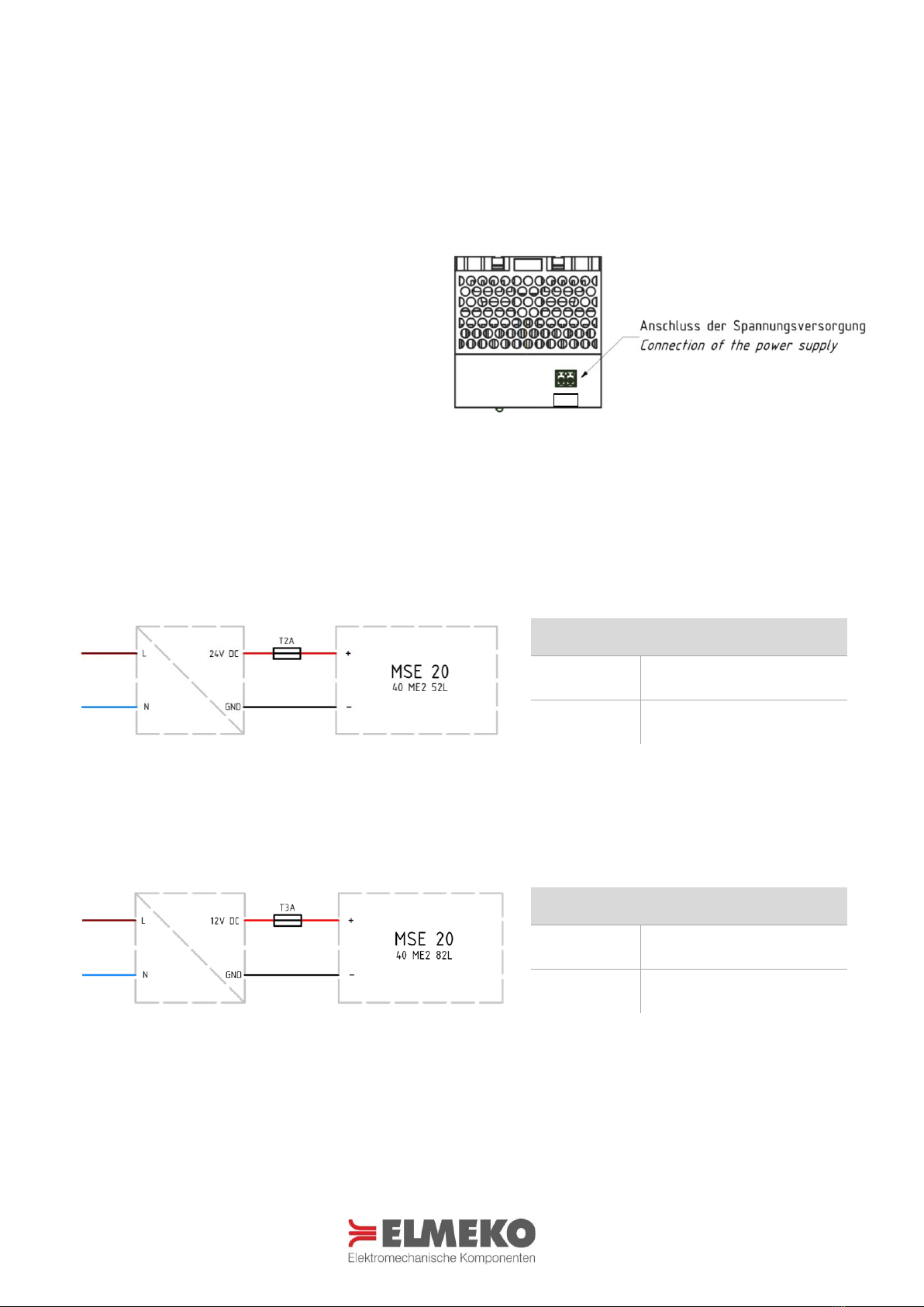
Elektrischer Anschluss........................................................................................................................................................7
Schaltbilder ........................................................................................................................................................................7
Funktionsbeschreibung......................................................................................................................................................8
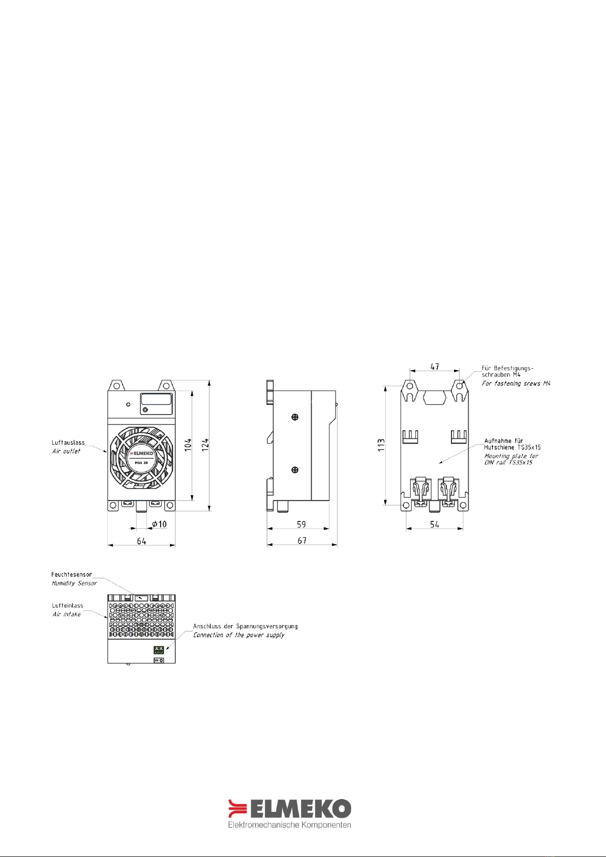
Abmessungen.....................................................................................................................................................................8
Sicherheitshinweise ...........................................................................................................................................................9
Wartung und Pflege ...........................................................................................................................................................9
Garantieerklärung ............................................................................................................................................................10
Application........................................................................................................................................................................ 3
Technical data ....................................................................................................................................................................3
Description.........................................................................................................................................................................4
Calculation Software DELTA T............................................................................................................................................4
Delivery contents………………...............................................................................................................................................5
Accessories.........................................................................................................................................................................5
Installation .........................................................................................................................................................................5
Assembly procedure ..........................................................................................................................................................6
Electric installation.............................................................................................................................................................7
Wiring diagrams .................................................................................................................................................................7
Functional description........................................................................................................................................................8
Dimensions.........................................................................................................................................................................8
Safety instructions..............................................................................................................................................................9
Care and maintenance .......................................................................................................................................................9
Guarantee bond ...............................................................................................................................................................10
*Abbildung auf der Titelseite zeigt Entfeuchtungsgerät von der Vorder- und Rückseite
Illustration on the title page shows Dehumidifier in front and rear view

3
ANWENDUNG APPLICATION
Feuchtigkeit in Schaltschränken ist ein großes Problem und wird oft unterschätzt. Bei Temperaturschwankungen kommt es
zu Kondensation und das verursacht Korrosion, Störungen und Ausfall von Steuerungen. Schon ein Tropfen Wasser an der
falschen Stelle kann erhebliche Folgen haben. Deshalb werden Entfeuchtungsgeräte überall eingesetzt, wo durch Feuchte
oder Temperaturschwankungen Kondensation auftritt. Das ist fast generell bei Outdooranwendungen der Fall,
insbesondere bei tropischem Klima und in verschiedenen Branchen, wie z.B. der Lebensmittelindustrie.
Moisture in switchgear cabinets is a serious problem - and one that is often underestimated. Fluctuations in temperature
lead to condensation, which in turn causes corrosion, electrical faults and control unit failure. Just one water droplet in the
wrong place can have far-reaching consequences. Therefore, Dehumidifiers are installed wherever moisture or
fluctuations in temperature cause condensation. This is generally the case in almost all outdoor applications –particularly
in tropical climates –and in various specific industries e.g. the food and beverage industry.
TECHNISCHE DATEN TECHNICAL DATA
Bezeichnung Type
MSE 20 –24 V DC
MSE 20 –12 V DC
Artikelnummer Part number
40 ME2 52L
40 ME2 82L
Betriebsspannung
Operating voltage
24 V DC
12 V DC
Eingangs-Spannungsbereich
Input voltage range
20 - 26 V DC
10 - 14 V DC
Stromaufnahme
Amperage
1,0 A
1,7 A
Anlaufstrom
Starting current
1,2 A
2,0 A
Nennleistung
Nominal power
30 W
24 W
Vorsicherung
Fuse
2 A (T)
3 A (T)
Entfeuchtungsleistung
Dehumidifying capacity
250 ml / 24 h (35 °C, 85 % RH)
200 ml / 24 h (35 °C, 85 % RH)
Messbereich der Luftfeuchtigkeit
Humidity detection range
1% r.F … 99 % RH
Messgenauigkeit
Measurement accuracy
±3 % RH
Entfeuchtungsautomatik Start- / Stoppwert
Automatic dehumidificatio start / stop value
55 % RH/ 35 % RH
Luftvolumenstrom
Air volume flow
19,2 m³/h
Schalldruck
Sound pressure
37 dB(A) @1m
Schutzart
Degree of protection
IP20
Lebensdauer
Service life
50.000 h
Gewicht
Weight
320 gr.
Einsatztemperatur
Operating temperature
-10 °C … +55 °C
Lagertemperatur
Storage temperature
-30 °C … +70 °C
Zulassung
Approval
CE / UKCA

4
BESCHREIBUNG DESCRIPTION
Bezeichnung Type
Beschreibung Description
MSE 20 –24 V
Schaltschrankentfeuchter mit integrierter Feuchteregelung für die Hutschienenmontage, 24 V DC
Enclosure dehumidifier with integrated humidity controller for DIN rail mounting, 24 V DC
MSE 20 –12 V
Schaltschrankentfeuchter mit integrierter Feuchteregelung für die Hutschienenmontage, 12 V DC
Enclosure dehumidifier with integrated humidity controller for DIN rail mounting, 12 V DC
EIGENSCHAFTEN FEATURES
▪Integrierte Luftfeuchtigkeitsregelung
▪Einfacher Anschluss und Bedienung
▪Geringer Stromverbrauch
▪Montage auf Hutschiene
▪Hohe Entfeuchtungsleistung
▪Platzsparend
▪Geringes Gewicht
▪Übertemperaturschutz
▪Automatische Abtaufunktion
▪Integrated humidity controller
▪Quick and easy setup
▪Low power consumption
▪Easy mounting on DIN rail
▪High dehumidifying performance
▪Compact, small dimensions
▪Light wight
▪Overtemperature protection
▪Automatic defrosting at low temperature
BERECHNUNGSSOFTWARE DELTA T CALCULATION SOFTWARE DELTA T
Mit unserem Berechnungsprogramm DELTA T haben Sie die Möglichkeit die benötigte Kühlleistung für Ihr Projekt genau zu
ermitteln. Für ein präzises Ergebnis werden alle relevanten Einflussfaktoren wie z.B. Schaltschrankgröße
und -material, Temperaturen, Verlustleistung, und Aufstellungsart in der Software berücksichtigt.
With our calculation tool DELTA T you have the possibility to determine the required cooling capacity for your project.
For a precise result, all relevant influences such as cabinet size and material, temperatures, heat dissipation and
installation type are considered in the software.
Mit dem QR-Code oder per Klick auf den untenstehenden
Link haben Sie direkten Zugang zur Webversion der
Berechnungssoftware DELTA T.
Das Berechnungstool ist auch als kostenlose App im
Apple App Store und Google Play Store verfügbar.
With the QR code or by clicking on the link below you
have direct access to the web version of the calculation
software Delta T.
The calculation tool is also available as free app in the
www.elmeko.de/deltaT/

5
LIEFERUMFANG DELIVERY CONTENTS
▪Schaltschrankentfeuchter
▪Kurzanleitung
▪Steckbare Anschlussklemme
▪1m Silkonschlauch
▪Dehumidifier
▪Quick reference guide
▪Pluggable terminal block
▪1m silicon rubber hose
ZUBEHÖR ACCESSORIES
Bezeichnung Type
Beschreibung Description
Artikelnummer Part number
Emparro 5
Netzteil Emparro 5
Power supply Emparro 5
42 05A 500
OF-M20-BA
Die All-in-One Lösung für Druckausgleich und
Entwässerung aus der OUT-FIT Serie
The all-in-one solution for pressure equalization
and drainage from the OUT-FIT series
74 OF20 BA
MONTAGE INSTALLATION
Das Gerät kann auf einer Tragschiene TS 35 × 15 mm oder alternativ mit Schrauben M4 durch die im Gerät vorgesehenen
Bohrungen befestigt werden. Die horizontale Einbauposition mit dem Schlauchanschluss nach unten ist unbedingt
einzuhalten. Der Kondensatschlauch wird an der Unterseite des Gerätes auf den Schlauchanschluss aufgeschoben und
muss in einen Behälter unterhalb des Gerätes oder durch die Schaltschrankwand nach außen geführt werden.
Optimalerweise wird dafür ein OUT-FIT Element aus dem Zubehör verwendet.
Es ist ein Abstand zu benachbarten Geräten von mindestens 80 mm nach oben und vorne einzuhalten, damit der
Lufteinlass (Geräteoberseite) und der Luftauslass (Vorderseite) nicht beeinträchtigt werden.
The unit can be installed on a TS 35 × 15 mm mounting rail or, alternatively, with M4 screws through the holes provided in
the unit. The horizontal installation position with the hose connection pointing downwards must be observed. Push the
condensate hose onto the hose connection on the underside of the device and led it into a container underneath the
device or through the enclosure wall. Ideally, an OUT-FIT element from the accessories is used for this.
A distance of at least 80 mm to the top and front of neighboring devices must be maintained so that the air inlet (top of
the dehumidifier) and air outlet (front) are not impaired.
Weitere Lösungen für Kondensatableitung und Druckausgleich, finden Sie im Bereich Schaltschrank Zubehör auf unserer Website.
Further solutions for condensate drainage and pressure equalization can be found in the section Accessories on our website.

6
MONTAGEABLAUF
ASSEMBLY PROCEDURE
Alternative Befestigung mit Schrauben Alternative fastening with screws
①
②
③
Befestigung mit 4 Schrauben M4 × 12 mm
und Unterlegscheiben.
Max. Anzugsdrehmoment: 2 Nm.
Die Schrauben sind nicht im Lieferumfang
enthalten.
Fastening with 4 screws M4 × 12 mm and
washers.
Max. Tightening torque: 2 Nm.
The screws are not included in the scope
of delivery.

7
ELEKTRISCHER ANSCHLUSS ELECTRIC INSTALLATION
Für den elektrischen Anschluss ist der Schaltschrank vorher vorschriftsmäßig außer Betrieb zu nehmen. Es wird je nach
Geräteausführung eine Gleichspannung von 24 V DC (Art.-Nr. 40 ME2 52L) oder 12 V DC (Art.-Nr. 40 ME2 82L) benötigt.
ACHTUNG: Bei Anschluss an eine Wechselspannung wird das Gerät zerstört.
Die Spannungsversorgung wird mittels der beiliegenden steckbaren Anschlussklemme mit dem Geräteanschluss
verbunden. Dabei ist auf die richtige Polarität entsprechend den auf der Geräteoberseite eingeprägten Symbolen (+/-) zu
achten.
For the electrical connection, the control cabinet must
first be disconnected. Depending on the device version,
a power supply of 24 V DC (part no. 40 ME2 52L) or 12 V
DC (part no. 40 ME2 82L) is required.
ATTENTION: AC current will destroy the cooler. Connect
the supply voltage via the enclosed plug-in terminal to
the device. Make sure that the polarity is correct
according to the symbols embossed on the top of the
unit (+/-).
SCHALTBILDER WIRING DIAGRAMS
Schaltbild MSE 20 - 24V Wiring diagram MSE 20 - 24V
Schaltbild MSE 20 - 12V Wiring diagram MSE 20 - 12V
Bezeichnung
Term
Belegung Connection
+
24 V DC (40 ME2 52L)
–
0V DC
Bezeichnung
Term
Belegung Connection
+
12 V DC (40 ME2 82L)
–
0V DC
Ansicht von oben Top view
Netzteil separat erhältlich
Power supply optionally available
Netzteil separat erhältlich
Power supply optionally available
–+

8
FUNKTIONSBESCHREIBUNG FUNCTIONAL DESCRIPTION
Ist das Entfeuchtungsgerät im Schaltschrank montiert und die Versorgungsspannung angeschlossen, arbeitet das Gerät
vollautomatisch. Sobald die grüne LED am Gerät aufleuchtet, misst ein Sensor permanent die aktuelle Luftfeuchtigkeit im
Gehäuse und startet den Entfeuchtungsprozess, wenn die Luftfeuchte mehr als 55 % r.F. beträgt. Die Entfeuchtung wird
beendet, sobald die Luftfeuchtigkeit einen Wert unter 35 % r.F. erreicht hat und das Gerät geht in den
Bereitschaftsmodus.
Sinkt die Schaltschranktemperatur unterhalb von 9 °C, wird der Frostschutzmodus aktiviert. Das Entfeuchtungsgerät geht
in einen Intervallbetrieb, in dem sich 180 Sekunden Entfeuchtung mit 150 Sekunden Pause abwechseln. Steigt die
Temperatur wieder auf über 11 °C, wird der Frostschutzmodus gestoppt.
Zum Schutz vor Überhitzung, stellt das Entfeuchtungsgerät den Betrieb oberhalb von 55 °C ein.
If the dehumidifier is mounted in the control cabinet and connected to the power supply, the device operates fully
automatically. When the green LED on the device lights up, a sensor permanently measures the current humidity in the
housing and starts the dehumidification if the humidity is higher than 55 % RH. Dehumidification stops as soon as the
humidity reaches a value below 35 % RH and the device goes into standby mode.
If the control cabinet temperature drops below 9 °C, the frost protection mode is activated. The dehumidifier goes into
interval operation with alternating 180 seconds of dehumidification followed by a 150 second pause. If the temperature
rises above 11 °C again, the frost protection mode is stopped.
To protect against overheating, the dehumidifier stops operating above 55 °C.
ABMESSUNGEN DIMENSIONS
Alle Maße in mm All dimensions in mm

9
SICHERHEITSHINWEISE SAFETY INSTRUCTIONS
▪Die Installation darf nur von autorisiertem Fachpersonal vorgenommen werden. Die landesüblichen
Richtlinien sind gemäß IEC 60364 einzuhalten
▪Die technischen Daten auf dem Typenschild und in dieser Anleitung sind zu beachten
▪Der Anschluss erfolgt je nach Gerätevariante an 24 V DC oder 12 V DC
▪Anschlusskabel sind nur als Kupferleitungen zulässig
▪Die maximale Umgebungstemperatur von bis zu 55 °C ist zu berücksichtigen
▪Die Umgebung des Geräts darf max. Verschmutzungsgrad 2 entsprechen
▪Vorschriften des EVU sind zu beachten
▪Bei Beschädigung des Gehäuses oder der Anschlussleitung Spannung abschalten und alle Stecker abziehen
▪Achtung! Beim Öffnen des Gerätes erlischt die Garantie
▪Schutzmaßnahmen nach VDE 0100 sind sicherzustellen
▪Bei der Herstellung von Montageausschnitten und Bohrungen ist geeignete Schutzausrüstung zu tragen
▪Luftein- und Luftaustrittsöffnungen des Gerätes dürfen nicht abgedeckt werden
▪Stellen Sie vor der Montage sicher, dass der Schaltschrank hermetisch dicht versiegelt ist, ansonsten tritt später
während des Betriebs eine erhöhte Kondensatbildung auf
▪Installation must only be carried out by qualified electrical technicians in observation of the respective national power
supply guidelines (IEC 60364)
▪The technical specifications on the identification plate and in this manual, must be observed
▪Supply voltage is 24 V DC or 12 V DC, depending on the device variant
▪Connection cables only as copper conductors only
▪Taking into account the maximum surrounding air temperature rating of 55 °C
▪The environment of the device may be maximum with pollution degree 2
▪If the housing, or wire is damaged, switch off the voltage supply and disconnect all plugs
▪Attention! Opening the case will void guarantee
▪The safety measures according to VDE 0100 have to be ensured
▪Wear protective gear when cutting the mounting cut out and drilling the fastening holes
▪The air inlet and outlet openings to the unit must not be covered
▪Before mounting, make sure that the enclosure is hermetically sealed, otherwise increased condensation will occur later
during operation
WARTUNG UND PFLEGE CARE AND MAINTENANCE
▪Das Entfeuchtungsgerät ist wartungsarm.
▪Führen Sie in regelmäßigen Abständen eine Sichtprüfung an dem Lüfter durch.
▪The dehumidifier is low-maintenance
▪Regularly perform a visual inspection at the fan
Die Entsorgung muss gemäß den jeweiligen nationalen gesetzlichen Bestimmungen erfolgen.
The disposal is to occur according to the respective national regulations.
WEEE-Reg.-Nr.: DE 78723147

10
GARANTIEERKLÄRUNG GUARANTEE BOND
Wir gewähren eine Garantiezeit von 24 Monaten
▪ab dem Zeitpunkt der Lieferung des Gerätes bei bestimmungsgemäßem Einsatz und unter den folgenden
Betriebsbedingungen:
▪Einsatz in Schaltschränken oder Gehäusen für industrielle Anwendungen.
▪Beachtung der auf dem Typenschild angegebenen Anschlussspannung und Anschlussleistung.
Diese Garantie gilt nicht für Schäden, die dem Gerät zugefügt werden durch:
▪Inbetriebnahme in ungeeigneter Umgebung, z. B. in saurer oder ätzender Atmosphäre.
▪Anschluss an eine andere Spannung, wie auf dem Typenschild angegeben.
▪Überspannung, z. B. Blitzeinschlag.
▪Äußere Gewaltanwendung.
Die Garantie entfällt bei Nichtbeachten der Vorschriften in der Betriebsanleitung
▪Die richtige Erdung, Installation und Stromversorgung des Gerätes entsprechend den gültigen Vorschriften obliegen dem
Kunden, der dafür die alleinige Haftung trägt.
Im Schadensfall innerhalb der Garantiezeit, übernimmt der Hersteller eine Materialgarantie
▪Der Besteller zeigt den Schaden des Gerätes an und erhält für die defekten Teile Ersatz.
▪Der Hersteller übernimmt keine Kosten für Ein- und Ausbau der defekten Teile, des Gerätes oder der Folgeschäden.
▪Die reparierten oder ausgetauschten Bauteile verändern nicht den Beginn oder die Beendigung der Garantiezeit.
Achtung:
▪Alle Eingriffe in das Gerät haben den Verfall der Gewährleistung und den Haftungsausschluss zur Folge!
We grant a warranty period of 24 months. This applies:
▪From the moment of delivery of the device.
▪When used as intended, considering the information in the respective operating instructions.
▪Use in control cabinets or housings for industrial applications.
▪Observance of the connection voltage and connection power specified on the rating plate.
This warranty does not apply to damage caused to the device by:
▪Commissioning in an unsuitable environment, e.g., in an acidic or corrosive atmosphere.
▪Connection to a different voltage as indicated on the rating plate.
▪Overvoltage, e.g., lightning strike.
▪External use of force.
The warranty does not apply if the instructions in the operating manual are not observed
▪The correct grounding, installation and power supply of the device in accordance with the applicable regulations are the
responsibility of the customer, who bears sole liability for this.
In the case of damage within the warranty period, the manufacturer assumes a material warranty
▪The customer reports the damage to the device and receive a device in exchange or replacement for the defective part.
▪The manufacturer does not assume any costs for installation and removal of the defective parts, the device or the
consequential damages.
▪The repaired or replaced parts do not change the beginning or end of the warranty period.
Attention:
▪Any tampering with the device will void the warranty and exclude liability!
Rev. 12/2022
ELMEKO GmbH + Co. KG Graf-Zeppelin-Str. 5 56479 Liebenscheid Germany
Other manuals for MSE 20
1
This manual suits for next models
2
Table of contents
Other ELMEKO Dehumidifier manuals
Popular Dehumidifier manuals by other brands

Electrolux
Electrolux EXD15DN3W user manual

Mitsubishi Electric
Mitsubishi Electric MJ-E14CG-S1-SWE instruction manual

COLUMBIA VAC
COLUMBIA VAC desi OP600 instruction manual

CTM International
CTM International DLW120 Operations & installation guide

Damp2Dry
Damp2Dry PACD150 user manual

ROWAN ELECTRIC APPLIANCE
ROWAN ELECTRIC APPLIANCE OL12D-D023B instruction manual