ELNA eXperience 660 User manual

SERVICE MANUAL
eXperience 660

CONTENTS
WHAT TO DO WHEN................................................................................ 1 - 3
SERVICE ACCESS ................................................................................... 4 - 9
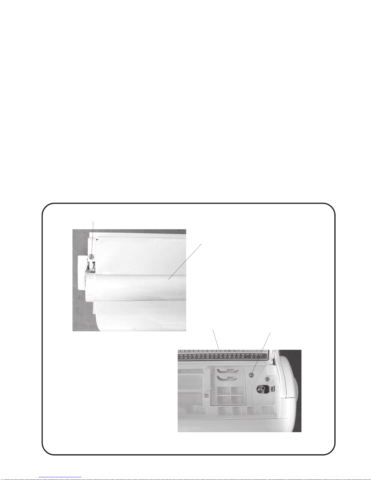
FACE COVER ........................................................................................ 4
TOP COVER .......................................................................................... 5
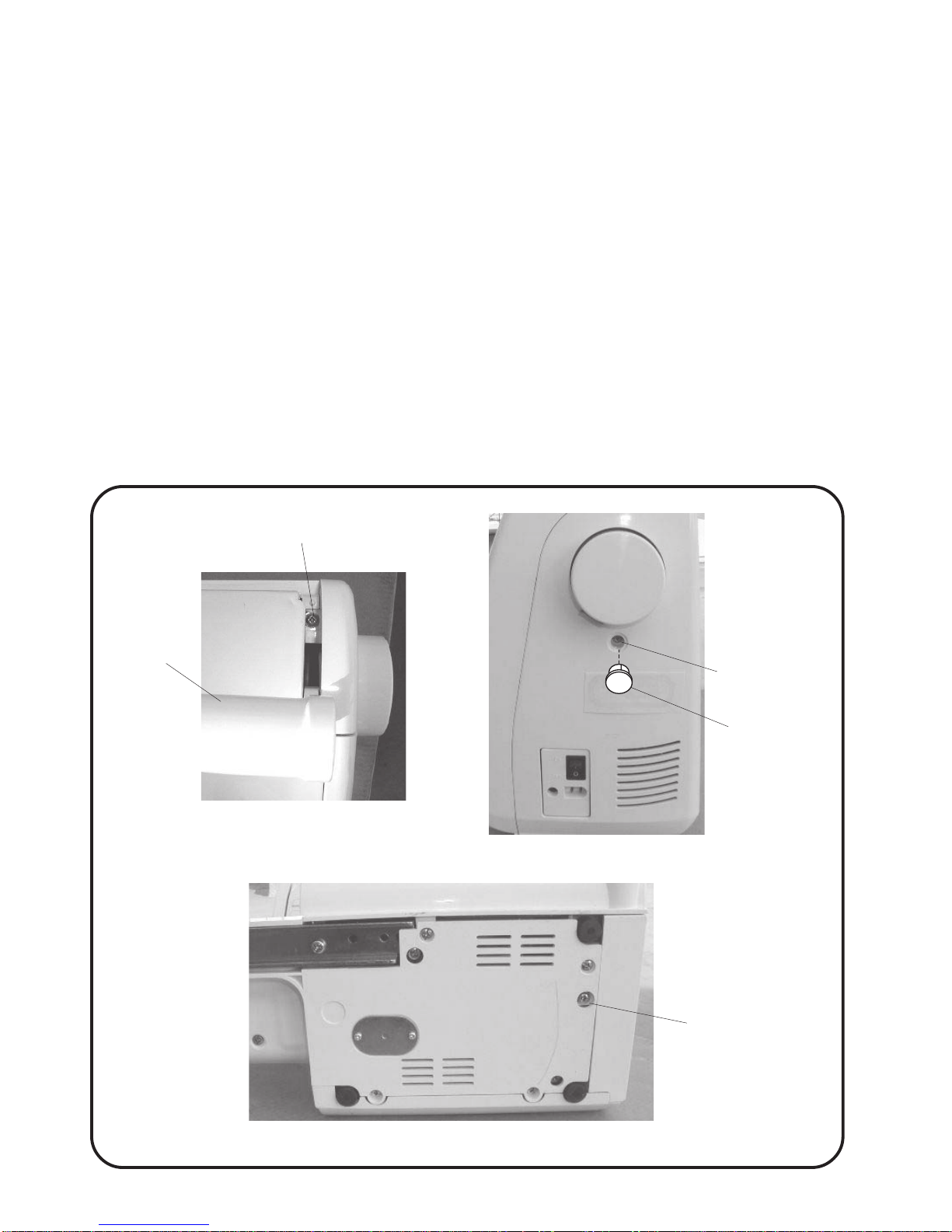
BELT COVER ........................................................................................ 6
BED COVER .......................................................................................... 7
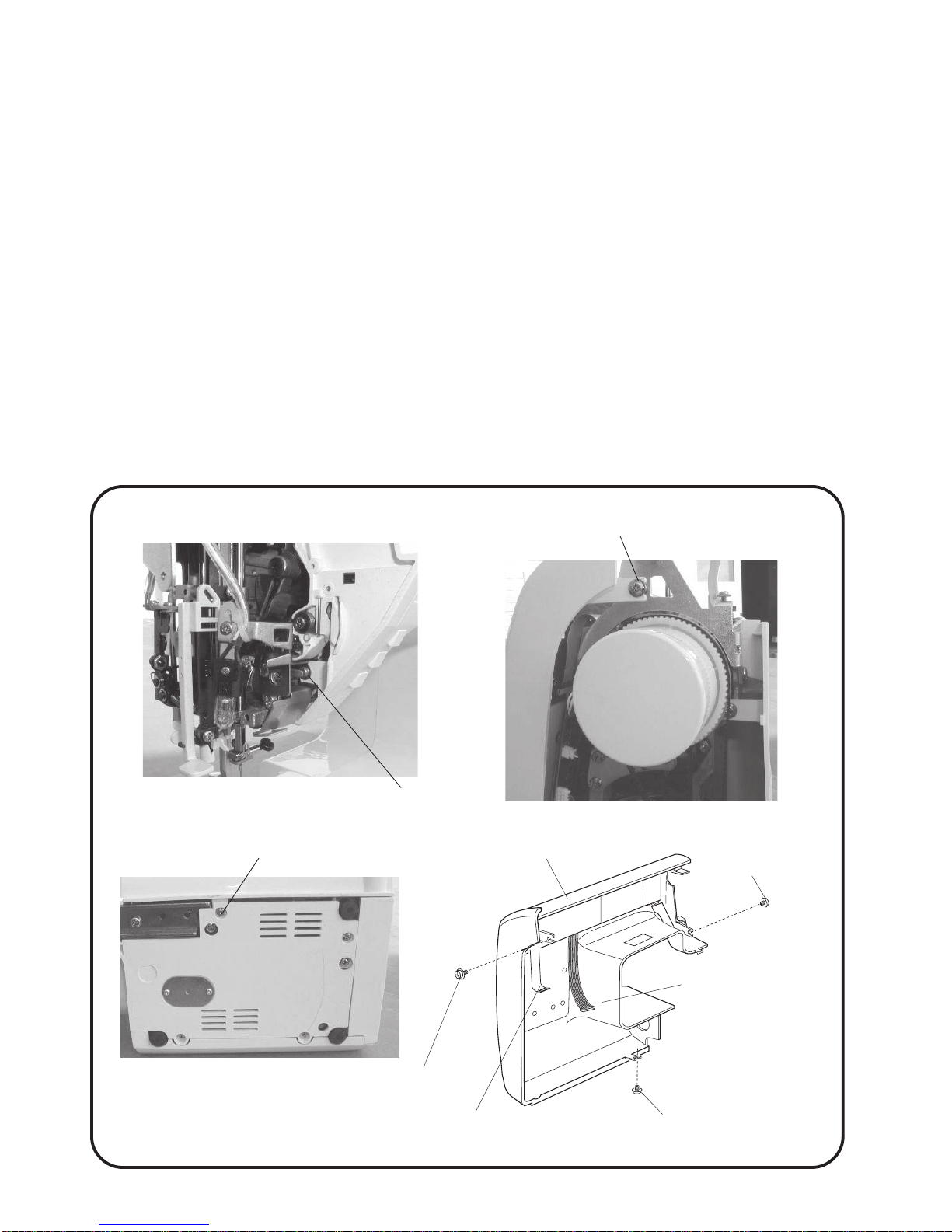
FRONT COVER ..................................................................................... 8
REAR COVER ....................................................................................... 9
ADJUSTING PRESSER FOOT HEIGHT AND ALIGNMENT ...................... 10
NEEDLE DROP POSITION ALIGNMENT ....................................................11
ADJUSTING HOOK TIMING ....................................................................... 12
ADJUSTING NEEDLE BAR HEIGHT .......................................................... 13
ADJUSTING CLEARANCE BETWEEN NEEDLE AND HOOK .................. 14
ADJUSTING BACKLASH BETWEEN HOOK DRIVE GEAR
AND LOWER SHAFT GEAR .............................................................. 15
FEED DOG HEIGHT ADJUSTMENT ........................................................... 16
ZIGZAG SYNCHRONIZATION .................................................................... 17
NEEDLE THREAD TENSION ...................................................................... 18
STRETCH STITCH FEED BALANCE ......................................................... 19
REPLACEMENT AND ADJUSTMENT
OF THE NEEDLE THREADER PLATE............................................... 20
CONNECTOR DIAGRAM ............................................................................ 21
SELF DIAGNOSTIC TEST.................................................................... 22 - 25
REPLACING PRINTED CIRCUIT BOARD “A” .......................................... 26
REPLACING PRINTED CIRCUIT BOARD “K” AND “F” ........................... 27
REPLACING DC MOTOR
AND ADJUSTING MOTOR BELT TENSION ...................................... 28
REPLACING THE FUSES ........................................................................... 29
REPLACING MACHINE SOCKET (UNIT) ................................................... 30
REPLACING THE TRANSFORMER ........................................................... 31
REPLACING THE ZIGZAG WIDTH MOTOR .............................................. 32
REPLACING FEED STEPPING MOTOR .................................................... 33
ADJUSTING BUTTONHOLE LEVER POSITION........................................ 34
ADJUSTING THE BOBBIN WINDING SWITCH ......................................... 35
ADJUSTING KNEE LIFTER HEIGHT.......................................................... 36
OILING ......................................................................................................... 37

1
MODEL:eXperience 660
CONDITION CAUSE HOW TO FIX REFERENCE
1. SKIPPING
STITCHES
1. NEEDLE IS NOT INSERTED
PROPERLY.
2. NEEDLE IS BENT OR WORN.
3. INCORRECTLY THREADED.
4. NEEDLE OR THREAD ARE
INAPPROPRIATE FOR
FABRIC BEING SEWN.
5. SEWING ON STRETCH
FABRIC.
6. PRESSER FOOT PRESSURE
IS TOO WEAK.
7. INAPPROPRIATE NEEDLE
BAR HEIGHT.
8. INAPPROPRIATE NEEDLE
TO SHUTTLE TIMING.
9. INAPPROPRIATE NEEDLE
TO SHUTTLE CLEARANCE.
INSERT THE NEEDLE PROPERLY.
CHANGE THE NEEDLE.
RETHREAD.
USE THE RECOMMENDED
SEWING NEEDLE AND THREAD.
USE A #11 BLUE TIP NEEDLE.
ADJUST THE PRESSER BAR
LEVEL TO MAKE THE
PRESSURE STRONGER.
SEE MECHANICAL ADJUSTMENT
“NEEDLE BAR HEIGHT”.
SEE MECHANICAL ADJUSTMENT
“NEEDLE TO SHUTTLE TIMING”.
SEE MECHANICAL ADJUSTMENT
“CLEARANCE BETWEEN NEEDLE
AND HOOK”.
P. 1 3
P. 1 2
P. 1 4
2. FABRIC NOT
MOVING
1. PRESSER FOOT PRESSURE
IS TOO WEAK.
2. INCORRECT F.D. HEIGHT.
3.F.D. IS IN DOWN POSITION.
4.THREAD ON BOTTOM SIDE
OF FABRIC IS JAMMED UP.
5. FEED DOG TEETH ARE WORN.
ADJUST THE PRESSER BAR
LEVEL TO MAKE THE
PRESSURE STRONGER.
SEE MECHANICAL
ADJUSTMENT “FEED DOG HEIGHT”.
RAISE THE F.D. LEVEL.
MAKE SURE TO BRING BOTH
NEEDLE AND BOBBIN.
THREAD UNDER THE FOOT WHEN
STARTING SEWING.
CHANGE THE FEED DOG.
P. 1 6
WHAT TO DO WHEN

2
MODEL:eXperience 660
CONDITION CAUSE HOW TO FIX REFERENCE
3. BREAKING
UPPER
THREAD
1. INITIAL SEWING SPEED IS
TOO FAST.
2. THREAD PATH IS INCORRECT.
3. NEEDLE IS BENT OR DULL.
4. UPPER THREAD TENSION IS
TOO STRONG.
5. NEEDLE SIZE IS
INAPPROPRIATE FOR FABRIC.
6. NEEDLE EYE IS WORN.
7. NEEDLE HOLE IN NEEDLE
PLATE IS WORN OR BURRED.
START WITH MEDIUM SPEED.
USE THE PROPER THREAD PATH.
REPLACE WITH A NEW NEEDLE.
ADJUST NEEDLE THREAD TENSION
CORRECTLY.
USE APPROPRIATE NEEDLE FOR
FABRIC AND THREAD IN USE.
CHANGE THE NEEDLE.
REPAIR THE HOLE OR REPLACE
THE NEEDLE PLATE.
P. 1 8
4. BREAKING
BOBBIN
THREAD
1. INCORRECTLY THREADED
BOBBIN.
2. TOO MUCH THREAD IS
AROUND ON THE BOBBIN.
3. LINT IS STUCK INSIDE THE
BOBBIN HOLDER.
4. THREAD QUALITY IS
TOO LOW.
5. THREAD IS JAMMING
AROUND THE BOBBIN.
THREAD BOBBIN CORRECTLY.
ADJUST THE POSITION OF STOPPER.
CLEAN THE SHUTTLE.
CHANGE TO A HIGH QUALITY
SEWING THREAD.
CLEAR OUT THE JAMMING THREAD.
5. NEEDLE
BREAKS
1. NEEDLE IS HITTING THE
NEEDLE PLATE.
2. NEEDLE IS BENT OR WORN.
3. NEEDLE IS HITTING THE
SHUTTLE.
4. THE FABRIC MOVES WHILE
THE NEEDLE IS PIERCING
IT, OR THE NEEDLE ZIGZAGS
WHILE IN FABRIC.
5. FABRIC IS BEING PULLED TOO
STRONGLY WHILE SEWING.
SEE MECHANICAL
ADJUSTMENT “NEEDLE POSITION”.
CHANGE THE NEEDLE.
SEE MECHANICAL ADJUSTMENT
“CLEARANCE BETWEEN NEEDLE
AND HOOK”.
SEE MECHANICAL ADJUSTMENT
“ZIGZAG SYNCHRONIZATION”.
GUIDE THE FABRIC GENTLY
WHILE SEWING.
P. 11
P. 1 4
P. 1 7

3
MODEL:eXperience 660
CONDITION CAUSE HOW TO FIX REFERENCE
6. NOISY
OPERATION
1. BACKLASH BETWEEN SHUTTLE
HOOK GEAR AND LOWER
SHAFT GEAR IS TOO GREAT.
2. LOWER SHAFT GEAR IS
LOOSE.
3. INAPPROPRIATE BELT
TENSION.
4. NOT ENOUGH OIL.
SEE MECHANICAL ADJUSTMENT
“BACKLASH (LOWER SHAFT GEAR)”.
ELIMINATE THE LOOSENESS.
SEE PART REMOVAL AND
REPLACEMENT “DRIVING MOTOR
(DC MOTOR)”.
OIL ALL MOVING PARTS.
P. 1 5
P. 2 8
P. 3 7
7. DEFORMATION
PATTERN
1. INAPPROPRIATE FEED
BALANCE.
2. INAPPROPRIATE ZIGZAG
SYNCHRONIZATION.
3. UPPER THREAD TENSION
IS TOO STRONG.
SEE MECHANICAL ADJUSTMENT
“STRETCH STITCH FEED BALANCE”.
SEE MECHANICAL ADJUSTMENT
“ZIGZAG SYNCHRONIZATION”.
SEE MECHANICAL ADJUSTMENT
“NEEDLE THREAD TENSION”.
P. 1 9
P. 1 7
P. 1 8

4
MODEL:eXperience 660
Setscrew
Cap
Face cover
SERVICE ACCESS (1)
FACE COVER (UNIT)
TO REMOVE:
Remove the cap and setscrew.
Remove the face cover
TO ATTACH:
Follow the procedure above in reverse.

5
MODEL:eXperience 660
SERVICE ACCESS (2)
TOP COVER (UNIT)
TO REMOVE:
Raise the carrying handle and the setscrew (A).
Open the top cover and remove the setscrew (B).
Lift up the top cover and remove it from the rear side.
TO ATTACH:
Follow the procedure above in reverse.
Setscrew (A)
Carrying handle
Setscrew (B)
Face plate

6
MODEL:eXperience 660
Setscrew (A)
Carrying
handle Setscrew (B)
Setscrew (C)
Cap
SERVICE ACCESS (3)
REPLACING THE BELT COVER
TO REMOVE:
Raise the carrying handle and loosen the screw (A).
Remove the cap and the screw (B).
Loosen the screw (C) and the belt cover.
TO ATTACH:
Follow the procedure in reverse.

7
MODEL:eXperience 660
Setscrew (B)
Setscrews (A)
Drop feed dog lever
Bed cover (unit)
Setscrew (C)
Setscrew (A)
Setscrew (D)
Setscrew (E)
Base
SERVICE ACCESS (4)
REPLACING THE BED COVER (UNIT)
TO REMOVE:
Push the drop feed dog lever to the left. Remove the setscrews (A), then remove the bed cover (unit).
TO ATTACH:
Push the drop feed dog lever to the left. Attach the bed cover (unit) and tighten the setscrews (A).
REPLACING THE BASE
TO REMOVE:
Remove the setscrews (A), (B), (C), (D) and (E).
Remove the base.
TO ATTACH:
Follow the procedure in reverse.

8
MODEL:eXperience 660
Setscrew (C)
Setscrew (B)
Setscrew (A)
Front cover Setscrew (A)
Setscrew (B)
Setscrew (C)
Connector for printed
circuit board F
Flexible flat cable
SERVICE ACCESS (5)
REPLACING THE FRONT COVER (UNIT)
TO REMOVE:
Remove the face cover (unit), top cover (unit) and belt cover. (See page 7, 8)
Loosen the setscrews (A), (B) and (C). Then remove the front cover (unit). Disconnect the connector
for printed circuit board-F and flexible flat cable from the printed board-A.
NOTE: Never pull on cord when disconnect the cables from the circuit board.
TO ATTACH:
Follow the procedure in reverse.

9
MODEL:eXperience 660
Setscrew (A)
Setscrew (B)
Presser foot lifter
Setscrew (E)
Cap
Setscrew (C)
Setscrew (D)
SERVICE ACCESS (6)
REPLACING THE REAR COVER
TO REMOVE:
Remove the face cover (unit), top cover (unit) and belt cover. (See page 9, 10)
Loosen the setscrews (A), (B), (C) and (D), then remove the cap and setscrew (F).
Lower the presser foot lifter and remove the rear cover from the presser lifter section first.
TO ATTACH:
Follow the procedure above in reverse.

10
MODEL:eXperience 660
Presser foot lifter
Setscrew 4x8
Presser foot
Needle plate
[HEIGHT OF PRESSER FOOT] [PRESSER FOOT ALIGNMENT]
Should be parallel
Feed dog
ADJUSTING PRESSER FOOT HEIGHT
AND ALIGNMENT
WHEN THE PRESSER FOOT IS RAISED, THE CLEARANCE BETWEEN THE PRESSER FOOT
AND THE NEEDLE PLATE SHOULD BE 5.7 TO 6.3 MM.
1. Remove the face cover and raise the presser foot.
Loosen the setscrew to adjust presser foot height (6.0 mm) and presser foot alignment.
2. Tighten the setscrew firmly.
3. Attach the face cover.
5.7 to 6.3 mm

11
MODEL:eXperience 660
NEEDLE DROP POSITION ALIGNMENT
SELECT THE STITCH PATTERN " "; THE STANDARD NEEDLE DROP POSITION SHOULD BE
AT THE CENTER OF THE NEEDLE PLATE HOLE.
WHEN THE NEEDLE SWINGS IN MAXIMUM ZIGZAG WIDTH " ", THE CLEARANCE BETWEEN
BOTH ENDS OF THE NEEDLE HOLE IN THE NEEDLE PLATE AND THE NEEDLE SHOULD BE 0.2
MM OR MORE. IF NOT, ADJUST AS FOLLOWS.
ADJUSTMENT PROCEDURE:
1. Turn on the power switch, select the straight stitch pattern " " and the zigzag width at maximum
" " then check the needle drop position.
2. If the needle drop position is not in the center of the needle plate hole when the straight stitch is
selected, or if the clearance between the needle and edge of the needle plate hole on both side is
less than 0.2 mm when the stitch pattern is set to maximum zigzag width, remove the face cover
and loosen the setscrew, then adjust the needle drop position by turning the eccentric pin.
NOTE: Make sure the eccentric pin is positioned with its off-center head facing downward.
When you have finished adjusting the needle drop position, tighten the setscrew and
attach the face cover.
Eccentric pin
Setscrew 3 x 4
Needle plate hole
Eccentric pin position
(Off center head)
Adjust the needle drop position by turning the eccentric
pin as shown 0.2 mm or
more
A=B
0.2 mm or
more

12
MODEL:eXperience 660
Lower shaft gear
Setscrew (2)
ADJUSTING HOOK TIMING
THE HOOK TIMING IS THAT AMOUNT OF ASCENDING TRAVEL OF THE NEDLE BAR FROM ITS
LOWEST POSITION WHERE THE TIP OF THE ROTARY HOOK MEETS THE RIGHT SIDE OF THE
NEEDLE SHOULD BE 3.25 TO 3.55 MM.
1. Turn on the power switch to display the stitch pattern " ". adjust the stitch width to o.o. turn off
the power switch.
2. Remove the needle plate and bobbin holder (B).
Remove the bed cover (see page 7).
3. Lower the needle bar at its lowest position by turning the handwheel toward you.
4. Loosen the screws of lower shaft gear.
5. Raise the needle bar further 3.4 mm from the lowest position.
6. Turn the lower shaft gear until the tip of rotary hook meets with the right side of the needle.
Tighten screws (2 pieces) of the lower shaft gear.
7. Attach the bed cover, bobbin holder and needle plate.
Needle plate
Bobbin holder
3.4±0.15mm
Tip of rotary hook meets with the
right side of needle plate
Lowest needle position

13
MODEL:eXperience 660
ADJUSTING NEEDLE BAR HEIGHT
THE STANDARD DISTANCE BETWEEN THE UPPER EDGE OF THE NEEDLE EYE AND THE TIP
OF THE ROTARY HOOK SHOULD BE IN THE RANGE OF 1.6 TO 2.0 MM WHEN THE ROTARY
HOOK MEETS THE RIGHT SIDE OF THE NEEDLE IN ASCENDING TRAVEL OF NEEDLE FROM
ITS LOWEST POSITION.
NOTE: Ensure that the needle to hook timing is correctly adjusted before adjusting the needle
bar height.
1. Turn on the power switch and select the stitch pattern " " adjust the needle drop position to 0.0
(left most position), then turn off the power switch.
2. Remove the needle plate and bobbin holder.
3. Align the tip of rotary hook with the right side of the needle in ascending travel of needle from its
lowest position by turning the handwheel toward you.
4. Remove the face plate and loosen the setscrew.
5. Move the needle bar up and down to adjust the needle bar height.
6. Make sure that the needle bar groove is in front of you and tighten the screw.
7. Attach the bobbin holder, needle plate and face plate.
Needle plate
Bobbin holder
Screw
Top of needle eye
1.8±0.2mm
Rotary hook race
Needle #14
Matching point
Surface of hook race
Needle bar groove

14
MODEL:eXperience 660
ADJUSTING CLEARANCE BETWEEN NEEDLE
AND HOOK
THE CLEARANCE BETWEEN NEEDLE AND ROTARY HOOK SHOULD BE -0.10 TO +0.05 MM.
1. Turn the power switch on. Select the zigzag stitch " " and set the zigzag width at maximum.
2. Remove the needle plate and bobbin holder. Attach the test pin.
3. Remove the bed cover (see page 7). Loosen the setscrews (A), (B) and slightly loosen the set-
screw (C).
4. Turn the handwheel toward you to bring the tip of the hook behind the test pin and adjust the
clearance between the test pin and the tip of rotary hook to -0.10 to +0.05 by moving the rotary
hook set plate up or down.
5. Tighten the screw (A), (B), (C) firmly.
6. Check the rotary hook driver gear and the lower shaft gear backlash.
If gears mesh or engage tightly or loosely, adjust backlash between hook drive and lower shaft gear.
7. Reattach the bed cover, base needle plate and bobbin holder.
Replace the test pin with the regular needle.
Test pin
-0.1 to + 0.05 mm Tip of rotary hook
Setscrew (B)
Rotary hook set
plate
Setscrew (A) Setscrew (C)
Needle plate
Bobbin holder
Shuttle hook gear

15
MODEL:eXperience 660
ADJUSTING BACKLASH BETWEEN HOOK
DRIVE GEAR AND LOWER SHAFT GEAR
ROTARY PLAY OF GEARS SHOULD BE 0.8 MM OR LESS WHEN THE TIP OF THE ROTARY
HOOK IS WITHIN THE WIDTH OF THE FEED DOG AS SHOWN BELOW.
TO CHECK:
1. Turn the power switch off. Remove the needle plate and bobbin holder. Remove the bed cover.
2. Turn the handwheel slowly toward you until the tip of the hook (A) is between width (B) of feed dog.
3. Rotate the hook race clockwise and counterclockwise by finger. Check the play. It should be 0.8 mm or less.
* If there is more than 0.8 mm play, adjust as follows.
ADJUSTMENT PROCEDURE:
1. Remove the bed cover and loosen the hexagonal screw (C).
2. Turn the lower shaft bushing (D) (eccentric), in the direction "E" when the play at shuttle hook tip is too small.
3. Turn the lower shaft bushing (D) (eccentric), int the direction "F" when the play at the hook tip is too large.
4. Tighten hexagonal screw (C) securely after adjustment.
Lower shaft bushing
(B)
Tip of the hook
Rotary play should
be 0.8 mm or less
Lower shaft gear Groove of lower shaft bushing (D)
E
F
Hexagonal screw (C)
Shuttle hook gear

16
MODEL:eXperience 660
FEED DOG HEIGHT ADJUSTMENT
WHEN THE PRESSER FOOT IS LOWERED WITH THE PRESSURE DIAL SET AT "3", THE HIGH-
EST POSITION OF THE FEED DOG SHOULD BE 8 TO 9 MM ABOVE THE SURFACE OF THE
NEEDLE PLATE.
1. Set the pressure dial at "3" and lower the pressure foot then turn on the power switch.
2. Turn the handwheel toward you until the feed dog comes to its highest position.
3. Remove the bed cover (see page 7).
4. Loosen setscrew (A) and nut (B).
5. Turn the adjusting screw (C) in the direction of "E" to raise the feed or turn the adjusting screw (C)
in the direction of "D" to lower the feed dog, so that the feed dog highest is from 0.85 mm above
the top surface of the needle plate.
6. Tighten the nut and setscrew(A).
7. Attach the bed cover.
E (to raise)
D
(To lower)
Adjusting screw (C)
Nut (B)
Setscrew (A)
Pressure dial at 3
Standard foot
0.85±0.05mm
Surface of the needle
plate
Feed dog

17
MODEL:eXperience 660
Needle
6.5–7.5 mm
Surface of the needle
plate
A
B
Upper shaft shielding plate Setscrew
Upper shaft sensor
ZIGZAG SYNCHRONIZATION
DURING LATERAL MOVEMENT OF THE NEEDLE IN ZIGZAG SEWING, THE NEEDLE SHOULD
START TO SWING 6.3 TO 7.5 MM ABOVE THE NEEDLE PLATE.
1. Remove the cover.
2. Turn on the power switch and set the pattern selector dial at maximum zigzag width.
3. Turn the handwheel toward you and stop turning when the needle starts its sideward movement
and loosen setscrew.
4. If the needle height is higher than 7.5 mm, turn the upper shaft shielding plate in the direction of "A"
if the needle height is lower than 6.3 mm, turn the upper shaft shielding plate in the direction of "B".
5. Make sure the upper shaft shielding plate is not touching the upper shaft sensor and tighten setscrew.
6. Turn the handwheel toward you to confirm the needle movement, after the confirmation, reattach
the top cover and face cover.

18
MODEL:eXperience 660
NEEDLE THREAD TENSION
WHEN THE POLYESTER SEWING THREAD #50 (WHITE) IS PASSED THROUGH AND PULLED UP
AS IN FIG. 1, THE THREAD TENSION SHOULD BE 75 TO 90 GRAMS (THE THREAD PULLING
SPEED: APROX. 110 MM/SEC) WITH THE THREAD TENSION DIAL SET AT "AUTO). IF THE TEN-
SION IS OUT OF THE STANDARD RANGE, ADJUST IT AS FOLLOWS.
ADJUSTMENT PROCEDURE:
1. Set the thread tension at "AUTO".
2. Remove the face cover (see page 9).
3. Turn the lead screw to adjust the needle thread tension.
If the thread tension is too tight, turn the lead screw in the direction of "A".
If the thread tension is too loose, turn the lead screw in the direction of "B".
4. Check the thread tension again and reattach the face cover.
Needle thread: Polyester sewing
thread # 50 (white).
Pull the thread at a speed of 110 mm/sec, in the
direction of the arrow.
A
B
Lead screw
Other manuals for eXperience 660
1
Table of contents
Other ELNA Sewing Machine manuals

ELNA
ELNA Elina 21 User manual

ELNA
ELNA 945 User manual

ELNA
ELNA 2 SUPERMATIC 2 User manual

ELNA
ELNA 8200 User manual

ELNA
ELNA eXperience 550 User manual

ELNA
ELNA 9500 - LEAFLET User manual

ELNA
ELNA xquisit User manual

ELNA
ELNA 8600 User manual

ELNA
ELNA eXperience 580 User manual

ELNA
ELNA eXcellence 782 User manual

ELNA
ELNA 9500 - LEAFLET User manual

ELNA
ELNA 683 - LEAFLET User manual

ELNA
ELNA eXcellence 792PRO User manual

ELNA
ELNA eXcellence 680+ User manual

ELNA
ELNA Sew75 User manual

ELNA
ELNA 664 - User manual

ELNA
ELNA eXplore 220 User manual

ELNA
ELNA 8200 User manual

ELNA
ELNA 744 User manual

ELNA
ELNA Plana Star de Luxe CI. User manual