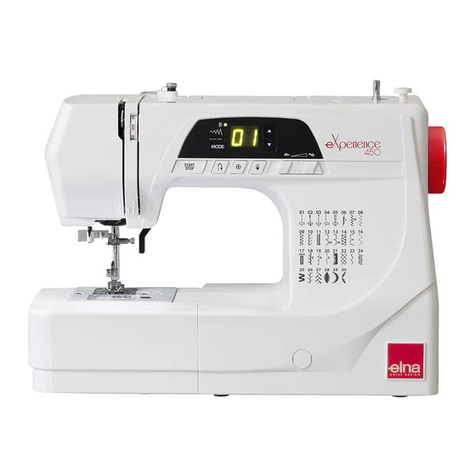
ELNA eXpressive 970 User manual

SERVICE MANUAL
MODEL: eXpressive 970
First Edition: 15 June 2016

1
CONTENTS
Replacing the Spool Stand...........................................................................................4
Replacing the Tension Unit Cover.................................................................................4
Replacing the Static head cover (Right) .......................................................................5
To Replace Right Cover and Left Cover .......................................................................6
Replacing the Base Cover and Bed Cover ...................................................................7
Checking the Thread Paths (1) .....................................................................................8
Checking the Thread Paths (2) .....................................................................................9
Replacing the Needle ................................................................................................. 10
Needle and Thread Reference Table .......................................................................... 11
Adjusting the Bobbin Thread Tension ......................................................................... 12
Checking the Lowest Position of the Needle .............................................................. 13
Replacing the Needle Bar Rest .................................................................................. 14
Replacing the Take-up Lever Cam Roller ................................................................... 15
Adjusting the Take up Lever Timing ............................................................................ 16
Replacing the Presser Foot Cam ...........................................................................17-19
Replacing and Adjusting the Presser Foot (1)............................................................ 20
Replacing and Adjusting the Presser Foot (2)............................................................ 21
Replacing the Presser Foot Return Spring and Washer.........................................22-24
Replacing the Thread Catcher.................................................................................... 25
Replacing the Thread Catcher Hook ......................................................................... 26

2
Replacing the Jump Solenoid..................................................................................... 27
Adjusting a Play in the Moving Head.......................................................................... 28
Replacing the Moving Head (1).................................................................................. 29
Replacing the Moving Head (2).................................................................................. 30
Adjusting the Needle Drop Position (Back or Forth) .................................................. 31
Adjusting the Needle Height....................................................................................... 32
Replacing the Needle Bar, Needle Spring and Cushion............................................. 33
Replacing the Rotation Stopper Plate ........................................................................ 34
Replacing the Thread Take-up Lever .......................................................................... 35
Adjusting the Check Spring Tension ........................................................................... 36
Adjusting the Check Spring Stroke ............................................................................ 37
Adjusting the Thread Catcher Holder ......................................................................... 38
Replacing the Thread Catcher Loop Tape .................................................................. 39
Replacing the Lateral Moving Unit.............................................................................. 40
Adjust the Hook Timing............................................................................................... 41
Adjusting the Position of the Hook Stopper ................................................................ 42
Replacing the Thread Cutter Driving Roller................................................................ 43
Replacing the Dynamic Cutter Blade.......................................................................... 44
Replacing the Static Cutter Blade............................................................................... 45
Adjusting the Static Cutter Blade................................................................................ 46
CONTENTS
3
Adjusting the Dynamic Cutter Blade........................................................................... 47
Adjusting the Bobbin Thread Holder........................................................................... 48
Adjusting the Thread Keeper ...................................................................................... 49
Adjusting the X-carriage Belt Tension......................................................................... 50
Replacing the X-carriage Belt..................................................................................... 51
Adjusting the Y-carriage Belt Tension.......................................................................... 52
Replacing the Y-carriage Belt...................................................................................... 53
Adjusting the Timing Belt Tnsion ................................................................................ 54
Replacing the Timing Belt........................................................................................... 55
Adjusting the Motor Belt Tension ................................................................................ 56
Replacing the Motor Belt ............................................................................................ 57
Replacing the DC Motor ............................................................................................. 58
To Reset Motor Drive Time ......................................................................................... 59
Adjusting the Needle Upper Shaft Timing................................................................... 60
Adjusting the Moving Head Stop Position................................................................... 61
Adjusting the Needle Stop Position ............................................................................ 62
Adjusting the Carriage Home Position........................................................................ 63
Securing the Cables in the Moving Head (Upper Part) .............................................. 64
PARTS LIST ......................................................................................................... 65-108
CONTENTS

4
Replacing the Tension Unit Cover
Setscrews
Spool stand
Tension unit cover
To remove:
1. Remove the setscrews and spool stand.
To attach:
2. Attach the spool stand and tighten the setscrews.
Setscrews
Replacing the Spool Stand
To remove:
1. Remove the setscrews and tension unit cover.
To attach:
2. Attach the tension unit cover and tighten the setscrews.
Setscrews

5
To remove:
1. Loosen the RCS mounting arm knob and remove it.
2. Remove caps, and two setscrews (A).
Remove the static head cover (right).
3. Disconnect the LED lamp connector and
K-board connector.
To attach:
4. Connect the LED lamp connector and K-board
connector.
5. Attach the static head cover (right) with the two
setscrews (A). Attach the caps.
6. Attach the RCS mounting arm knob.
Caps
Replacing the Static Head Cover (Right)
RCS mounting arm knob
Setscrews (A)
Hooks
LED lamp connector
K-board connector

6
Hook
Upper hook 1 Upper hook 2
Static head cover (right)
Right Cover
To remove:
1. Remove head cover (right).
Unhook the right cover from the right hook.
•Toremovetheheadcover,Unhookthecover
from upper hook 1, upper hook 2 and the
hook on handwheel side.
2. Remove caps and setscrews A.
Remove the right cover.
To attach:
3. Attach right cover with setscrews A and caps.
4. Attach the head cover (right).
•Donotbindcordswhenattachingtheheadcover
(right).
Left Cover
To remove:
1. Remove caps and setscrews B.
Remove the left cover.
To attach:
2. Attach left cover with setscrews B and caps.
Cap, Setscrews A
Cap, Setscrews B
To Replace Right Cover and Left Cover

7
Base Cover
To remove:
1. Remove the six setscrews (A).
2. Lift the back of the machine and remove it from the
base cover.
To attach:
3. Attach the machine into the base cover.
4. Tighten the six setscrews (A) securely.
Replacing the Base Cover and Bed Cover
Bed Cover
To remove:
1. Remove the setscrew A. Remove the bed cover.
To attach:
2. Attach the bed cover with the setscrew A.
Setscrews (A)
Setscrew A

8
A
Detecting roller
To avoid seam puckering, skipped stitches or thread
breaking, keep the thread paths in the best condition.
1. Tension control, detecting roller
a) Detecting rollers should spin smoothly.
b) Tension controls and detecting rollers
should be free of lint or dust.
2. Thread guide hole
a) There should be no burrs or scratches.
3. Thread take-up lever
a) There should be no burrs or scratches.
4. Lower guide plate
a) There should be no burrs or scratches.
5. Needle
a) The needle should not be bent or blunt.
To check the needle:
Touch the tip of the needle and slide it over on your nail
and slid it lightly.
The needle must be blunt if there is any scratch on your
nail after sliding the needle on your nail.
In that case, replace the needle.
Place the flat side of the needle onto something flat
(needle plate, glass, etc.). The gap (A) between the
needle and the flat surface should be consistent.
Replace the needle if the gap is not consistent.
Checking the Thread Paths (1)

9
6. Needle plate
a) There should be burrs or scratches.
7. Presser foot
a) There should be no burrs or scratches,
especially inside of the presser foot hole.
b) There should be no warp in the presser
foot.
8. Hook race
a) There should be no burrs or scratches.
b) The tip of hook race should not be blunt.
c) There should be no detectable play in the hook
and hook race.
9. Thread keeper
a) There should be burrs or scratches,
especially on the tip of the thread keeper.
10. Check spring
a) The check spring should not be worn.
Checking the Thread Paths (2)
Upper side
Lower side
Hook
Thread keeper

10
Replacing the Needle
To remove:
1. Loosen the needle clamp screw.
2. Remove the needle.
To attach:
3. Insert the needle into the needle clamp with the long
groove facing you. Push the needle up as far as it will
go.
4. Tighten the needle clamp screw.
Needle clamp screw
Needle
Long groove

11
Needle and Thread Reference Table
Use DBxK5Q1NY needles and select an appropriate size of
needle for threads and fabrics to be sewn.
An inappropriate size of needle may cause skip stitches,
thread breakage or loose seam.
Please refer to the table below and select the
suitable needle size.
75 8~10
120 9~11
200 11~14
Thread Size (Denier)
Polyester
Needle Size

12
* Use cotton thread size 120.
1. Guide the thread to the left to pass it into the guide
path as shown.
2. Pulling the thread from the front hole in the direction
of arrow, measure the thread tension with a tension
meter.
The thread tension should be in the range of 20 - 30gf.
If not, adjust the thread tension by turning the
adjusting screw.
1
2
Adjusting the Bobbin Thread Tension
Thread
Front hole
Tension meter
Front hole
Adjusting screw
Rear view
Guide path
Side view

13
Checking the Lowest Position of the Needle
1. Remove the spool stand, static head right cover and
left cover.
2. Turn the handwheel to set the index disk at 270°.
3. Push the needle bar down to engage the needle bar
clutch.
4. Turn the handwheel to set the needle bar at its lowest
position.
Use a lever type dial indicator to measure the needle
bar height.
5. Turn the handwheel clockwise until the indicator reads
0.2 mm and read the angle (Aº) of the index disk.
Turn the handwheel counterclockwise until the indicator
reads 0.2 mm and read the angle (Bº) of the index disk.
Calculate the mean angle (Cº): C=(A+B–360)÷2
Turn the handwheel clockwise to set the index disk at
Cº.
Loosen the two setscrews and set the pointer at 0º (L).
Tighten the two setscrews securely.
Check the following items if you have adjusted the
lowest position of the needle.
•Uppershafttiming
•Take-uplevertiming
•Hooktiming
•Threadcuttertiming
Lever type dial indicator
Setscrews Pointer

14
Replacing the Needle Bar Rest
To remove:
1. Remove spool stand, head cover (right), right cover and
left cover.
2. Disconnect the thread catcher unit connector.
Remove the two setscrews (A) and setscrew (B). Re-
move the thread catcher unit.
3. Loosen the setscrew (C). Pull the needle bar main shaft
up and remove it from the machine.
4. Loosen the setscrew (D) and remove the needle bar
rest from the needle bar main shaft.
To attach:
5. Reverse the procedure above. Attach the needle bar
main shaft so its bottom end is level with the bottom
surface of the head frame.
6. Adjust the needle height after the replacement.
Setscrews (A)
Connecter
Setscrew (B)
Needle bar main shaft
Setscrew (C)
Needle bar rest Setscrew (D)
Bottom of the head frame

15
To remove:
1. Remove spool stand, head cover (right), right cover, left
cover and thread tension panel.
2. Remove the three setscrews and drive cover.
3. Remove the thread take-up lever spring with pliers.
4. Loosen the setscrew. Remove the thread take-up lever
shaft, thread take-up lever unit and washer.
5. Loosen the setscrew. Remove the cam roller shaft and
cam roller.
To attach:
6. Reverse the procedure above.
When attaching the thread take-up lever shaft, tighten
the screw while pressing the thread take-up lever shaft
lightly.
Drive cover Setscrews
Thread take-up lever spring
Setscrew
Thread take-up lever shaft Thread take-up
lever unit
Cam roller
Cam roller
shaft
Setscrew
Washer
Thread take-up
lever shaft
Replacing the Take-up Lever Cam Roller

16
Adjusting the Take-up Lever Timing
To remove:
1. Remove spool stand, head cover (right), right cover and
left cover.
2. Turn the handwheel to set the index disk at 6º.
3. Insert the positioning pin from the left side of the arm.
The positioning pin goes into the pin groove of take-up
lever cam if the timing is correctly adjusted.
4. If the timing is incorrect, loosen the setscrew on the cam
clamp and turn the take-up lever cam so the positioning
pin can go into the pin grove on the cam.
Turn the handwheel to set the index disk at 6º. Tighten
the setscrew on the cam clump while pressing the
take-up lever cam to the side of the dynamic head.
There should be no gap between the take-up lever cam
and cam clamp.
5. Pull the positioning pin out from the arm.
Turn the handwheel to set the index disk at 270º.
Attach the removed parts.
Positioning pin
Pin groove
Take-up lever cam
Setscrew
Cam clamp
Take-up lever cam
Cam clamp

17
Replacing the Presser Foot Cam (1)
1Remove the spool stand, head set right cover, right cover,
left cover, moving head, thread catcher (unit)
and needle bar rest.
* The lateral moving unit is not needed to remove.
2 Remove the setscrews A (2 pcs.) and the left face plate.
3 Loosen the setscrew A. Pull the main shaft up.
Remove the presser foot block (unit).
4 Remove the snap ring E.
Loosen the setscrews B (2 pcs.).
Push the supporting shaft from the backside and pull the
supporting shaft out to the front.
Remove the presser foot lever (unit), poly slider and Rulon
washer.
Setscrew A Left face plate
Setscrew A Main shaft
Supporting shaft
Presser foot block
Presser foot lever (unit)
Setscrew B Snap ring E Poly slider
Rulon washer
Setscrew B
*The presser foot cam shall be replaced as the crank unit.

18
Replacing the Presser Foot Cam (2)
5 Loosen the setscrews C (2 pcs.).
6 Remove the setscrew B.
Pull the crank out to the front to remove it.
Setscrew C
Crank (unit)
Setscrew B

19
Replacing the Presser Foot Cam (3)
7Apply the grease to the groove of the presser foot cam.
* Recommended grease: MOLYKOTE (R) EM-30L.
8 Reverse the procedure to reinstall the parts.
Do not attach the covers yet.
9 Check the lowest position of the needle (refer to page
13 of service manual).
10 Adjust the position of the lateral moving unit (refer to
page 40 of service manual).
11 Attach the covers according to the procedures.
Other manuals for eXpressive 970
1
Table of contents
Other ELNA Sewing Machine manuals

ELNA
ELNA 740 EXCELLENCE - Operating and safety instructions

ELNA
ELNA Elnita ec60 User manual

ELNA
ELNA eXcellence 720PRO User manual

ELNA
ELNA 6600 User manual

ELNA
ELNA EnVision 8006 User manual

ELNA
ELNA Air Artist Installation guide

ELNA
ELNA 654 - User manual

ELNA
ELNA Lotus User manual

ELNA
ELNA 3210 User manual

ELNA
ELNA Xquisit II User manual