ELNA Elnita ec60 User manual

SERVICE MANUAL
MODEL: ec60
First Edition: 07 May 2020

INDEX
WHAT TO DO WHEN ......................................................................................................... 1 to 3
CHANGING EXTERNAL PARTS
FACE COVER ........................................................................................................................... 4
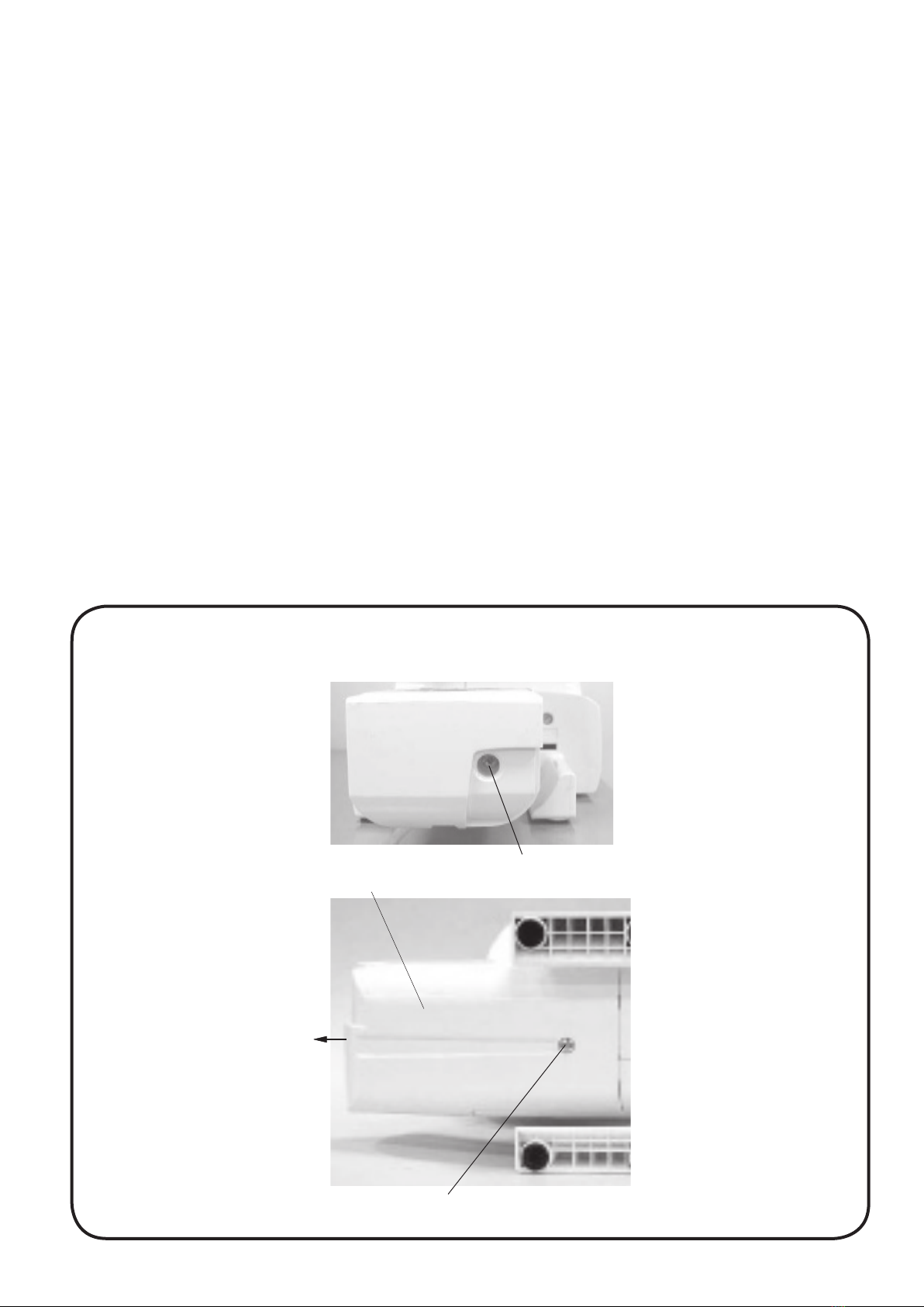
FREE ARM COVER ................................................................................................................. 5
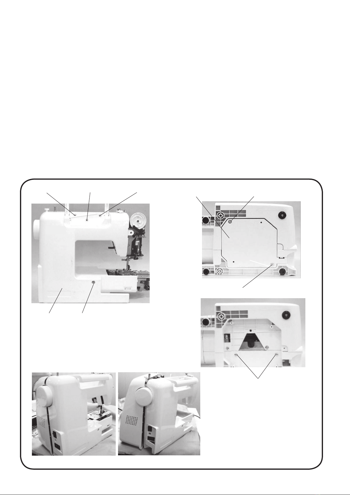
FRONT COVER ............................................................................................................... 6 to 7
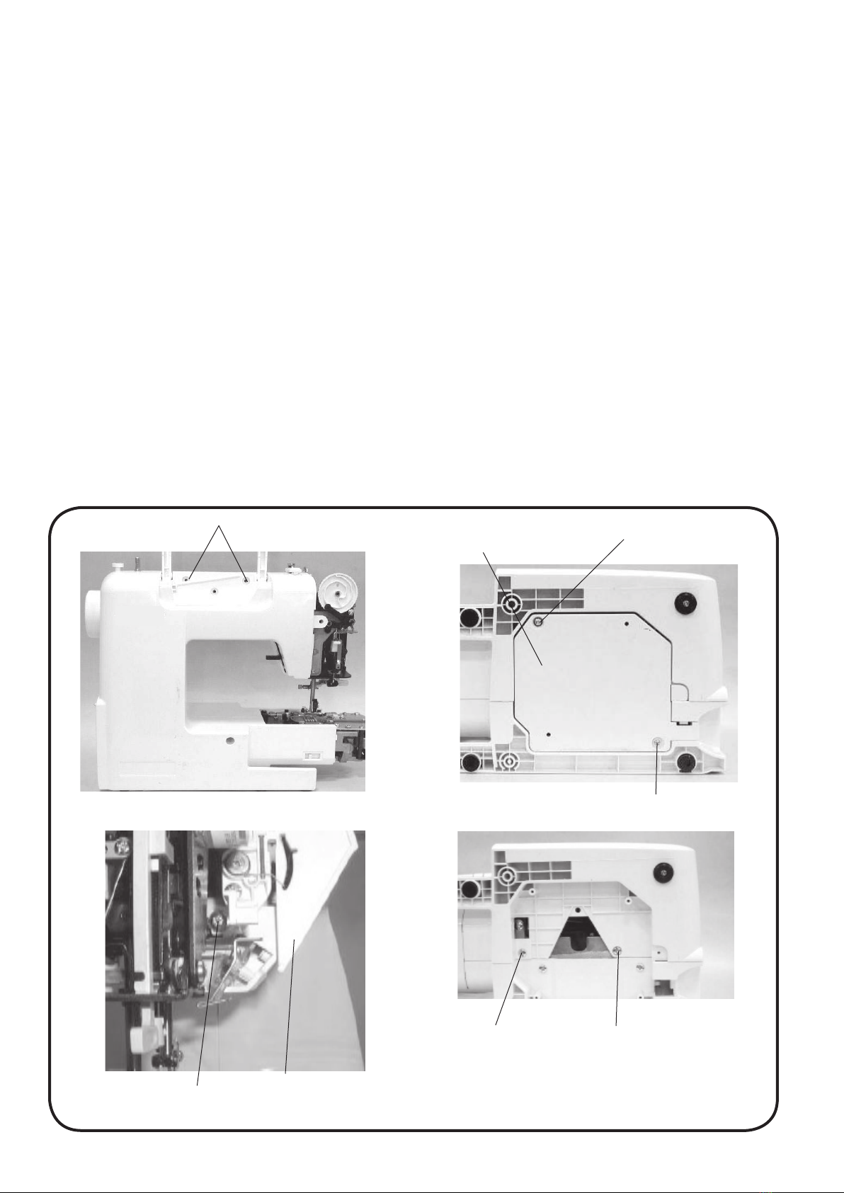
REAR COVER......................................................................................................................... 8
MECHANICAL ADJUSTMENT
PRESSER BAR HEIGHT ........................................................................................................ 9
NEEDLE DROP POSITION..................................................................................................... 10
ADJUSTMENT OF HOOK TIMING ......................................................................................... 11
ADJUSTMENT OF NEEDLE BAR HEIGHT ........................................................................... 12
CLEARANCE BETWEEN NEEDLE AND TIP OF HOOK ROTARY ........................................ 13
FEED DOG HEIGHT ............................................................................................................... 14
FEED DOG ADJUSTMENT ..................................................................................................... 15
TOP TENSION ........................................................................................................................ 16
REPLACING THE ELECTRONIC COMPONENTS
CIRCUIT BOARD-A CONNECTION........................................................................................ 17
SELF-DIAGNOSTIC TEST.............................................................................................. 18 to 22
CIRCUIT BOARD-A........................................................................................................ 23 to 24
DRIVING MOTOR ................................................................................................................... 25
SWITCHING REGULATOR UNIT ........................................................................................... 26
ADJUSTING BUTTONHOLE LEVER POSITION.................................................................... 27
PARTS LIST................................................................................................................... 28 to 41

1
CONDITION CAUSE HOW TO FIX REFERENCE
1. SKIPPING
STITCHES
1. NEEDLE IS NOT INSERTED
PROPERLY.
2. NEEDLE IS BENT OR WORN.
3. INCORRECTLY THREADED.
4. NEEDLE OR THREAD ARE
INAPPROPRIATE FOR THE
FABRIC BEING SEWN.
5. SEWING ON
STRETCH FABRIC.
6. INAPPROPRIATE NEEDLE
BAR HEIGHT.
7. INAPPROPRIATE NEEDLE TO
HOOK TIMING.
8. INAPPROPRIATE NEEDLE TO
HOOK CLEARANCE.
INSERT THE NEEDLE PROPERLY.
CHANGE THE NEEDLE.
RETHREAD.
USE THE RECOMMENDED SEWING
NEEDLE AND THREAD.
USE A HA X #11 BLUE TIP NEEDLE.
SEE MECHANICAL ADJUSTMENT
“ADJUSTMENT OF NEEDLE BAR
HEIGHT”.
SEE MECHANICAL “ADJUSTMENT OF
HOOK TIMING”.
SEE MECHANICAL ADJUSTMENT
“CLEARANCE BETWEEN NEEDLE
AND TIP OF THE ROTARY HOOK”.
P. 12
P. 11
P. 13
2. FABRIC NOT
MOVING
1. INCORRECT FEED DOG
HEIGHT.
2. FEED DOG IS IN DOWN
POSITION.
3. THREAD ON BOTTOM SIDE OF
FABRIC IS JAMMED UP.
4. FEED DOG TEETH ARE WORN.
SEE MECHANICAL ADJUSTMENT
“FEED DOG HEIGHT”.
RAISE THE FEED DOG.
MAKE SURE TO BRING BOTH NEEDLE
AND BOBBIN THREADS UNDER THE
FOOT WHEN START SEWING.
CHANGE THE FEED DOG.
P. 14
WHAT TO DO WHEN

2
CONDITION CAUSE HOW TO FIX REFERENCE
3. BREAKING
UPPER
THREAD.
1. INITIAL SEWING SPEED IS
TOO FAST.
2. THREAD PATH IS INCORRECT.
3. NEEDLE IS BENT OR DULL.
4. TOP TENSION IS TOO STRONG.
5. NEEDLE SIZE IS
INAPPROPRIATE FOR FABRIC.
6. NEEDLE EYE IS WORN.
7. NEEDLE HOLE IN NEEDLE
PLATE IS WORN OR BURRED.
START WITH MEDIUM SPEED.
USE THE PROPER THREAD PATH.
REPLACE WITH A NEW NEEDLE.
ADJUST TOP TENSION CORRECTLY.
USE APPROPRIATE NEEDLE FOR
FABRIC AND THREAD IN USE.
CHANGE THE NEEDLE.
REPAIR THE HOLE OR REPLACE THE
NEEDLE PLATE.
4. BREAKING
BOBBIN
THREAD.
1. BOBBIN HOLDER IS
INCORRECTLY THREADED.
2. TOO MUCH THREAD IS WOUND
ON THE BOBBIN.
3. LINT IS STUCK INSIDE THE
BOBBIN HOLDER.
4. THREAD QUALITY IS TOO LOW.
5. THREAD IS JAMMING AROUND
THE BOBBIN HOLDER.
SET THE BOBBIN THREAD
CORRECTLY.
ADJUST THE POSITION OF BOBBIN
WINDER STOPPER.
CLEAN THE BOBBIN HOLDER.
CHANGE TO A HIGH QUALITY SEWING
THREAD.
CLEAR OUT THE JAMMING THREAD.
5. NEEDLE
BREAKS
1. NEEDLE IS HITTING THE
NEEDLE PLATE.
2. NEEDLE IS BENT OR WORN.
3. NEEDLE IS HITTING THE HOOK.
4. FABRIC IS BEING PULLED TOO
STRONGLY WHILE SEWING.
SEE MECHANICAL ADJUSTMENT
“NEEDLE DROP POSITION”.
CHANGE THE NEEDLE.
SEE MECHANICAL ADJUSTMENT
“CLEARANCE BETWEEN NEEDLE AND
TIP OF THE ROTARY HOOK”.
GUIDE THE FABRIC GENTLY WHILE
SEWING.
P. 10
P. 13

3
CONDITION CAUSE HOW TO FIX REFERENCE
6. NOISY
OPERATION
1. BACKLASH BETWEEN HOOK
GEAR AND LOWER SHAFT
GEAR IS TOO GREAT.
2. LOWER SHAFT GEAR IS
LOOSE.
3. INAPPROPRIATE BELT
TENSION.
4. NOT ENOUGH OIL.
5. UPPER SHAFT GEAR IS LOOSE.
ELIMINATE THE BACKLASH.
ELIMINATE THE LOOSENESS.
SEE PART REMOVAL AND
REPLACEMENT
“DRIVING MOTOR (DC MOTOR)”.
OIL ALL MOVING PARTS.
ELIMINATE THE LOOSENESS.
P. 25
7. DEFORMATION
PATTERN
1. INAPPROPRIATE FEED
BALANCE.
2. TOP TENSION IS TOO STRONG.
ADJUST THE FEED BALANCING
SCREW.
SEE MECHANICAL ADJUSTMENT
“TOP TENSION”.
P. 16

4
CHANGING EXTERNAL PARTS
FACE COVER
TO REMOVE:
1. Remove the setscrew (A) and lift the face cover to disengage the rib on the inside.
Remove the face cover (B).
TO ATTACH:
2. Follow the above procedures in reverse.
(A)
(B)

5
CHANGING EXTERNAL PARTS
FREE ARM COVER
TO REMOVE:
1. Remove the setscrew (A) (2 pcs). Move the free arm cover (B) to the left and remove the free arm
cover.
TO ATTACH:
2. Follow the above procedures in reverse.
(A)
(A)
(B)

6
Thread tension unit
CHANGING EXTERNAL PARTS
FRONT COVER (1)
TO REMOVE:
1. Remove the face cover and free arm cover (see pages 4 and 5).
2. Remove the setscrews (A) (2 pcs.).
3. Remove the setscrews (B) (2 pcs.) and back cover (C).
4. Remove the setscrews (D) (2 pcs.).
5. Loosen the setscrew (E).
(A) (B)
(B)
(C)
(D) (D)
(E)

7
CHANGING EXTERNAL PARTS
FRONT COVER (2)
6. Disengage the front cover and rear cover hooks.
7. Disconnect all the connectors from the printed circuit board A.
NOTE: Do not disconnect the connectors by pulling on cord.
To disconnect, grasp the connector, not the cord.
8. Remove the front cover.
TO ATTACH:
9. Follow the above procedures in reverse. Remove the front cover.

8
CHANGING EXTERNAL PARTS
REAR COVER
TO REMOVE:
1. Remove the face cover and free arm cover (see pages 4 and 5).
2. Remove the setscrews (A) (2 pcs.).
3. Remove the setscrews (B) (2 pcs.).
4. Remove the setscrews (C) (2 pcs.) and back cover.
5. Remove the setscrews (D) (2 pcs.) and the rear cover.
TO ATTACH:
5. Follow the above procedures in reverse.
Back cover
Rear cover
(A)
(B)
(C)
(C)
(D)
(A)(B)

9
6.0 mm
MECHANICAL ADJUSTMENT
PRESSER BAR HEIGHT
The distance between the bottom of the presser foot in up position and the needle plate should be 6.0 mm.
TO REMOVE:
1. Remove the face plate and needle.
2. Lower the feed dog below the needle plate. Place a block 6 mm thick under the presser foot and
lower the presser foot lifter (A).
3. Loosenthesetscrew(B).Raisethepresserfootlifterandtightenthesetscrew(B)rmly.
TO ATTACH:
4. Attach the needle and face plate.
NOTE: Make sure that the presser foot should be parallel to the feed dog slot in the needle plate.
Presser foot should be parallel to
the feed dog slot.
(A)
(B)

10
0.2 mm
or more
0.2 mm
or more
A = B
MECHANICAL ADJUSTMENT
NEEDLE DROP POSITION
Set the stitch pattern to “ ”. The standard needle drop position should be at center of the needle
plate hole (A). Select zigzag stitch “ ”, and set the stitch width at “7.0”. The clearance between the
needle and the edge of the needle hole in the needle plate should be at least 0.2 mm on either side. If
not, adjust as follows:
1. Turn the power switch off. Remove the face cover (see page 4.)
2. Loosen the hexagonal socket screw 3x4 (B). Adjust the needle drop position by turning the
eccentric pin.
The direction of eccentric pin should be as shown in Fig. 1.
3. Attach the face cover.
NOTE:
Check the hook timing after this adjustment.
Fig. 1
(A)
(B)
Rotation center
Eccentric Between the range of
downward direction
Eccentric pin

11
MECHANICAL ADJUSTMENT
ADJUSTMENT OF HOOK TIMING
The amount of ascending travel of the needle bar from its lowest position to the position ( ) where the
tip of the rotary hook exactly meets the right side of the needle should be 3.25 to 3.55 mm.
TO ADJUST:
1. Remove the free arm cover (see page 5).
2. Remove the needle plate and bobbin holder.
3. Turn the power switch on.
4. Select the pattern (left position). Set the zigzag width at 0.
5. Remove the free arm cover
Turn the handwheel toward you to lower the needle at its lowest position.
6. Loosen the hexagonal socket screw (A) (2 pcs.).
7. Move the needle bar 3.4 mm from the lowest position.
8. Turn the lower shaft gear until the tip of hook meets the right side of the needle while holding the
handwheel.
9. Tighten the hexagonal socket screw (A) (2 pcs.).
10.Attach the free arm cover, bobbin holder and needle plate.
(A)
Needle plate
Bobbin holder
(A)
Lower shaft gear
Left position ( )
(#14)
Tip of hook meets the
right side of the needle
Lowest needle position
3.25 to 3.55 mm

12
MECHANICAL ADJUSTMENT
ADJUSTMENT OF NEEDLE BAR HEIGHT
Before proceeding with this adjustment, check the hook timing (see page 11). The distance
between the upper edge of the needle eye and the tip of the hook should be in the range of 1.6 to
2.0 mm when the tip of the hook timing meets right side of the needle in the left needle position ( )as
the needle ascends from its lowest position.
TO ADJUST:
1. Remove the needle plate, bobbin holder and face plate.
2. Turn the power switch on.
3. Select the pattern (left position). Set the zigzag width at 0.
4. Turn the handwheel toward you until the tip of hook meets the right side of the needle.
5. Loosen the hexagonal socket screw.
6. Move the needle bar to adjust the needle bar height, and tighten the hexagonal socket screw.
Be careful not to turn the needle bar.
7. Attach the bobbin holder, needle plate and face cover.
1.6 to 2.0 mm
Hexagonal socket screw
Needle setting
groove
Upper edge of needle hole
Hook race (unit)
Hook race
Tip of hook meets the right side of the needle
Left position ( )
(#14)
Needle plate
Bobbin holder

13
MECHANICAL ADJUSTMENT
CLEARANCE BETWEEN NEEDLE AND TIP OF THE ROTARY HOOK
* The clearance between the needle and the point of hook should be –0.10 to +0.05 mm.
ADJUSTMENT PROCEDURE:
1. Remove the needle plate and bobbin holder. Attach the master needle. Turn the power switch on
and set the zigzag width at maximum.
2. Remove the face cover (see page 4).
3. Loosen the setscrew (A) (2 pcs.).
4. Turn the handwheel toward you. Adjust the clearance between the needle and the tip of the rotary
hook, by moving the hook base plate up or down, to within –0.10 to +0.05 mm at the left and right
needle position.
5. Tighten the setscrew (A) (2 pcs.).
6. Attach the face cover. Remove the master needle. Attach the bobbin holder and needle pate.
7. Check the clearance between the needle and the edge of the needle hole in the needle plate (see
page 10).
Tip of hook
–0.10 to +0.05 mm
Needle bar supporter
adjusting plate
Setscrew (A)
Needle plate
Bobbin holder

14
MECHANICAL ADJUSTMENT
FEED DOG HEIGHT
The highest position of the feed dog should be between 0.80 and 0.90 mm from the surface of the needle
plate.
1. Lower the presser foot and turn the power switch on.
2. Turn the handwheel toward you to set the feed dog at the highest position.
3. Remove the free arm cover.
4. Loosen the setscrew (A) and nut (B).
5. Adjust the feed dog height by turning the adjusting screw (C). The highest position of the feed dog
should be between 0.80 and 0.90 from the surface of the needle plate.
6. Tighten the nut (B) and setscrew.
7. Attach the free arm cover.
(A)
(C)
(B)
Presser foot
Feed dog
0.80 to 0.90 mm
Surface of the needle
plate
(A)

15
MECHANICAL ADJUSTMENT
FEED DOG ADJUSTMENT
The highest position of the feed dog should be parallel to the surface of the needle plate.
If not, adjust as follows.
1. Use a hexagonal socket screw (4 x 6).
Insert the screw to the hole B. Tighten the hexagonal socket screw as far as it goes.
2. Loosen the setscrew C.(left screw)
3. Turn hexagonal socket screw to adjust the feed dog (should be parallel to the surface of the needle
plate).
4. Tighten the setscrew C (left screw).
5. Loosen the hexagonal socket screw and remove it.
Hole B
Hexagonal socket screw 4x6
Setscrew C (left screw)

16
MECHANICAL ADJUSTMENT
TOP TENSION
The top tension should be between 65 and 80 grams-force when pulling the thread up in the direction
of C.
* Use polyester sewing thread #50 (White).
* If it is not within the above limit, adjust as follows.
1. Set the tension dial “Auto”.
2. Remove the front cover (see pages 6 and 7).
3. Lower the presser foot.
• If the top tension is too loose, turn the lead screw in the direction (A).
• If the top tension is too tight, turn the lead screw in the direction (B).
4. Check the top tension and attach the cover.
White polyester thread size 50
Pull the thread at the speed of 110 mm/sec in the
direction of arrow.

17
REPLACING THE ELECTRONIC COMPONENTS
PRINTED CIRCUIT BOARD A CONNECTION
NOTE: Do not disconnect the connectors by pulling on cord.
To disconnect, grasp the connector, not the cord.
r
yu
i
o
!0
!1 Printed circuit board A
Printed circuit board F
Printed circuit board L
qPRINTED CIRCUIT BOARD P
wFEED MOTOR
eTHREAD CUTTER MOTOR
rBOBBIN WINDING SWITCH
tPOWER SWITCH
yZIGZAG WIDTH MOTOR
u SOLENOID
i PRINTED CIRCUIT BOARD F
o PRINTED CIRCUIT BOARD L
!0 PROGRAM
!1 BUTTONHOLE SENSOR PROGRAM
!2 PRESSER FOOT LIFTER SWITCH
!3 DC MOTOR
!4 CONTROLLER
q
w
e
t
!2
!3!4

18
TO ENTER SELF-DIAGNOSTIC MODE:
SELF-DIAGNOSTIC TEST
PREPARATION:
1. Turn the power switch off.
2. Move the bobbin winder spindle to the left.
3. Raise the feed dog.
4. Set the speed control lever to the left.
5. Remove the presser foot and raise the presser foot lifter.
6. Turn the hand wheel toward you to raise the needle to its highest position.
NOTES:
• Be careful: the sewing machine may start running in its own while in test mode.
• Turn off the power switch before replacing any parts.
• Repeat the diagnostic test until the problem has been resolved.
• You can skip steps in the diagnostic procedure and go directly to the test you want to perform.
(Enter self-diagnostic mode, then select the step number of the diagnostic test you require by
pressing the start/stop button)
TO BEGIN:
Turn on the switch, if any of the following problems occur, take the recommended actions in the
order they are shown.
1. The machine does not respond when the power switch is turned on:
• Check each connector connection.
• Replace the machine socket.
• Replace the switching regulator.
• Replace the printed circuit board A.
2. The sewing machine lamp does not light up:
• Replace the printed circuit board L.
• Replace the printed circuit board A.
Turn the power switch on while
simultaneously pressing needle
up/down button and the locking
stitch button.
The LCD display will
indicate “01”.
Press the start/stop button to
enter the self-diagnostic mode.
Table of contents
Other ELNA Sewing Machine manuals