ELNA 6001 User manual

PDFMAILER.DE
ELNA
6001
SERVICE MANUAL
10/2002 Printed in Switzerland 395 903-02

PDFMAILER.DE
Notes:

PDFMAILER.DE
I N D E X
WIRING DIAGRAM 1
GENERAL TROUBLE SHOOTING PROCEDURE 2
WHAT TO DO WHEN 3-4
ELECTRONIC QUICK CHECK 5-7
SERVICE ACCESS 8-12
FACE COVER 8
TOP COVER 8
BELT COVER 9
BASE PLATE 10
BED COVER 10
FRONT COVER 11
REAR COVER 12
MECHANICAL ADJUSTMENT 13-23
NEEDLE POSITION 13
NEEDLE BAR HEIGHT 14
NEEDLE TO SHUTTLE TIMING 15
CLEARANCE BETWEEN NEEDLE AND HOOK 16
BACKLASH (LOWER SHAFT GEAR) 17
FEED DOG HEIGHT 18
ZIGZAG SYNCHRONIZATION 19
STRETCH STITCH FEED BALANCE 20
UPPER THREAD TENSION 21
BUTTONHOLE 22
PRESSER BAR HEIGHT AND ALIGNMENT 23
PART REMOVAL AND REPLACEMENT 24-33
THREADER PLATE 24
A-BOARD AND FUSE 25
TRANSFORMER 26
MACHINE SOCKET 27
K-BOARD 28
F-BOARD 28
DRIVING MOTOR (DC MOTOR) 29
BUTTONHOLE SENSOR 30
UPPER SHAFT SENSOR 31
ZIGZAG STEPPING MOTOR 32
FEED STEPPING MOTOR 33

PDFMAILER.DE
WIRING DIAGRAM
NAME OF ELECTRONIC PARTS AND WIRING
EACH CONNECTOR SHOULD BE CONNECTED AS FOLLOWS ;
A: BUTTONHOLE SENSOR G: TRANSFOMER (PRIMARY)
B: UPPER SHAFT SENSOR H: TRANSFOMER (SECONDARY)
C: SEWING LIGHT I : RECEPTACLE (PRIMARY)
D: FEED STEPPING MOTOR J : RECEPTACLE (SECONDARY)
E: ZIGZAG STEPPING MOTOR K: K-BOARD
F: DC MOTOR L: F-BOARD
1

PDFMAILER.DE
GENERAL TROUBLE SHOOTING PROCEDURE
(MACHINE DOESN’T WORK WELL)
2

PDFMAILER.DE
WHAT TO DO WHEN
CONDITION CAUSE HOW IS FIX REFERENCE
1. Skipping
stitches 1. Needle is not inserted
properly.
2. Needle is bent or worn.
3. Incorrectly threaded
4. Needle or thread are
inappropriate for fabric
being sewn.
5. Sewing on stretch fabric.
6. Presser foot pressure is
tooweak.
7. Inappropriate needle bar
height.
8. Inappropriate needle to
shuttle timing.
9. Inappropriate needle to
shuttle clearance
Insert the needle properly
Change the needle
Rethread
Use the recommended sewing
needle and thread
Use a #11 blue tip needle
Adjust the presser bar level to
make the pressure stronger
See mechanical adjustment
“NEEDLE BAR HEIGHT”
See mechanical adjustment
“NEEDLE TO SHUTTLE TIMING”
See mechanical adjustment
“CLEARANCE BETWEEN NEEDLE
AND HOOK”.
Page 14
Page 15
Page 16
2. Fabric not
moving. 1. Presser foot pressure is
tooweak.
2. Incorrect feed dog height.
3. Feed dog is indown
position.
4. Thread on bottom side of
fabric isjammed up.
5. Feed dog teeth are worn.
Adjust the presser bar level to
make the pressure stronger.
See mechanical adjustment “FEED
DOG HEIGHT”.
Raise the feed dog lever.
Make sure to bring both needle and
bobbin thread under the foot when
starting sewing.
Change the feed dog.
Page 18
3. Breaking upper
thread. 1. Initial sewing speed is
too fast.
2. Thread path is incorrect
3. Needle is bent or dull.
4. Upper tension is too
strong.
5. Needle size is
inappropriate for fabric.
6. Needle eye isworn.
7. Needle hole in needle
plate is worn or burred
Start with medium speed
Use the proper thread path.
Replace with a new needle.
Adjust needle thread tension
correctly.
Use appropriate needle for fabric
and thread in use.
Change the needle.
Repair the hole or replace the
needle plate.
Page 21
3

PDFMAILER.DE
CONDITION CAUSE HOW IS FIX REFERENCE
4. Breaking bobbin
thread. 1. Incorrectly threaded
bobbin.
2. Too much thread is
around on the bobbin.
3. Lint is stuck inside the
bobbin holder.
4. Thread quality is too low.
5. Thread is jamming
around the bobbin.
Thread bobbin correctly.
Adjust the bobbin winding stopper.
Clean the shuttle.
Change to a high quality sewing
thread.
Clear out thejamming thread.
5. Needle breaks. 1. Needle is hitting the
needle plate.
2. Needle is bent or worn.
3. Needle is hitting the
shuttle.
4. The fabric moves while
the needle is piercing it,
or the needle zigzags
while in fabric.
5. Fabric is being pulled too
strongly while sewing.
See mechanical adjustment
“NEEDLE POSITION”.
Change the needle.
See mechanical adjustment
“CLEARANCE BETWEEN NEEDLE
AND HOOK”.
See mechanical adjustment “
ZIGZAG SYNCHRONIZATION”.
Guide the fabric gently while
sewing.
Page 13
Page 16
Page 19
6. Noisy operation. 1. Backlash between shuttle
hook gear and lower
shaft gear is too great.
2. Lower shaft gear is
loose.
3. Inappropriate belt
tension.
4. Not enough oil
See mechanical adjustment
“BACKLASH (LOWER SHAFT
GEAR)”.
Eliminate the looseness.
See part removal and replacement
“DRIVING MOTOR (DC MOTOR)”.
Oil all moving parts.
Page 17
Page 29
7. Deformation
pattern. 1. Inappropriate feed
balance.
2. Inappropriate zigzag
synchronization.
3. Upper thread tension is
too strong.
See mechanical adjustment
“STRETCH STITCH FEED
BALANCE”.
See mechanical adjustment
“ZIGZAG SYNCHRONIZATION”
See mechanical adjustment
“NEEDLE THREAD TENSION”.
Page 20
Page 19
Page 21
4

PDFMAILER.DE
SELF DIAGNOSTIC TESTS
PREPARATION
•Turn off the power switch.
•Shift the bobbin winder spindle to the left.
•Raise the feed dog.
•Shift the slide volume to the left.
•Remove the presser foot and raise the presser foot lifter.
•Turn the handwheel toward you to raise the needle to its highest position.
•Connect the foot controller to the machine.
NOTE
•Be careful: The sewing machine may start running in its own while in test mode.
•Turn off the power switch before replacing any parts.
•Repeat the diagnostic test until the problems has been resolved.
•You can skip steps in the diagnostic procedure and go directly to the test you want to
perform.
•(Enter Self-Diagnostic mode, then press the needle up/down button until the step number
of the required test is indicated).
PRELIMINARY TEST:
Turn on the power switch. If any of following problems occur, take the recommended actions in
the order they are shown.
The machine does not respond when the power switch is turned on.
1. Check each connector connection.
2. Replace the machine socket.
3. Replace the A-board.
4. Replace the machine socket.
5. Replace the power transformer.
The sewing machine light does not light up.
1. Replace the lamp.
2. Replace the A-board.
The display shows to
1. Replace the A-board.
TO ENTER THE SELF.DIAGNOSTIC MODE:
If you do not press the next button within 2,5 sec, the machine will revert to normal sewing mod,
should this occur, start over again from Step No. 1.
No. 1.
Turn the power switch on while
simultaneously pressing the
needle up/down button and the
reverse button.
No. 2.
Press the reverse button five
times to select menu item “6”.
No. 3.
Press the needle up/down
button
5

PDFMAILER.DE
SELF DIAGNOSTIC SHEET
STEP PROCEDURE CORRECT CONDITION DEFECTIVE CONDITION
01
7 Segment LED Turn on the power switch while
simultaneously pressing the
needle up/down button and the
reverse button.
Press the reverse button five
times to select menu item “6”.
Press the needle up/down
button: the LED indicates “01”
for one second.
If you don’t press the reverse
button within 2.5 seconds, the
machine automatically reverts
to normal sewing mode.
•
Beep sounds when the buttons
are pressed.
•
LED displays “8.8”, and blinks in
1-sec intervals.
•
No beep sound.
•
Does not enter
Self-Diagnostic mode.
•
LED does not blink on or
off.
1. Replace A-board.
02
MODE LED Press needle up/down button,
LED displays “02” for one
second.
7-segment LED displays “Ld”.
3 mode LED blink in 1-sec.
intervals.
•
LED does not blink.
1. Replace A-board
03
SWITCH Press needle up/down button,
LED displays “03” for one
second.
Press buttons S1to S8.
•
LED indicates [-----].
•
Button number is displayed
when the button is pressed.
•
•
LED display is different
from that shown to the left.
•
1. Replace A-board.
04
BOBBIN
WINDER
SWITCH
Press needle up/down button,
LED displays “04” for one
second.
•
Move the bobbin winder
spindle to the right.
•
Return it to the left.
LED indicates”II” LED display is different from that
shown to the left.
1. Adjust bobbin winder
switch position.
2. Replace bobbin winder
switch.
3. 3. Replace A-board.
05
NOT
APPLICABLE
TO THIS
MODEL
Skip this step by pressing the
needle up/down button.
06
BUTTONHOLE
SENSOR
Press needle up/down button,
LED displays “06” for one
second.
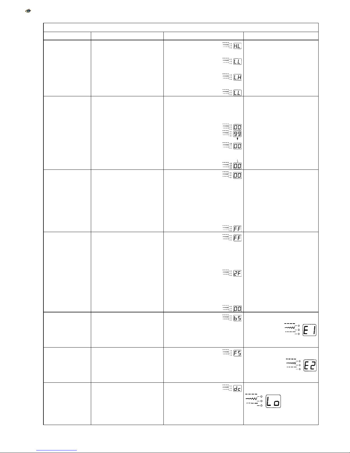
1. Lower the buttonhole lever.
2. Move the buttonhole lever
back and forth.
When the buttonhole lever
is pulled, LED displays “H”.
When the buttonhole lever
is free (center).
When the buttonhole lever
is pushed LED displays H.
LED display is different from that
shown to the left.
1. Adjust the buttonhole sensor
position.
2. Replace buttonhole sensor.
3. Replace A-board.
6

PDFMAILER.DE
SELF DIAGNOSTIC SHEET
STEP PROCEDURE CORRECT CONDITION DEFECTIVE CONDITION
07
UPPER SHAFT
SENSOR
Press the needle up/down
button, LED displays “07” for
one second.
•
Turn the handwheel toward
you to raise and lower the
needle to its highest and
lowest position.
When the needle is at
the highest position,
LED displays “LH”.
When the needle is at
lowest position,
LED displays “LH”.
When the needle is
halfway,
LED displays “LL”.
LED display is different from that
shown to the left.
1. Adjust the buttonhole sensor
position.
2. Replace buttonhole sensor.
3. Replace A-board.
LED displays “00” first and the
indicates value increases as you
turn the handwheel.
08
SEWING
SPEED
CENSOR
Press the needle up/down
button. LED displays “08” for
one second.
Turn the handwheel clockwise
by hand and check the counter
value displayed by the LED.
(When the value
reaches 100, it will
return to “00” and one
mode LED lights up.
For example, 2 mode
LED and “78” means
“278”).
The maximum value
should be 370 to 390.
LED displays different from that
shown to the left.
1. Replace motor.
2. Replace A-board.
09
SLIDE VOLUME Press needle up/down button,
LED displays “09” for one
second.
Slide the speed control lever
from left to right, then return it
to the left.
When the speed control
lever is at the left, LED
displays “00”.
The indicated value
increases as you move
the speed control lever
to the right, and finally it
shows “FF” when the
lever reaches the right-
most position.
LED display is different from that
shown to the left.
1. Replace slide volume. foot
control.
1. Replace A-board.
10
FOOT
CONTROLLER
Press needle up/down button.
The LED displays “10” for one
second.
Depress the foot controller down all
the way and release.
When the foot control is
not depressed, LED
should display “F0” to
“FF” (Hexadecimal
value).
When the foot control is
fully depressed, LED
should display “05” to
“2F”. When the control is
disconnected, LED
should show “00” to
“04”.
LED display is different from that
shown to the left.
1. Replace foot control.
2. Replace machine socket.
3. Replace A-board.
11
ZIGZAG
MOTOR
Press the needle up/down
button, the LED displays “11”
for one
second.
press the start/stop button.
LED displays.
Zigzag width motor is
set to the initial position.
(Needle centered.)
LED display is different from that
shown to the left.
If LED displays “E1”,
replace motor or A-board.
FEED MOTOR Turn the handwheel toward you
to lower the needle to its lowest
position, then press start/stop
button.
LED displays “FS”.
Feed motor is set to
the initial position
(stitch length: 0)
LED display is different from that
shown to the left.
If LED display is E2
Replace motor or board.
12
DC MOTOR Press needle up/down button,
LED indicates “12” for one
second.
*Press foot control.
LED indicates “dc”.
Machine runs at the
speed set by speed
control lever.
Full left: 80 ~100spm
Full right 800~840 spm
Machine does not run, LED
displays “Lo”.
Replace motor or A-board.
7

PDFMAILER.DE
FACE AND TOP COVER
FACE COVER
1. Remove the cap and set screw (A).
2. Remove the face plate while pulling it toward you so that face plate hook is released.
TO ATTACH
1. Attach the face plate.
2. Tighten the setscrew (A) and attach the cap.
TOP COVER
TO REMOVE
1. Remove the setscrew (B).
2. Lift up the handle and remove the setscrew (C).
3. Close the top cover lid and pull the top cover to the back.
TO ATTACH
1. Lift up the handle and insert the top cover from the back.
2. Tighten the setscrews (B) and (C).
8

PDFMAILER.DE
BELT COVER
TO REMOVE
1. Remove the cap.
2. Remove the setscrew (A) and (B).
3. Lift up the handle and loosen the setscrew the belt cover.
TO ATTACH
1. Attach the belt cover with the setscrew (A), (B) and (C).
9

PDFMAILER.DE
BASE PLATE AND BED COVER
BASE PLATE
TO REMOVE
1. Remove the setscrew (A) and 4 screws (B).
2. Remove the base plate (C).
TO ATTACH
3. Reverse this procedure.
BED COVER
TO REMOVE
1. Remove the 2 screws (D).
2. Remove the bed cover (E).
TO ATTACH
1. Move the drop lever (F) to the left and attached the bed cover with
2. 2 screws (D).
10

PDFMAILER.DE
FRONT COVER
FRONT COVER
TO REMOVE
1. Remove the face cover, top cover, belt cover and bed cover (see page 8, 9 and 10).
2. Remove the set screw (A) and loosen the setscrews (B), (C), (D), (E), (F) and (G).
3. Pull out connector (H)and remove the front cover.
TO ATTACH
1. Reverse this procedure.
11

PDFMAILER.DE
REAR COVER
TO REMOVE
1. Remove the face cover, top cover, belt cover and bed cover. (See pages 8, 9 and 10.)
2. Loosen the setscrews (A), (B), (C) and (D).
2. Remove the cap, setscrew (E) and set screw (F).
3. Remove the rear cover while pulling it toward you and pushing it to the left.
4. (Unhook the projection (G) and twist the rear the cover to clear the presser bar lifter area.)
TO ATTACH
1. Reverse this procedure.
12

PDFMAILER.DE
NEEDLE POSITION
When straight stitch (----) is selected, needle should be in the middle of needle plate hole.
When the machine is set for maximum zigzag width, the clearance between needle at the left and
right should be minimum 0.2 mm.
1. Remove the face plate.
2. Turn on the power switch.
3. Select pattern No.1 (straight stitch), and check the needle drop.
4. Select pattern No.2 (simple zigzag) and check the clearance between needle and needle plate
at the left and right sides.
5. Loosen the setscrew (A) and turn the eccentric pin to adjust the needle drop.
6. Tighten the setscrew (A).
7. Attach the face plate.
13

PDFMAILER.DE
NEEDLE BAR HEIGHT
The distance between the upper edge of needle eye and the tip of the hook should be in the range
of 1.6-2.0 mm when the tip of hook meets the right side of the needle in ascending travel of needle
from its left and lowest position.
2. Remove the needle plate and bobbin holder.
3. Turn on the power switch.
4. Select the pattern No. 2 (simple zigzag). (maximum zigzag width)
5. Turn the handwheel toward you until the tip of hook meets the right side of the needle.
6. Loosen the setscrew (A).
7. Adjust the height of the needle bar by moving the needle bar upward or downward without
turning it. (Make sure that the needle setting groove of the needle bar is in the front).
8. Tighten the setscrew (A).
9. Insert the bobbin holder, then attach the needle plate.
14

PDFMAILER.DE
NEEDLE TO SHUTTLE TIMING
When the machine is set for the straight stitch pattern No.2 (left needle position), the amount
of ascending travel of the needle bar between its lowest position at the left needle drop and
the position where the tip of the hook meets the right side of the needle should be 3.25-
3.55mm.
1. Remove the needle plate and bobbin holder.
2. Turn on the power switch, select the straight stitch pattern No. 2 ( left needle position).
3. Remove the bed cover.
4. Turn the handwheel toward you, and set the needle bar at the lowest position.
5. Loosen the setscrews on the lower shaft timing gear.
6. Raise the needle bar between 3.25-3.55 mm from the lowest position of the needle bar.
7. Turn the lower shaft timing gear until the tip of hook meets with the right side of needle.
8. Tighten the set screws on lower shaft timing gear.
9. Attach the bed cover, bobbin holder and needle plate.
15

PDFMAILER.DE
CLEARANCE ADJUSTMENT
The clearance between the needle and the point of hook should be –0.1to +0.05 mm.
PREPARATION:
1. Remove the needle plate, bobbin holder, and bed cover, and replace the needle with the test
pin (D).
2. Turn the power switch on, and select pattern No.2 (simple zigzag). (maximum zigzag width)
ADJUSTMENT
1. Loosen the screws (A), (B), (C), then slightly tighten the hinge screw (C).
2. Turn the handwheel toward you, and adjust the clearance between the master needle and the
point of the hook in the left and right needle position to –0.1 to +0.05 mm by moving the hook
set plate (E) up or down.
3. Tighten the setscrews (A), (B), (C).
4. Check the backlash of the hook drive, gear and lower shaft gear. If the backlash is too great or
not enough, adjust the backlash in accordance with "to adjust the backlash of hook drive gear
and lower shaft gear".
5. Attach the bed cover, needle plate and bobbin holder, and remove the master needle.
16

PDFMAILER.DE
BACKLASH (LOWER SHAFT GEAR)
TO CHECK
1. Turn the power switch off.
2. Remove the needle plate and bobbin holder.
3. Jog the hook race back and forth to check rotary play. The standard play should be 0.8 mm
(0.3") or less when the hook point is within the feed dog width. If play exceeds 0.8 mm, adjust
as follows.
ADJUSTMENT
1. Remove the bed cover and loosen the setscrew (C).
2. Turn the lower shaft bushing (D) (eccentric), in the direction "E" when the
1. play at shuttle hook tip is too small.
2. Turn the lower shaft bushing (D) (eccentric), in the direction "F" when the play at shuttle hook
tip is too large.
3. Tighten setscrew (C) securely after adjustment.
17
Other manuals for 6001
2
Table of contents
Other ELNA Sewing Machine manuals

ELNA
ELNA eXperience 620 User manual

ELNA
ELNA easy cover User manual

ELNA
ELNA eXpressive 900 User manual

ELNA
ELNA eXcellence 680 User manual

ELNA
ELNA 654 - User manual

ELNA
ELNA eXpressive 970 User manual

ELNA
ELNA EC 11 User manual

ELNA
ELNA 845 - Wiring diagram

ELNA
ELNA 8100 - LEAFLET User manual

ELNA
ELNA Lock L4 User manual