ELPRO ECOLOG-PRO Base User manual

ECOLOG-PRO Base
Operation Manual

Document: EP6002Eb
2 - EN
Table of Contents
1 ECOLOG-PRO Base .................................................................................. 4
2 Initial Startup.................................................................................................. 6
2.1 ECOLOG-PRO Base ....................................................................................... 6
2.2 LAN Connection............................................................................................... 7
2.3 WLAN Connection ........................................................................................... 7
2.4 Initialization ...................................................................................................... 8
3 ECOLOG-PRO Base Maintenance ................................................ 12
3.1 Region............................................................................................................ 12
3.2 Network.......................................................................................................... 13
3.3 Database........................................................................................................ 14
3.4 Update ........................................................................................................... 15
3.5 System ........................................................................................................... 15
3.6 WebAccess .................................................................................................... 16
3.7 Example of a Configuration Report................................................................ 17
4 Operating Modes ....................................................................................... 18
4.1 Connection via SWITCH (operated autonomously) ....................................... 18
4.2 Integration in Customer Network ................................................................... 19
5 Power Supply Unit.................................................................................... 20
6 Recovery.......................................................................................................... 21
7 Scope of Supply......................................................................................... 22
8 Revision History......................................................................................... 23

Document: EP6002Eb 3 - EN
Symbols and Description Codes Used
Information
IMPORTANT INFORMATION AND WARNINGS
DELETE Windows functions, for example Delete
<xxxxxxxxx> Syntax for placeholders.
Placeholders are written in < > brackets.
Reference to related chapter or document.
Presentation only refers to part of the
user interface.
Ethernet cable
WLAN / WiFi, radio connection between: Base, WLAN modules and
customer network.
Radio connection between radio modules
In the interests of our customers, we reserve the right to make any changes
resulting from technical advances. For this reason, diagrams, descriptions, and
the scope of delivery are subject to change without notice. This manual is valid as
from Version 2017.
CHANGES OR MODIFICATIONS MADE TO THIS EQUIPMENT MAY INVALIDATE THE
ETSI / FCC AUTHORIZATION TO OPERATE THIS EQUIPMENT.
THIS DEVICE COMPLIES WITH PART 15 OF THE FCC: OPERATION IS SUBJECT TO
THE FOLLOWING TWO CONDITIONS:
(1) THIS DEVICE MAY NOT CAUSE ANY HARMFUL RADIO INTERFERENCE, AND
(2) THIS DEVICE MUST ACCEPT ANY INTERFERENCE RECEIVED, INCLUDING
INTERFERENCE THAT MAY CAUSE UNDESIRED OPERATION.
THIS CLASS B DIGITAL DEVICE COMPLIES WITH THE CANADIAN
ICES-0003.
- This device complies with the fundamental requirements the Radio Equipment Directive
(RED) 2014/53 / EU.
- This device complies with EU radiation exposure limits for an uncontrolled environment.
- This device should be installed and operated at a minimum distance of 20 cm between
the radiator and your body.
- The device contains the FCC ID: TX2-RTL8821AE and
- IC: 6317A-RTL8821AE
- This product must be disposed of in accordance with WEEE (Waste Electrical and
Electronic Equipment, 2002/96/EC).

Document: EP6002Eb
ECOLOG-PRO BASE
4 - EN
1 ECOLOG-PRO Base
Description
The ECOLOG-PRO Base is a simple, autonomous
central monitoring unit for the network-capable
ECOLOG-PRO and ECOLOG-NET data loggers. It is the
kernel of the Plug&Play solution for the networked
monitoring of rooms and equipment. All the required soft-
ware is pre-installed on the PC designed for maximum
reliability. It provides extensive compatibility with proven
ECOLOG-NET data loggers and ECOLOG-PRO
modules.
This manual is a quick and simple reference guide to
initial startup of up the ECOLOG-PRO Base. However, it
contains no basic principles on setting up or operating a
network.
ECOLOG-PRO Base, 801417
Application:
Maximum number of measuring
data points
50 measuring data
points
Memory capacity 18 months, older data is automatically deleted month by month by the system.
Data security - Internal non-volatile memory
- External USB drive, drive letter G
Data logger compatibility ECOLOG-NET, ECOLOG-PRO
Internal clock - Drift ± 11 minutes / year
- Backup battery
Antennas The device may only be operated with the supplied antennas.
IMPORTANT: Do not use an extension cable between the ECOLOG-PRO Base
and the antenna connections.
WLAN 2.4 GHz and 5 GHz, WPA2 or no encryption

Document: EP6002Eb
ECOLOG-PRO BASE
5 - EN
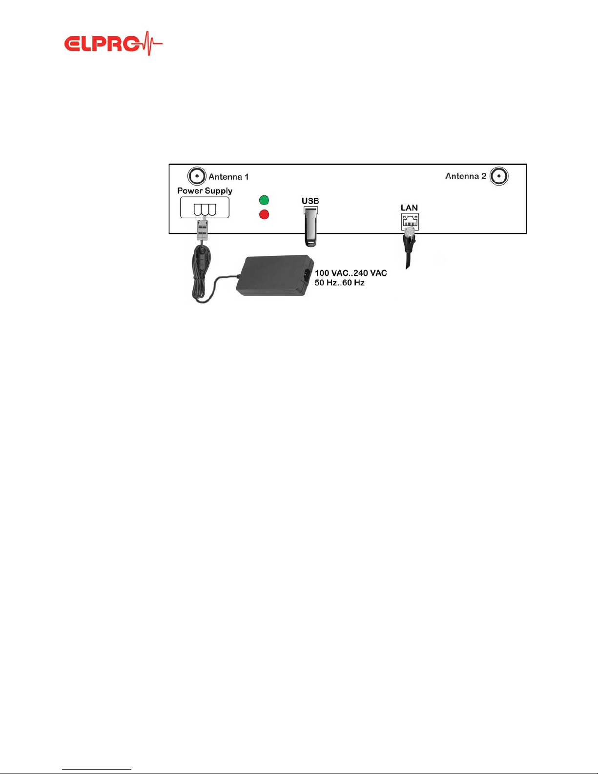
Power supply External power supply unit
Follow the safety and application instructions for the power supply unit. Only
operate the device using the supplied power supply unit. Use of an incorrect
power supply unit may cause damage to the device. Always replace defective
or damaged power supply units.
UPS batteries Material safety data sheets in compliance with EEC Directive 93/112/EC and
shipment recommendations are available from ELPRO. Do not subject batteries
to mechanical stress or damage them. Leaking battery fluid is highly corrosive
and may generate severe heat or may cause a fire if it comes in contact with
moisture.
Environmental conditions Application: 0°C to 40°C
Temperatures above 100°C may damage the battery.
Application: 10% RH to 95% RH, non-condensing
Protection class: IP20, ingress of water / humidity may cause damage to
the device.
IR radiation (heat) and superheated steam may damage the surface
coating of the casing.
No guarantee can be given if functions exceed the specified threshold
range.
MAKE SURE THE ECOLOG-PRO BASE IS AT ROOM TEMPERA-
TURE BEFORE INITIAL STARTUP.
Casing To clean the modules, use a slightly moist cloth. Never use thinner,
gasoline, alcohol, or any other cleaning agents since they may damage
the casing.
Installed applications elproMONITOR
Configuring and monitoring data loggers.
SM3031Db
elproUSER
elproMONITOR user management.
SU6031D
elproEVENT
Audit trail which complies with the cGxP Environment requirements of
elproMONITOR.
SV6031D
ECOLOG-PRO Base Maintenance
Software for initial startup, setting, and maintenance of the
ECOLOG-PRO Base
3 ECOLOG-PRO Base Maintenance
elproMONITOR-WebAccess
Service on the server for creating text files that are required for the web
application elproLOG MONITOR-WebAccess. This optional web appli-
cation must be installed on a separate web server.

Document: EP6002Eb
INITIAL STARTUP
6 - EN
2 Initial Startup
2.1 ECOLOG-PRO Base
Casing underside, position of sockets, indicators, and antennas
Connections Depending on the operating mode, the ECOLOG-PRO Base is connected only to the power
supply unit or additionally to a network cable.
Optionally, an external data memory drive can be connected to the USB port provided (USB
3.0). This connection is also used for configuration, updates, and service work by ELPRO.
Note on initial startup The sections: 2.1 ECOLOG-PRO Base to 2.3 WLAN Connection are also described in the
document: EP6401A which is supplied along with the ECOLOG-PRO Base.
LEDs and connections Confirmation tone sequence
LED, green Power on Start 1 long acoustic signal
LED, red Hard disk active Success 2 short acoustic signals
Power supply Socket for external power supply
unit
Error 2 long acoustic signals
Antenna 1, 2 WLAN antenna connection
USB USB port for data exchange
and initialization.
Drive letter G
LAN Gigabit Ethernet LAN port

Document: EP6002Eb
INITIAL STARTUP
7 - EN
2.2 LAN Connection
Step 1
Step 2
Step 3
Step 4
Step 5
Step 6
2.3 WLAN Connection
Step 1
Step 2
Step 3
The PC used for configuration must be in the same network as the ECOLOG-PRO
Base.
Connect the cable and power supply
unit.
ECOLOG-PRO Base starts.
Start process. Wait for the confirmation tone indicating ready
(operating system started).
Plug in the USB stick. Wait for the confirmation tone (Success, Error).
Remove the USB stick.
Plug the USB stick in the PC. File: Open the file NetworkConfig.txt.
Use the IP address below the line “Desc: Intel(R)
Ethernet Connection (2) I219-V" to log in to the
ECOLOG-PRO Base.
Open your web browser and run
initialization.
2.4 Initialization
Path: http://192.168.253.106/Maintenance
Create the file WlanConfig.txt on a USB stick.
Enter the SSID name in the first line and the
WLAN password in the second line.
If a password is not required for the WLAN, leave
this line blank.
Encryption is set to WPA2.
Connect the power supply unit. ECOLOG-PRO Base starts.
Plug in the USB stick. Wait for the confirmation tone (Success, Error).

Document: EP6002Eb
INITIAL STARTUP
8 - EN
Step 4
Step 5
Step 6
2.4 Initialization
Login
Language
Remove the USB stick.
Plug the USB stick in the PC. File: Open the file NetworkConfig.txt.
Use the IP address below the line “Desc: Realtek
8821AE Wireless LAN 802.11ac PCI-E NIC" to
log in to the ECOLOG-PRO Base.
Open the web browser and run
initialization.
2.4 Initialization
Path: http://192.168.253.106/Maintenance
At initial startup, the ECOLOG-PRO Base is initialized by the configuration wizard
on the ECOLOG-PRO Base. To carry out this configuration, make sure the LAN
or WLAN is connected to the ECOLOG-PRO Base.
Log in to the ECOLOG-PRO Base using the
username and password set on delivery.
- Username: admin
- Password: elpro
Select the initialization language by left-clicking
the country flag of your choice.

Document: EP6002Eb
INITIAL STARTUP
9 - EN
Displays
Carry out the five initialization steps in the order listed below. You can change all the con-
figurations on the dashboard at a later date, including the administrator password and the
computer name.
You can only change the administrator password after the initial setup in elproUSER.
Step 1
Step 2
System
Step 3
Network
Only the highlighted part of the configuration
wizard is displayed in the following procedure.
Next, Back Skip forward or backward in the configuration
wizard.
Administration
IMPORTANT: If you forget this
password, ELPRO can reset it.
6 Recovery
The password must consist of at
least 8 characters and comprise
1 uppercase letter, 1 lowercase
letter, and 1 numeral. Special
characters are not permitted.
Define the computer name. Spe-
cial characters are not permitted.
Select the language for events
(audit trail entries). The only lan-
guages presently available are
German and English.
Select the connection type to the
network.
- DHCP
- Static

Document: EP6002Eb
INITIAL STARTUP
10 - EN
Step 4
Region
Step 5
Summary
Finish
Finish
Select the national settings for
date and time.
End your input for the current time
with: DONE.
Check your settings
and end the initializa-
tion.
IMPORTANT: YOU
CANNOT RESTART
THE WIZARD
AFTER YOU END
THE INITIALIZA-
TION.
The present configuration is saved on the
ECOLOG-PRO Base.

Document: EP6002Eb
INITIAL STARTUP
11 - EN
Restart • Log in to the ECOLOG-PRO Base using the username and
password set on delivery.
• The application ECOLOG-PRO Base Maintenance in the
dashboard view starts after login.
3 ECOLOG-PRO Base Maintenance

Document: EP6002Eb
ECOLOG-PRO BASE MAINTENANCE
12 - EN
3 ECOLOG-PRO Base Maintenance
Start ECOLOG-PRO
Base Maintenance
The ECOLOG-PRO Base Maintenance application can start as follows:
1. Enter the IP address of the ECOLOG-PRO Base with the extension: /Maintenance in a
web browser.
Example: http://xxxx.yyyy.zzzz/Maintenance → Login ECOLOG-PRO Base Mainte-
nance
2. From the elproMONITOR application
Menu: BASE → Login ECOLOG-PRO Base Maintenance
elproMONITOR
REPORT Generates a report containing the present settings of the ECOLOG-PRO Base.
3.7 Example of a Configuration Report
SAVE Saves all settings and exits the configuration.
CANCEL Cancels the configuration without saving the changes.
3.1 Region
SETTINGS - Region
Carry out the following changes to the configuration using the ECOLOG-PRO
Base Maintenance application.

Document: EP6002Eb
ECOLOG-PRO BASE MAINTENANCE
13 - EN
• Timezone
Local timezone for the ECOLOG-PRO Base
• Decimal Separator
• Date format
• First Day of the Week
3.2 Network
SETTINGS - Network
• Type
• SSID, Password
SSID and Password of the WLAN used.
• Folder
Path to the network drive used as backup drive, for example.
Activate the selection box and enter the data required.
. or , Select the option of either period or comma for display.
DD.MM.YYYY
DD/MM/YYYY
MM/DD/YYYY
YYYY-MM-DD
DD.MMM.YYYY
MMM/DD/YYYY
Select the option to display the date.
24 Hour Time FormatSelect the time display option between 12 hours and 24 hours.
Sunday
Monday
Select the option for the start of the week.
DHCP
Static
Select the option to assign the IP address.

Document: EP6002Eb
ECOLOG-PRO BASE MAINTENANCE
14 - EN
TEST CONNECTION Tests the connection to the network drive in the local network (LAN) of the
ECOLOG-PRO Base.
Credentials Required Activate if credentials are required for the network drive.
3.3 Database
SETTINGS - Database
Daily backup active Starts automatically a daily backup of the databases to the selected drive.
• Select the backup destination
BACKUP NOW The database backup is started manually to the drive specified.
A database can only be restored from a backup by ELPRO.
3.4 Update
SETTINGS - Update
USB
Network
A database backup can be sent to a medium (USB stick or hard disk)
connected to a local USB port (drive letter G) or to a drive in the local
network (LAN).

Document: EP6002Eb
ECOLOG-PRO BASE MAINTENANCE
15 - EN
• Select the update file
List containing the files to update the ECOLOG-PRO Base.
UPDATE Starts the update of the ECOLOG-PRO Base.
3.5 System
SETTINGS - System
• Language for audit trail
The language selected is used for events (audit trail entries).
xxxxxxx Settings for comments and acknowledging warnings and alarms.
• System Time
Manual resetting of the time for the ECOLOG-PRO Base.
• If the ECOLOG-PRO Base is in a network with web access, the time is synchronized
automatically to the Windows time server.

Document: EP6002Eb
ECOLOG-PRO BASE MAINTENANCE
16 - EN
3.6 WebAccess
Settings - WebAccess
• WebAccess Active
Tick this checkbox to start or stop the elproMONITOR WebAccess service.
• Interval
Interval Dropdown menu the select the interval for updating data entries.
• The selection options are 1, 5, or 10 minutes.
Maximum 2000 entries corresponding to 2000 measured values per sensor can be
written to the logger protocol.
• Number of entries for alarm protocol
Maximum 500 entries corresponding to 500 measured values per sensor can be written
to the alarm protocol.
• Alarm/Group/Logger Directory
These three boxes define the names of the directories in each case. The 3 directories
are created as subdirectories on the network drive specified.
• The alarm protocol is created in the alarm directory as a CSV file.
• A CSV file is created in the group directory for each sensor group created.
• A CSV file is created in the logger directory for every ECOLOG-NET logger and for
every ECOLOG-PRO measurement module (4PT, 4MA, 2TH).
A CVS file is created for each “Operation mode” (Standard, Time Monitor, and Edge
Counter) for the ECOLOG-PRO 4DI measurement module. Please refer to the opera-
tion manual of the elproMONITOR software for details on the various modes.
SM3031E elproMONITOR operation manual

Document: EP6002Eb
ECOLOG-PRO BASE MAINTENANCE
17 - EN
3.7 Example of a Configuration Report
Configuration report - pages 1 and 2
The configuration report is only available in English at present.

Document: EP6002Eb
OPERATING MODES
18 - EN
4 Operating Modes
4.1 Connection via SWITCH (operated autonomously)
Ethernet cable
- Connection between the individual modules
by an external switch
- ECOLOG-PRO Base is connected to the
switch by LAN.
- The following I/O modules can be connected
by LAN:
- ECOLOG-PRO LBR
- ECOLOG-NET LR8
- ECOLOG-NET LP4
- ECOLOG-NET LA8
Application example - Using the system in an autonomous network
- All components are connected to a switch.
- No connection to the web
Conditions Autonomous as stand-alone solution.
Security No security against malware transferred directly when the USB port to the
ECOLOG-PRO Base is used. The ECOLOG-PRO Base has no WINDOWS
Defender and carries out no automatic WINDOWS updates.

Document: EP6002Eb
OPERATING MODES
19 - EN
4.2 Integration in Customer Network
Higher-level network
- ECOLOG-PRO Base is integrated in the
customer network by LAN (or WLAN).
- The following I/O modules can be connected
by LAN:
- ECOLOG-PRO LBR
- ECOLOG-NET LR8
- ECOLOG-NET LP4
- ECOLOG-NET LA8
Application example - Using the system in the customer network
- All components are connected over the customer LAN (Local Area
Network) or WAN (Wide Area Network).
- A connection to the web is possible (required for remote support from
ELPRO using TeamViewer).
Conditions The network is the responsibility of the customer.
Requirements:
- Permanent accessibility of components in the network
- Response time: <100 ms
Security The ECOLOG-PRO Base has no firewall of its own and must therefore
receive its external protection from the customer network.

Document: EP6002Eb
POWER SUPPLY UNIT
20 - EN
5 Power Supply Unit
Power supply unit
The power supply unit is delivered without a
country-specific power cord for the AC input.
A power failure of the ECOLOG-PRO Base is
bridged by the UPS integrated in the ECOLOG-PRO
Base. The UPS bridges for 10 seconds and ensures
a controlled switch-off of the ECOLOG-PRO Base
without data loss.
Power supply unit contained in the scope of supply of the
ECOLOG-PRO Base
Input voltage 100 VAC to 240 VAC, 50 Hz to 60 Hz
Output voltage 19 VDC ±5%
Output current max. 6320 mA
Dimensions 90 x 55 x 34 mm
Connection cable
length
1500 mm
Content of package Power supply unit with connection cable and plug for connection to the ECOLOG-PRO
Base.
Table of contents
Other ELPRO Measuring Instrument manuals