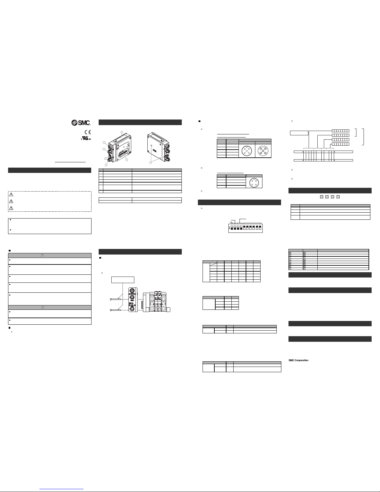
Summary of Produ t element
<EX260-SDN1/-SDN2/-SDN3/-SDN4>
Installation
Swit h setting
Set the DeviceNetTM node address (MAC ID), DeviceNetTM communication speed and
fail safe mode of the SI unit with 10-element switch.
Communication speed
Address
HW/SW
HOLD/CLEAR
9 107 85 63 41 2
ON
Fieldbus interface connector (BUS OUT)
Element Description
DeviceNetTMconnection (M12 5-pole socket, A-coded)
Fieldbus interface connector (BUS IN) DeviceNetTM connection (M12 5-pole plug, A-coded)
Ground terminal Functional earth (M3 screw)
Output connector Output signal interface for valve manifold
1
No.
2
4
5
Accessories
ED and switch Bus status−specific and SI unit−specific EDs
Switches for setting of node address and operating mode
Mounting hole
Mounting hole for connection to the valve manifold
6
7
Power supply connector
Power supply with load voltage for valves
(M12 4-pole plug, A-coded) 3
General instru tions on installation and maintenan e
Connect valve manifold to the SI unit.
Connectable valve manifolds are same as for EX250 series SI unit.
Refer to the EX250 series valve manifold section in the valve catalogue for valve
manifold dimension.
Power supply onne tor layout
Ground terminal
Connect the ground terminal to the ground.
Resistance to ground should be 100 ohms or less.
Setting
MAC ID
Switch No. No.6No.5 No.8No.7 No.10No.9
Note: Each output can be set under individual conditions through the network.
M3 hexagon screw
Tightening torque 0.6 Nm
Valve manifold
*: Thread size: M3×30
Replacement of the SI unit
•Remove the M3 hexagon screw from the SI unit and release the SI unit from the
valve manifold.
•Replace the SI unit.
•Tighten the screws with the specified tightening torque. (0.6 Nm)
Precautions for maintenance
•Be sure to switch off the power.
•Check there is no foreign matter inside the SI unit.
•Check there is no damage and no foreign matter being stuck to the gasket.
•Be sure to tighten the screw with the specified torque.
If the SI unit is not assembled properly, inside PCBs may be damaged or liquid and/or
dust may enter into the unit.
Output number assignment
Output number starts at zero and refers to the solenoid position on the manifold.
Bit: 7 0
Bit: 7 0
Bit: 7 0
Bit: 7 0
0
1
246
357
8
9
16
17
30
31
28
29
64
・・・・・・
・・・
・・・
・・・・・・
64
13571 1 57
Output No.
Output No.
Bit No.
Bit No.
→
Valve manifold
Solenoid on side A
Solenoid on side B
Side D
0: Solenoid valve: OFF
1: Solenoid valve: ON
Byte
0 Offset
Byte
1 Offset
Byte
2 Offset
Byte
3 Offset
(SI unit side)
200
0
16 outputs
type
32 outputs
type
PWR (V)
ED Description
Turns ON in green when load voltage for the valve is supplied
Turns OFF when load voltage for the valve is not supplied or outside tolerance range (19V or less)
PWR Turns ON in green when network power is supplied
NS Network status (See the table below for details)
MS SI unit status (See the table below for details)
Green On
MS status Description
On-line state, The device has connections in the established state.
Green On Off-line state, The device has not completed the Dup_MAC_ID test yet
Green On On-line state, The device has no connections in the established state
Green On
NS status
Off
Green flashing
Red On Off-line state, Watchdog timer error
Red flashing Wrong switch setting, Parameter writing error
Green On Bus-off state, Duplicate MAC ID
Off
Off
Red On
Troubleshooting
The technical document states detail troubleshooting information can be found on
the SMC website (UR http://www.smcworld.com)
Spe ifi ations
Connected load: 24 VDC Solenoid valve with light and surge voltage suppressor of 1.5 W
or less (manufactured by SMC)
Current consumption of power supply for SI unit operation: 0.1 A max.
Ambient temperature for operation: -10 to 50 ℃
Ambient temperature for storage: -20 to 60 ℃
Pollution degree 2: (U 508)
The technical document states detail specification information can be found on the
SMC website (UR http://www.smcworld.com)
Akihabara UDX 15F, 4-14-1, Sotokanda, Chiyoda-ku, Tokyo 101-0021, JAPAN
Phone: +81 3-5207-8249 Fax: +81 3-5298-5362
URL http://www.smcworld.com
Outline Dimensions
The technical document states detail outline dimensions information can be found
on the SMC website (UR http://www.smcworld.com)
A essories
The technical document states detail accessories information can be found on the
SMC website (UR http://www.smcworld.com)
−
Designation Contact layout
+24 V for solenoid valve
−
1
No.
2
3
0 V for solenoid valve4
PWR: M12 4-pole Plug A-coded
Address setting (swit h No. 5 to 10)
Set the DeviceNetTMnode address (MAC ID) in binary coded. Address range is 0 to 63.
Note: Factory default setting is 63.
16
324
812
00 0
0000
00 00 101
00 00 012
:: :: :::
11 11 0162
11 11 1163
0: OFF, 1: ON
Communi ation speed setting (swit h No. 3 to 4)
Set the DeviceNetTM communication speed in binary coded.
Note: Factory default setting is 125kbps.
Communication
speed
Switch No. No.4No.3
00
10250 kbps
01500 kbps
11-
0: OFF, 1: ON
125 kbps
HOLD/CLEAR setting (swit h No.2)
Set the reaction of outputs to the communication error
(All outputs will be set under the same conditions)
Note: Factory default setting is C EAR
HO D/C EAR
Switch No. Description
No.2
0
Hold last state right before communication error1
HO D
C EAR Clear all outputs
HW/SW mode setting (swit h No.1)
Set the setting method, either by local or by network, for the setting of address and
speed.
ocal setting: Hardware mode (Hereinafter referred to as “HW mode”)
Network setting: Software mode (Hereinafter referred to as “SW mode”)
Note: Factory default setting is "HW mode" setting
HW/SW
Switch No. Description
No.1
0
Set the address and speed over the DeviceNetTM network
(Switch setting is invalid)
1
SW
HW Set the address and speed in a local with switch on the SI unit
BUS OUT: M12 5-pole Socket A-coded
Conne ting ables
Select the appropriate cables to fit with the connectors mounted on the SI unit.
DRAIN
Designation Contact layout
BUS IN
V+
V-
CAN_
1
No.
2
3
5
CAN_H
4
BUS OUT
BUS IN: M12 5-pole Plug A-coded
Setting over the Devi eNetTM network
The technical document states detail setting over the network information can be
found on the SMC website (UR http://www.smcworld.com)
Green On I/O Connection is in the Timed-Out state
Off No network power present
Red flashing
Off
0: OFF, 1: ON
0: OFF, 1: ON
Diagnosti information
The technical document states detail diagnostic information can be found on the
SMC website (UR http://www.smcworld.com)
Hexagon socket head cap screw 2pcs. M3x30 screw for connection to the valve manifold
Seal cap 1pc. seal cap for unused fieldbus interface connector (BUS OUT)
Assembly and disassembly of the SI unit
Note: Be sure to switch off the power supply when set on the switch.
Note: If you are concerned about disruption of "downstream" devices whilst replacing the SI unit,
use a DeviceNetTM tap rather than making connections to the BUS OUT connector.
Fieldbus interfa e onne tor layout
NOTE
When conformity to U is necessary the SI unit must be used with a U 1310
Class2 power supply.
Safety Instru tions
Do not operate the produ t outside of the spe ifi ations.
Do not use for flammable or harmful fluids.
Fire, malfunction, or damage to the product can result.
Verify the specifications before use.
Do not disassemble, modify (in luding hanging the printed ir uit board) or repair.
An injury or failure can result.
Do not operate in an atmosphere ontaining flammable or explosive gases.
Fire or an explosion can result.
This product is not designed to be explosion proof.
If using the produ t in an interlo king ir uit:
•Provide a double interlocking system, for example a mechanical system.
•Check the product regularly for proper operation.
Otherwise malfunction can result, causing an accident.
The following instru tions must be followed during maintenan e:
•Turn off the power supply.
•Stop the air supply, exhaust the residual pressure and verify that the air is released before performing mainte-
nance.
Otherwise an injury can result.
Provide grounding to assure the safety and noise resistan e of the Fieldbus system.
Individual grounding should be provided close to the product with a short cable.
Fieldbus devi e
Operation Manual
EX260 Series for DeviceNetTM
Thank you for purchasing an SMC EX260 Series Fieldbus device (Hereinafter
referred to as "SI unit" ).
Please read this manual carefully before operating the product and make sure you
understand its capabilities and limitations.
Please keep this manual handy for future reference.
To obtain more detailed information about operating this product,
please refer to the SMC website (UR http://www.smcworld.com) or
contact SMC directly.
Safety Instru tions
These safety instructions are intended to prevent hazardous situations and/or
equipment damage.
These instructions indicate the level of potential hazard with the labels of
"Caution", " Warning" or "Danger". They are all important notes for safety and
must be followed in addition to International standards (ISO/IEC), Japan Industrial
Standards (JIS) and other safety regulations.
Warning
Caution
After maintenan e is omplete, perform appropriate fun tional inspe tions.
Stop operation if the equipment does not function properly.
Safety cannot be assured in the case of unexpected malfunction.
CAUTION indicates a hazard with a low level of risk which, if
not avoided, could result in minor or moderate injury.
Caution:
Warning:
Danger:
WARNING indicates a hazard with a medium level of risk
which, if not avoided, could result in death or serious injury.
DANGER indicates a hazard with a high level of risk which, if
not avoided, will result in death or serious injury.
Operator
This operation manual is intended for those who have knowledge of machinery
using pneumatic equipment, and have sufficient knowledge of assembly,
operation and maintenace of such equipment. Only those persons are allowed
to perform assembly, operation and maintenance.
Read and understand this operation manual carefully before assembling,
operating or providing maintenance to the product.
Note: Specifications are subject to change without prior notice and any obligation on the part of the manufacturer.
DeviceNetTM is a trademark of ODVA.
© 2010 SMC Corporation All Rights Reserved


