Elster Instromet TRZ User manual

Instruction Manual
Turbine Gas Meter and Quantometers
Type TRZ TRZ2 TRZ-IFS Q

Contents
1. Intended use and field of application ....................................................................... 3
2. Technical data.......................................................................................................... 4
3. Operating location.................................................................................................... 5
4. Staff.......................................................................................................................... 6
5. Legal declarations.................................................................................................... 6
6. Installation / connection............................................................................................ 6
7. Pulse generators...................................................................................................... 7
8. Pressure test point ................................................................................................... 7
9. Temperature test points ........................................................................................... 8
10. Counter versions...................................................................................................... 9
11. Absolut ENCODER .................................................................................................. 9
12. Commissioning......................................................................................................... 10
13. Maintenance and lubrication .................................................................................... 11
14. Care and cleaning .................................................................................................... 11
15. Recycling and environmental protection .................................................................. 11
16. Annex A
ATEX approvals ....................................................................................................... 12
17. Annex B
Plastics used ............................................................................................................ 13
All rights reserved. Subject to technical modification. Page 2 of 13

1. Intended use and field of application
This product is intended
for calibratable volumetric metering using turbine gas meters and for
non-calibratable volumetric metering using quantometers of
- flammable gases: natural gas/town gas/propane/butane/hydrogen
- non-flammable gases: air/nitrogen/inert gases
- suitable for use in potentially explosive atmospheres of Category 2 (Zone 1)
of Class EX II 2 G c IIC
Other fields of application / media on request
This product is not intended
- for metering of aggressive gases, e.g. biologically produced methane or sewage gases,
oxygen, acetylene
Turbine gas meter with volume corrector
1 Meter housing
2 Measuring cartridge
3 Counter head
4 HF pulse generator
5 LF pulse generator
6 Pressure test point with three-way
cock
7 Temperature test point
8 Electronic volume corrector
Please contact your ELSTER After-Sales Service for assistance in commissioning,
maintenance and installation of encoders, pulse generators and volume correctors for
instance.
All rights reserved. Subject to technical modification. Page 3 of 13

2. Technical data
- Turbine gas meters and quantometers in accordance with DIN EN 12261
Type TRZ / TRZ-IFS TRZ2 Q
Size G 65 – G 16000 G 100 – G 1000 Q 65 – Q 16000
Nominal
diameter DN 50 – DN 600 DN 80 – DN 150
Rated
pressure PN 10 – 100 / ANSI 150 – 600
Housing
material Spheroidal graphite cast iron, cast steel,
welded steel
Temperature
ranges
- Gas
- Ambient
-20°C to +60°C
-20°C to +70°C
-10°C to +60°C
-20°C to +70°C
- Pulse generators
LF pulse generator E1 (reed contact) HF pulse generator (in accordance with
DIN EN 50227)
Umax = 24 V Urated = 8 V DC
Imax = 50 mA I ≥2.1 mA (exposed) I ≤1.2 mA (covered)
Pmax = 0.25 VA U < 5.9 V (exposed) U > 6.8 V (covered)
Ri= 100 Ω(series resistor) Ri= 1 kΩ
- Absolut ENCODER S1
Encoder S1
Counter
Number of digit rollers 8
Temperature range -20°C to +60°C
Safety class IP 67
NAMUR (II 2 G EEx ia IIC T4) or
SCR (II 2 G EEx ib IIB T4) or
Interfaces
ATEX approval M-Bus
Meter types TRZ, Q all sizes
LF pulse generator Optional or retrofittable INS-10, INS-11,
INS-12
Umax = 24 V, Imax = 50 mA, Pmax = 0.25 VA,
Ri= 100 Ω(series resistor)
All rights reserved. Subject to technical modification. Page 4 of 13

3. Operating location
The length of the inlet and outlet section must be at least twice the nominal diameter
for reasons relating to measuring accuracy.
The inlet section must be designed as a straight pipe section with the same nominal
diameter as the meter.
Flow
disturbanc
es
resulting
from:
Typical inlet
sections
Pipe sections
installed at a
distance of
2D upstream
of the meter
inlet
TRZ
PTB approval
symbol
TRZ2 / TRZ-IFS
PTB approval
symbol
Q
Minor
disturbanc
es
- single
manifolds
- twin
manifolds
- diffuser
and
- contractor
s
L ≥2D
DN 50 – DN 150
No flow conditioner
DN 200 – DN 600
Flow conditioner
(e.g. BLN 1)
No flow conditioner
if L ≥5D
L ≥2D
No flow
conditioner
L ≥5D
Major
disturbanc
es
- Pressure
regulators
for gas
- Other
restrictor
devices
L ≥2D
Flow conditioner
(e.g. BLN 1)
L ≥2D
No flow
conditioner
L ≥5D
Flow
conditioner
recommended
If you ..
- wish to mix in odorisation agents or
- use solenoid valves,
please always fit them only downstream of the meter. Otherwise, the device may be
damaged.
The flow through the meter must be free of vibration/pulsation in order to avoid
measuring errors.
Compliance with the specified operating and ambient conditions as indicated on the
type label is absolutely essential for safe operation of the meter.
The gas may not contain suspended particles > 50 µm. In addition, the gas must be
dry. Otherwise, the meter may be damaged.
In the case of new installations, we recommend temporarily installing a cone strainer
(mesh size 250 µm) to protect the meter. The strainer should be removed after
approximately 4 weeks.
All rights reserved. Subject to technical modification. Page 5 of 13
4. Staff
These Instructions are aimed at staff who have adequate specialist and technical
knowledge (in Germany, for instance, in accordance with DVGW Codes of Practice 492
and 495 or comparable technical regulations) on the basis of their training and experience
in the sector of energy and gas distribution.
5. Legal declarations
- Declaration of Conformity – see enclosure
- Period of validity of calibration – this is based on the regulations of the country
concerned, in which the turbine gas meter will be used.
- The calibration of turbine gas meters is only valid for the period of validity of calibration.
Once this has elapsed, turbine gas meters may no longer be used for purposes which
are subject to obligatory calibration.
- The period of validity of calibration can be extended if an official random sample shows
that the measuring instruments used provide correct results.
6. Installation / connection
Warning! Never clean the plastic cover of the counter with a dry cloth owing to the risk
of explosion resulting from electrostatic discharge! Please only ever use an
adequately moistened cloth!
Before installation please ensure:
- that the protective caps and/or plastic sheeting is or are removed,
- that the meter and accessories have been inspected for transport damage and
- that the accessories have been checked for completeness (e.g. plug connectors, oil for
initial filling).
You will require the following items for installation
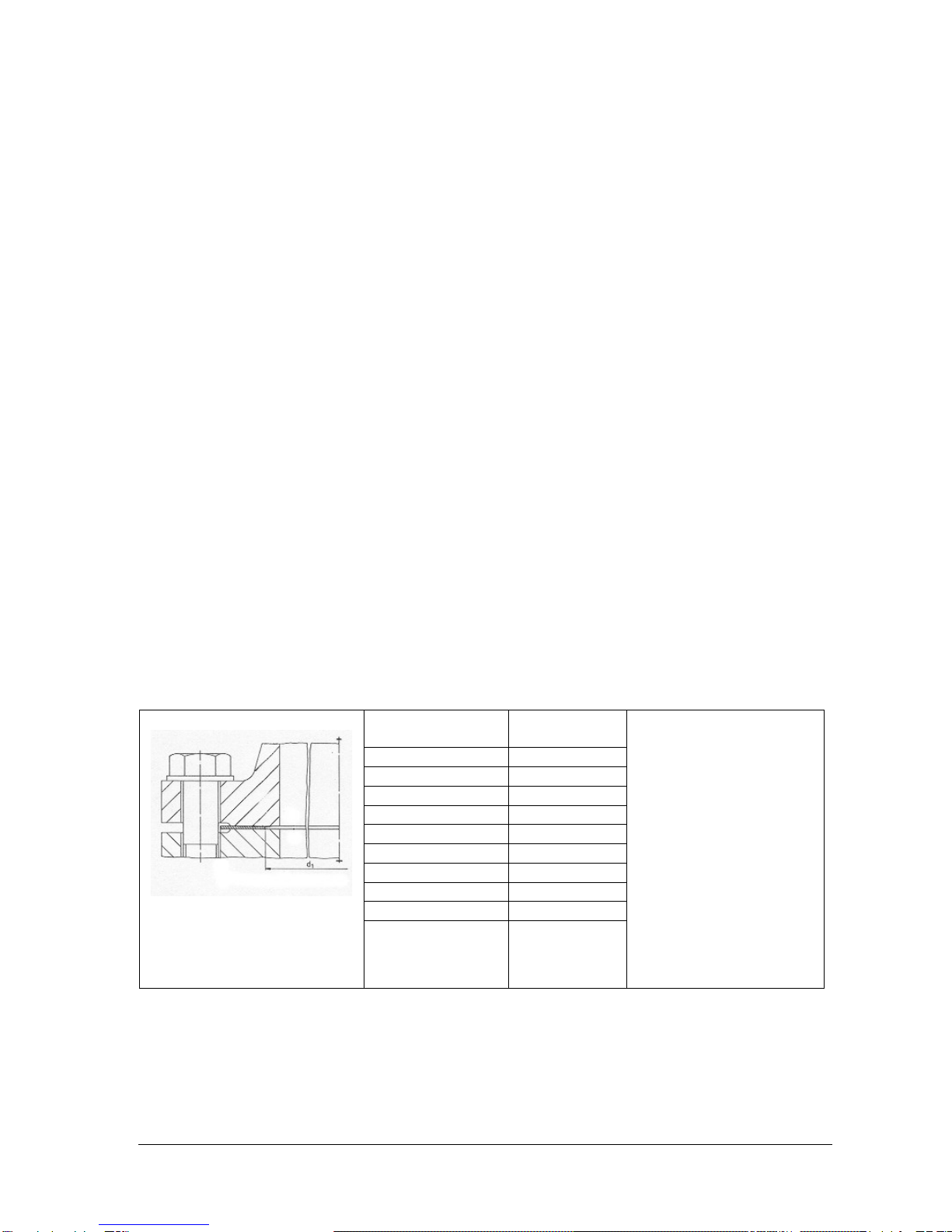
- Suitable seals/gaskets for the relevant gases, e.g. in accordance with the following
table:
DN d1
(mm)
50 62
80 100
100 125
150 178
200 223
250 278
300 334
400 412
500 506
600 600
The following seals
and gaskets,
amongst others,
are suitable:
- Flat seals
- Spiral-wound
gaskets
and
- Grooved seals
and
gaskets
- suitable connection elements in accordance with the tables below for operation:
All rights reserved. Subject to technical modification. Page 6 of 13

Hexagon screws and nuts for flanges in accordance with DIN EN 1092-1
Material / strength class
Screw Nut Operating limits Standards
5.6 5
8.8 8 up to 40 bar
down to -10°C DIN ISO 4014
DIN ISO 4032
CK 35 CK 35 up to 100 bar
down to -10°C
DIN 2510
Stud bolts with continuous thread for flanges
in accordance with ANSI/ASME B 16.5
Material / strength class
Bolt Nut Operating limits Standards
A 193 B6 A 194
Gr. 6 up to 100 bar
down to 0°C
A 193 B7 A 194
Gr. 2H up to 100 bar
down to -50°C
ANSI/ASME B 1.1
Other equivalent materials may also be used.
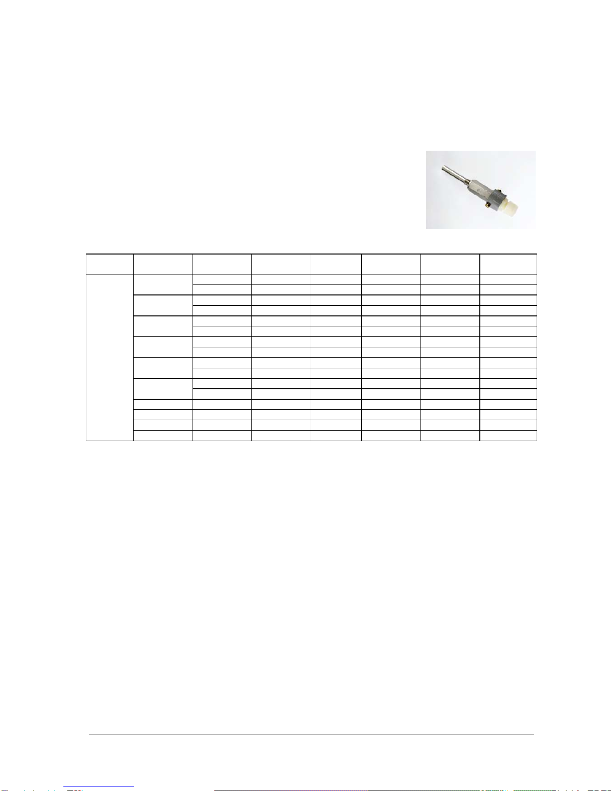
7. Pulse generators
LF pulse generators (Type IN-S) may be plugged onto the side of
the counter cover for volume pulse output to external devices (e.g.
a volume corrector).
Fit the pulse generator (if required) as follows:
- Slide both guides of the IN-S pulse generator into the guide slot
on the counter cover until the guides can be heard to engage
(clicking sound).
- Assign the terminals on the plug in accordance with the pin
assignment on the meter/pulse generator.
- Use a screened cable to the external device.
You can use HF pulse generators for higher frequencies (Types
A1R and A1S) (if available). HF pulse generators are screwed into
the meter housing pressure-tight. However, the connection plug can
be turned.
- Assign the terminals on the plug in accordance with the pin
assignment on the unit.
- Use a screened cable to the external device.
Pulse generators for subsequent installation are also available.
HF pulse generators (Type A1S) can, however, be fitted only by
the After-Sales Service. By contrast, you can connect the plug yourself, as described
above.
Warning! All pulse generators are intrinsically safe and may be connected only to
intrinsically safe circuits if used in potentially explosive atmospheres. The safety
barriers must comply with the requirements of ignition protection EEx ib IIC (see also
Marking in Annex A).
8. Pressure test point
A straight male coupling in accordance with DIN 2353 is pre-fitted on the meter housing for
connection of a pressure sensor for instance.
The pressure test point is marked pmand is designed for connection of d= 6 mm steel
tube in accordance with DIN EN 10305-1 (e.g. steel grade E 235).
All rights reserved. Subject to technical modification. Page 7 of 13
Important: Do not connect the straight male coupling to pipes made of stainless steel or
pipes made of nonferrous materials.
Note: We recommend that you use original Parker-Ermeto pipe unions.
Functional safety and reliability are ensured only if the material combination of the union
component and the pipe are intermatched.
We recommend that you contact our After-Sales Service for conversion work and when
installing additional devices.
9. Temperature test points
You can use a maximum of two temperature sensors for measuring
the gas temperature in the meter housing for the meter sizes listed
in the table below (quantometers cannot be fitted with thermowells in
the meter housing; on TRZ//TRZ-IFS/TRZ2 thermowells are optional
up to nominal diameter DN 200):
Max.
sens
or ø
TRZ
DN Housing
material PN 10/16
EBL PN
25/40
EBL
ANSI 150
EBL ANSI 300
EBL ANSI 600
EBL
GGG - - - - -50 GS - - - - -
GGG 45 - 45 - -80 GS 45 - 45 - -
GGG 50 - 50 - -100
GS 50 - 50 - -
GGG 50 - 50 - -150 GS 50 - 50 - -
GS 58 - 58 - -200 St. - 67 - - -
GS 95 - 95 - -250 St. 160 160 160 160 160
300 St. 160 160 160 160 160
400 St. 160 160 160 160 160
500 St. 160 160 160 160 160
6
mm
600 St. 160 160 160 160 160
GGG -> Spheroidal graphite cast iron; GS -> Cast steel; St. -> Welded steel
EBL -> Rounded installation length of the thermowell in mm
Note that temperature measurement on measuring systems in the open air may be
influenced by the ambient temperature. For this reason, the metering elements outside
the pipe should be adequately insulated against ambient temperature influences. In order
to achieve optimum thermal conduction, you should also always fill the thermowell(s) with a
heat-conductive fluid or paste.
If no temperature test points in the meter housing are scheduled, the temperature must
be measured in the pipe downstream of the turbine gas meter at a distance of up to 3 x
DN, but max. 600 mm away.
All rights reserved. Subject to technical modification. Page 8 of 13
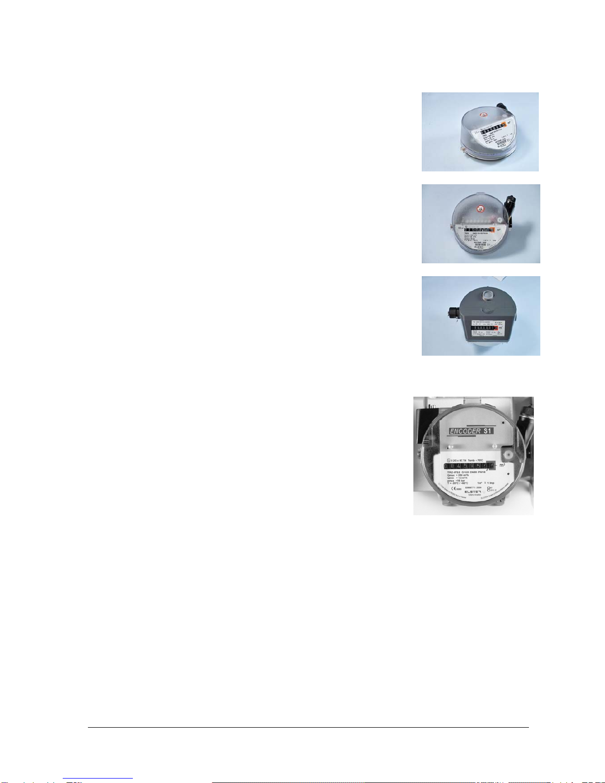
10. Counter versions
The meter can be equipped with various counter versions:
Counter head S1
- This is the standard version with an 8-digit mechanical roller counter
- Provides universal read-off
- Can be rotated up to 355° about its axis
- Suitable for outdoor installation
- Designed for LF pulse generators which can plugged on from the
outside and which can be exchanged on site
Counter head S1V
- This has the same features as counter head S1
- The mechanical roller counter can be read off from the top
Counter head version II
- Provides universal read-off
- Can be rotated up to 355° about its axis
- Features a mechanical index drive pointing upwards in accordance
with EN 12261
- LF pulse generator which is fitted and which cannot be exchanged
on site
IMPORTANT! Version II is not suitable for outdoor installation.
11. Absolut Encoder S1
- This has the same features as counter head S1
- Can be used as main counter on gas meters
- Available as a top-mounted unit (transmitter unit) on meters with
mechanical index drive (counter head version II)
- The encoder is suitable for connection to a series-connected
additional device (volume corrector, datalogger or bus system) in
potentially explosive atmospheres (see table: Technical data). A
device connected to the terminal box must feature at least the
following approval as a related equipment for this:
[EEx ia IIC ] for version with Namur interface
[EEx ib IIC ] for version with SCR interface
Connection of the Absolut ENCODER S1 unit to the mechanical index drive of the
meter
- Connect the connector of the top-mounted unit to the mechanical index drive of counter
head version II.
- Use a locking screw to secure the encoder top-mounted unit against pulling out.
- The locking screw must be lead-sealed for applications requiring mandatory calibration.
- If you wish to synchronise the encoder with the counter reading of your operating meter
after installation or conversion, you will require the Instructions “Encoder synchronisation”
and a special tool. We recommend that you contact our ELSTER After-Sales Service in
such cases.
All rights reserved. Subject to technical modification. Page 9 of 13

Connection of the encoder
- Use only screened cable to connect the encoder and ensure that
the pin assignment is correct (see sticker next to the cover of the
terminal box).
- When connecting the Namur interface, ensure that the 2-wire
connection has the correct polarity. The SCR interface is
independent of the polarity.
Then install the meter
- gas-tight,
- with the supplied accessories,
- only in flow direction (as marked by an arrow on the meter housing),
- only unstressed and
- preferably in horizontal position with the counter at the top.
The permitted installation/operating positions of the meter are specified on the
meter housing in accordance with the designations “H, V or H/V” represented in
accordance with DIN EN 12261. If you have specified the installation or operating
position when ordering, all attachments will have been fitted in accordance with the
installation position ex-works.
If you wish to install the unit vertically at a later point and if an oil pump is present, the
oil pump must also be fitted vertically. If this is not the case, you must turn the oil pump
and its oil connection line and any other attachments, e.g. volume corrector, through 90°
before installing the meter.
We recommend that you contact our After-Sales Service for such conversion work.
- weatherproof.
- When fitting the seals and gaskets, ensure that they are aligned concentrically and do
not project into the flow channel.
12. Commissioning
For meters without oil pump, continue with point “Placing the system into operation”.
Meters with oil pump must be provided with initial lubrication
Before commissioning:
- First open the cover on the oil supply tank.
- Fill the oil supply tank with the supplied oil.
- The oil quantity is sufficient when the oil level reaches around ¾ of the tank volume.
- Operate the oil pump as instructed in Section “Maintenance and lubrication” and
only then close the oil supply tank.
Placing the system into operation
In order not to damage the meter,
- slowly fill the system until operating pressure is reached.
- The pressure rise may not exceed 350 mbar/s. You should also use a bypass line for
filling (recommendation: 12 mm pipe diameter).
- Do no exceed the measuring range even briefly!
- Conduct a tightness test!
Important! Dirt particles, such as welding beads, swarf and other foreign bodies, may be
contained in the gas for a short while after installation.
For this reason, always fit a coarse filter in order to avoid damage to the counter. Do
not forget to remove the coarse filter after approx. 4-6 weeks since, should it become
saturated, this would produce an obstacle to flow.
All rights reserved. Subject to technical modification. Page 10 of 13
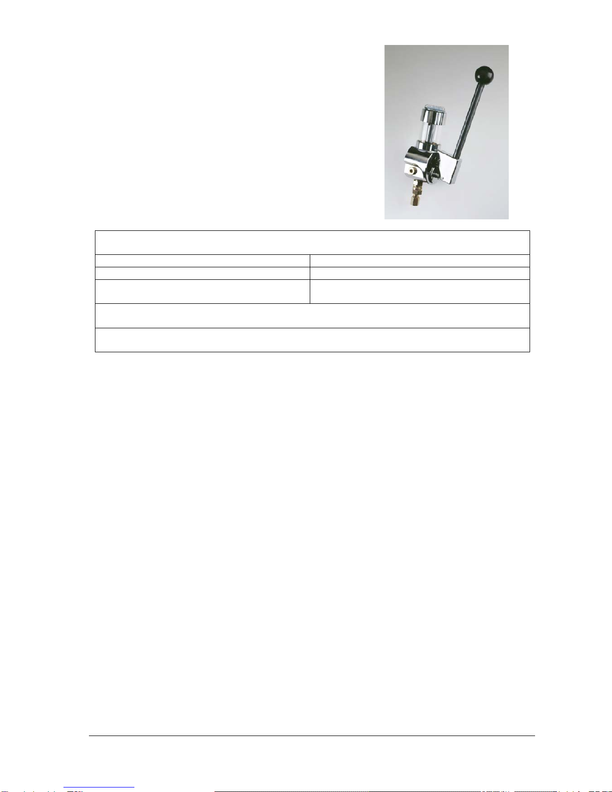
13. Maintenance and lubrication
Meters without oil pump are maintenance-free.
Meters with oil pump must be lubricated.
- You must open the cover of the supply tank before
operating the oil pump’s hand lever.
- Ensure that the supply tank has an adequate quantity of
oil. Use the filter insert in the supply tank when topping
up with oil.
- Operate the oil pump by hand by fully pulling the hand
lever down applying uniform pressure. Note that one pull
corresponds to one stroke of the pump’s piston.
- After operation, you must re-close the supply tank firmly.
Lubrication instructions for turbine gas meters and quantometers
in the case of dry natural gas
DN 50 – DN 200 DN 250 – DN 600
4 – 6 strokes every 3 – 4 months 6 – 10 strokes every 3 – 4 months
10 strokes on commissioning
(initial lubrication) 15 strokes on commissioning
(initial lubrication)
Permitted lubricants: Shell Risella 917
Shell Tellus T 15
Other oils not containing resin and acid, with a viscosity of approx. 30 cStokes at 20°C,
solidification point lower than -30°C, or equivalent oils may be used.
Important!
- Always fill the supply tank with oil in good time to prevent air entering the pipe system.
- Protect the oil pump against the ingress of water by keeping the oil tank firmly closed.
14. Care and cleaning
- Clean off dirt on the meter only with a damp cloth.
Any media gentle on the applicable materials can be used as cleaning media.
- Do not clean the transparent tank of the oil pump with solvent.
15. Recycling and environmental protection
ELSTER has reduced the transport packagings of the measuring instruments to the bare
essentials. Packaging materials are always selected consistently with a view to recycling. The
cardboard items used constitute secondary raw materials for the paperboard and paper industry.
The Instapak®foam packaging items are recyclable and can be reused.
Plastic sheeting and strips/bands are also made of recyclable plastic. At ELSTER, subsequent
recycling and disposal are already elements of the product development process. When
selecting the materials, we allow for reusability of the materials, suitability of materials and
subassemblies for dismantling and separation, and the risks of environmental pollution and
health risks when recycling and dumping on landfill sites. The turbine gas meters and
quantometers mainly consist of metallic materials which can be melted down again in steelworks
and metallurgical plants and which can thus be reused a virtually unlimited number of times. The
plastics used are listed in Annex B so that sorting and separating of the materials for the
purposes of subsequent recycling is possible.
All rights reserved. Subject to technical modification. Page 11 of 13

16. Annex A
The pulse generators used in turbine gas meters have their own ATEX approvals (Ex approvals)
and are marked in accordance with the table below:
Pulse
generator,
Type
Designation of
the sensors EC Type-Examination
Certificate
Directive 94/9/EC
Identification of the
pulse generators
Manufacturer
Reed contacts:
KSK-1A81-0810
KSK-1C97-1020
2322
KSK-1B90U-
BV09904
TÜV 03 ATEX 2123
Ex marking:
II 2 G EEx ia IIC T4
Elster GmbH
55252 Mainz-Kastel
Germany
LF pulse
generators
IN-S..
PCB E1
IN-W11
Wiegand sensor:
Series 2000
magnetic sensor
FTZÚ 04 ATEX 0277
Ex marking:
II 2 G EEx ia IIC T6/T4
TÜV 01 ATEX 1776
Ex marking:
II 2 G EEx ia IIC T4
Premagas s.r.o.
91601 Stará Turá
Slovakia
Elster GmbH
55252 Mainz-Kastel
Germany
Inductive
proximity switch:
N 95000
PTB 01 ATEX 2192
Ex marking:
II 1 G EEx ia IIC T6
IFM Electronic GmbH
45127 Essen
Germany
HF pulse
generators
A1 R, A1 S
Inductive
proximity
switches:
NJ 1,5-10 GM-N
NJ 1,5-8 GM-N
(old version)
(Both versions
with identical
electrical system)
*) NJ 3,5-12 GK-
N (old version)
(Same electr.
system as
NJ 4-12 GK-N)
NJ 1,5-6,5-N
(TRZ DN 50 only)
PTB 00 ATEX 2048 X
Ex marking:
II 1 G EEx ia IIC T6
PTB 00 ATEX 2048 X
Ex marking:
II 2 G EEx ia IIC T6 *
*) NJ 3,5-12 GK-N
Pepperl + Fuchs
GmbH
68307 Mannheim
Germany
Pepperl + Fuchs
GmbH
68307 Mannheim
Germany
All rights reserved. Subject to technical modification. Page 12 of 13

17. Annex B
Plastics used in turbine gas meters and quantometers,
see also point 15 “Recycling and environmental protection”
Plastic parts
Abbreviation Chem. name
Pulse generators PA 6.6 Polyamide
Flow bodies PAMXD6 Polyarylamide
Gears and small parts POM Polyoxymethylene
Counter cover and counter PC Polycarbonate
Counter bottom section PPA Polyphthalamide
Digit rollers PA 12
PPO Polyamide
Polyphenylene oxide
All rights reserved. Subject to technical modification. Page 13 of 13
This manual suits for next models
3
Table of contents
Other Elster Instromet Measuring Instrument manuals


