Elster Instromet RABO G65 User manual

Instromet
RABO®Rotary Gas Meter
Instruction Manual
1. General Information
This manual covers the installation, operation and maintenance
for the Elster Instromet RABO Rotary Meter. Refer to EAM-TB5900
for additional information.
2. Intended Use and Application
Elster RABO meters are suitable for measuring most types of
clean, dry, non-corrosive common gases. They are NOT intended
for use on biogas, sewage gas, oxygen, acetylene or liquids of
any kind. Product life and measurement accuracy can be affected
by contamination in the gas stream. Periodic servicing will prolong
the life and performance of the meter.
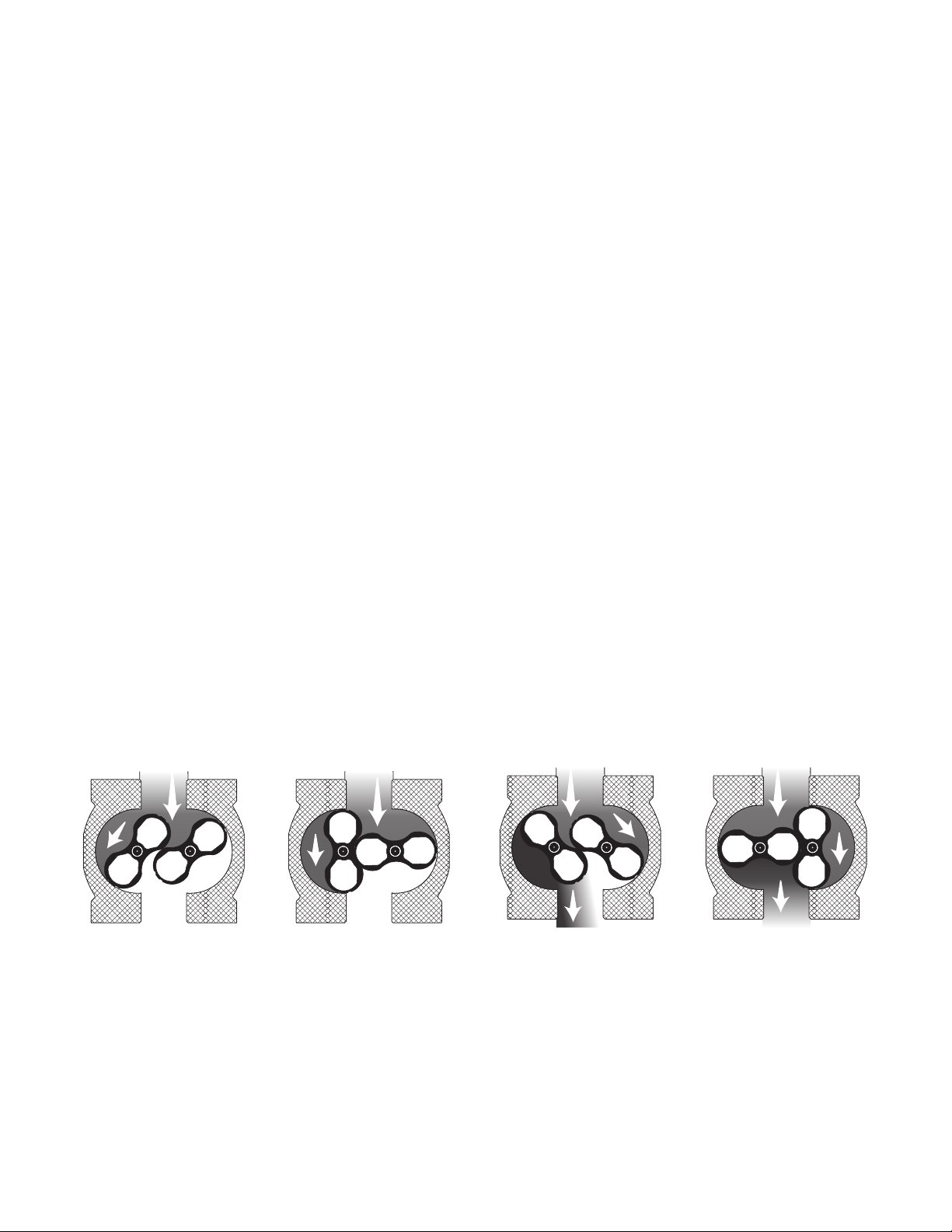
3. Operating Principle
The RABO meter utilizes positive displacement principle of
operation which makes volumetric measurements by displacing
finite volumes of gas. The positive displacement occurs within
a cavity formed between the meter’s internal housing and its
rotating impellers. The counter-rotating “figure-8” impellers [Figure
1] turn as a result of pressure drop across the meter’s inlet and
outlet created as downstream gas is consumed. The rotating
impellers separate the flowing gas into small, finite volumes
and are counted using a mechanical index. The RABO meter
has no wearing parts because precision clearances between
the impellers and meter body are maintained by timing gears,
which are designed to enhance long term accuracy. Combining
adequate filtration and periodic maintenance, a RABO meter will
remain accurate over many years.
As the left impeller rotates
toward the vertical position,
gas enters the cavity created
between the impeller
and the housing.
When the left impeller
reaches the vertical
position, a nite volume
of gas is captured in the
left cavity.
As the impellers continue
to turn, the volume of gas in
the left cavity is discharged.
Simultaneously, gas is
entering the space between
the right impeller and
housing.
After further rotation, the
right impeller becomes
vertical and a nite volume
of gas is captured in the
right cavity.
Figure 1. Operating Principle
Table of Contents
1. General Information 2
2. Intended Use and Application 2
3. Operating Principle 2
4. Receiving, Handling and Storage 3
5. Installation 3
6. Start-up/Commissioning 5
7. Decommissioning and Removal 5
8. Inspection and Maintenance 5
9. Testing 5
10. Technical Data 7
11. Index 8
12. Pulser 10
13. Thermowell 11
14. Auxiliary Equipment Mounting 11
15. Troubleshooting 11
RABO®Rotary Gas Meter
RABO®Rotary Gas Meter 02 Elster Instromet

RABO®Rotary Gas Meter 03 Elster Instromet
4. Receiving, Handling and Storage
Elster RABO meters should be handled with care to protect the
product from damage. If the package shows evidence of damage
through mishandling in transit, you should notify the shipper
immediately, file a claim with the carrier and notify your Elster
supplier.
Damage to internal components may occur without visible
external damage. All new meters should be inspected and
checked for free rotation of the impellers by lightly blowing
into the inlet of the meter. This slight air pressure should
cause the impellers to rotate freely and come to a stop slowly.
NOTICE
DO NOT attempt to make any repairs. Tampering with the
meter may void warranty coverage.
If a meter shows signs of external damage, or if the impellers do
not rotate freely, contact your local Elster sales representative for
return instructions.
Elster RABO meters are supplied with oil in a separate container.
A material safety data sheet (MSDS) is available upon request. DO
NOT put oil in the meter until it is installed and leveled in the gas
piping system. Meters containing oil that are transported or not
installed level may lead to contamination of the measurement
chamber, and will impact accuracy.
Store Elster RABO meters in their original shipping container in a
dry location until installation. If prolonged storage is experienced,
RABO meters should be tested for accuracy before installation.
5. Installation
Elster RABO meters can be installed in horizontal or vertical (top
inlet) piping configurations. Vertical (top inlet) piping is preferred
because it enables the meter to pass contaminants more freely
through the meter. All piping should be properly supported
and aligned to eliminate any strain on the meter, which may cause
the impellers to bind.
Recommended piping practices include a filter or strainer on the
inlet of the meter and non-lubricated isolation valves. A bypass
line will facilitate maintenance and removal of the meter and
provide uninterrupted gas supply.
The meter should not be installed lower than the outlet pipe run.
If it is necessary to install the meter lower than the outlet pipe run,
installation of a drip leg in the outlet piping to capture condensate
is recommended. The meter should never be located at the lowest
point in the system.
A restricting orifice can also be installed at least 4 pipe diameters
downstream of the outlet of the meter to prevent the meter from
flowing excess capacity. Warranty does not cover failures due to
excess flow conditions.
Figure 2. Horizontal installation, side view
HORIZONTAL INSTALLATION
Figure 3. Vertical installation, side view
VERTICAL INSTALLATION
a) Piping Configurations [Figures 2, 3 and 4]
DO NOT weld piping while meter is installed in the
piping system.
If hydro testing, remove the meter from the piping system.
NOTICE
NOTICE
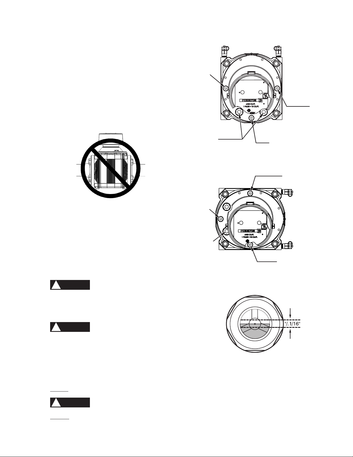
Figure 5. Horizontal installation
Figure 6. Vertical installation
Figure 7. Sight glass
Figure 4. Side view
b) Mounting
1) Always follow your company’s procedures, and
applicable local codes and ordinances.
2) Ensure gas valves are closed.
3) Ensure the upstream piping is clean and free of any
debris.
4) Remove protective caps from meter inlet and outlet prior
to installation.
5) Ensure the impellers turn freely.
6) Ensure the direction of flow using the arrow on the
nameplate.
7) Ensure the meter orientation is correct. Impeller shafts
must be horizontal [Figure 4].
8) Connect the inlet and outlet pipe flanges using
appropriate bolts and gaskets. Inlet and outlet pipe
flanges should be parallel and should not introduce any
bind on the meter body when tightened.
9) Level meter to within 1/16" per foot in all directions and
tighten flange bolts evenly (maximum 80ft-lbs).
c) Adding Oil
!WARNING
Add oil only to the index end of the meter.
1) Ensure gas valves are closed and meter and piping are
depressurized.
!WARNING
Failure to depressurize the meter prior to removing
meter and/or components could result in personal
injury and/or property damage.
2) Remove oil fill plug in the counter end case cover using a
5mm hex key [Figures 5 and 6].
3) Using the supplied syringe and oil, slowly add oil until
it is +/-1/16" of the center of the sight glass [Figure 7].
DO NOT OVERFILL. Only use Shell Morlina lubricating oil.
!WARNING
DO NOT remove any sight glasses. No maintenance
can be performed through these openings.
4) Reinstall the oil fill plug.
OIL
FILL
OIL
LEVEL
SIGHT
GLASS
OIL
DRAIN
OIL
FILL
OIL
FILL
OIL
FILL
OIL
LEVEL
SIGHT
GLASS
OIL
DRAIN
RABO®Rotary Gas Meter 04 Elster Instromet
RABO®Rotary Gas Meter 05 Elster Instromet
7. Decommissioning and Removal
a) Always follow your company’s procedures, and local codes
and ordinances.
b) Slowly open bypass valve.
c) Slowly close the meter’s outlet valve, then the inlet valve.
d) Slowly, completely depressurize the meter piping.
!WARNING
Failure to depressurize the meter prior to removing meter
and/or components could result in personal injury and/or
property damage.
e) Drain oil from the index end case cover and dispose of the oil
in accordance with applicable regulations.
f) If removing the meter from the piping system, loosen flange
bolts. Ensure meter is properly supported before removing
bolts completely.
8. Inspection and Maintenance
It is recommended to inspect Elster RABO meters periodically to
help ensure accurate performance over a long period of time.
Maintenance intervals can be derived from inspection criteria.
Routine inspections should include:
a) Checking to ensure the meter is level in all planes
b) Listening for abnormal sounds in the meter
c) Checking oil level and clarity — oil should be red and clear
d) Checking index movement if gas is flowing
e) Checking for leaks
f) Testing the meter’s differential pressure
Routine maintenance should include:
a) Changing the oil if the color becomes dark
b) Adding oil if the color is red and clear, but below the
recommended level
9. Testing
Elster RABO meters should be tested in accordance with applicable
governing standards. The accuracy of a meter can only be
determined by comparing results to a traceable reference, typically
a sonic nozzle, bell, piston or transfer prover. Accuracy may be
done on site using transfer provers, and typically requires removal
for testing with other technologies.
Differential pressure testing is a method of determining whether
the performance of a rotary meter may have changed over time,
and can be done on site while the meter is operating under
pressure. Baseline data must be captured during initial start-up to
which future data can be compared.
a) Proving
When testing a meter on a prover, the meter temperature,
pressure and volume are necessary inputs for the proving
device. The meter temperature is obtained by a temperature
probe installed near the inlet of the meter. A thermowell
can be installed in the meter run piping or on the meter
itself to facilitate installation of the temperature probe.
The meter pressure should come from the meter differential
pressure taps.
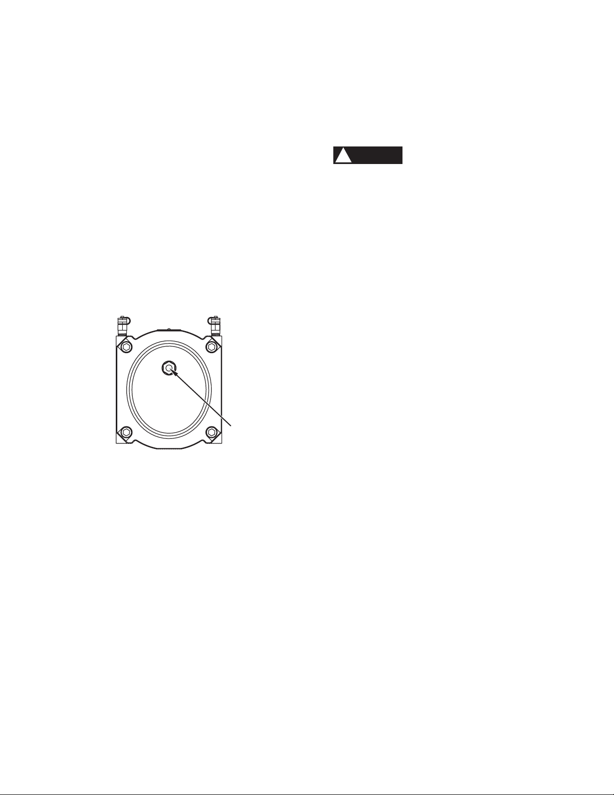
Figure 8. Back of meter
6. Start-up/Commissioning
After the meter has been properly installed, it is important to use
extreme care during start-up to mitigate adverse conditions that
can damage the meter.
a) Ensure that the maximum operating pressure of the meter
will not be exceeded.
b) Always follow your company’s procedures, and local codes
and ordinances.
c) With the meter run’s inlet and outlet valves closed, open the
bypass valve and pressurize the piping system.
d) With the meter outlet valve closed, slowly open the meter
inlet valve not to exceed 5 psig per second until pressure
is equalized throughout the meter piping system. Rapid
pressurization can cause an over-speed condition and
can damage the meter. Damage will not be covered
under warranty. When the meter piping system pressure is
stabilized, open the inlet valve completely.
e) Slowly open the meter’s outlet valve until the meter starts to
operate at low speed. Meter speed can be seen through the
view port located on the back of the meter [Figure 8].
f) Operate the meter at low flow for 1 to 2 minutes to verify
proper operation. If the index does not start registration, or
if you hear knocking or scraping sounds coming from the
meter, stop the flow and follow appropriate decommissioning
procedures before removing the meter from the line.
g) If operation is satisfactory, gradually open the meter’s outlet
valve to the full open position.
h) Slowly close the bypass valve.
i) Check the meter connections for leaks using common
industry practices.
j) Clock the meter (see Index section 11c) to confirm the flow rate
is not exceeding the maximum capacity of the meter.
k) Perform and record the meter’s differential pressure (see
Testing section 9b).
VIEW PORT
(DO NOT REMOVE)

Pete’s Plugs®are provided for simplified pressure connections
[Figure 9]. Typically, when proving a meter, both the meter
pressure and meter differential pressure are used and
recorded. The RABO meter differential pressure ports are not
full bore and most temperature probes will not fit through
into the gas stream. Installing the temperature probe in the
provided thermowell ports is recommended.
b) Differential Pressure Testing
A differential pressure test is not an accuracy test, but it can
be used to gauge the relative performance of the meter.
Rotary meters are made from solid parts, machined to tight
tolerances with close clearance fits, and the energy it takes
to turn the meter is generally used to overcome the friction
of the bearings and other rotating parts. If this friction value
increases, it will take more energy to overcome it. This
additional energy is measured as an increased pressure
drop across the meter.
The increased friction is caused by contamination of the
measuring chamber and/or bearings.
Contamination in the measuring chamber can cause the
meter components to wear against each other. Contamination
in the bearings makes them harder to turn.
Comparing the pressure drop reading when the meter is new
to the reading collected after time allows the performance to
be monitored.
RABO meters are supplied with Pete’s Plugs®installed in the
meter differential pressure ports [Figure 9]. This facilitates
differential meter testing. A differential pressure test is
performed using a differential pressure manometer. The test
is to measure the pressure drop across the meter at a given
flow rate, under known operating conditions at a known date
and time.
The meter differential curve of flow rate vs pressure is not
linear. Testing at multiple flow rates is suggested. It is
preferable to test at 3 rates between 25% and 100% of flow
if possible. Differential pressure tests at flow rates under
25% are hard to interpret because the meter differential
pressure at the lower flow rates is quite small. The error in
measurement is almost as large as the reading itself.
The meter differential pressure is also a function of line
pressure and increases as line pressure increases. Testing
the meter at the same conditions (line pressure and flow
rates) yields comparable data.
A change in the differential pressure indicates a change
in performance. Testing has shown that a 50% increase in
meter differential pressure (at flow rates over 25%), indicates
almost a 1.0% change in meter accuracy.
Baseline data must be captured during initial start-up to
which future data can be compared.
If the differential pressure test shows an increase in the meter
pressure drop at a given flow rate of more than 50% from the
original value (1.5 x original value), then it is recommended
that the meter be removed and serviced.
The frequency of deferential testing is at the discretion of
the user.
Figure 9. Pete’s Plugs®
The meter volume is determined though a device that senses
the meter revolutions. An optical pickup can be used on the
index proving wheel or an index pulser may be used.
On-site proving, performed in-line, also requires connections
that allow air flow through the meter to the prover. This is
accomplished by use of pipe Tees upstream and downstream
of the meter. A bypass loop is recommended for uninterrupted
gas supply to the customer.
While performing an accuracy test, the meter is tested for
a specified volume of gas at each flow rate test point. Poor
repeatability at a given rate may be caused by a test volume
that is too small. It the meter does not repeat within acceptable
limits (0.1%), try increasing the test volume and retesting
the meter. Most companies have developed test plans
that include the volume of gas for each size meter at a
given flow rate. Consult your Elster representative for
applicable volumes.
PETE’S PLUGS®
RABO®Rotary Gas Meter 06 Elster Instromet

RABO®Rotary Gas Meter 07 Elster Instromet
b) Sizing Chart
Using the chart below, select the appropriate meter by using the Maximum Instantaneous Flow Rate (scfh) and the Minimum
Operating Pressure (psig) at any given point in time.
Example: A flow rate of 25,000 scfh and an operating pressure range of 75–100 psig would require a 5.5M meter based on a
75 psig minimum inlet pressure.
Model 3.5M/G65 5.5M/G100 9M/G160 14M/G250
psig [Barg] Corrected Capacity in scfh [sm3/h]
0.25 [0.0] 3,500 [100] 5,500 [160] 9,000 [250] 14,000 [400]
2 [0.1] 3,900 [110] 6,100 [170] 10,000 [280] 15,600 [440]
5 [0.3] 4,600 [130] 7,200 [200] 11,900 [340] 18,400 [520]
10 [0.7] 5,800 [160] 9,100 [260] 14,900 [420] 23,200 [660]
20 [1.4] 8,200 [230] 12,800 [360] 21,000 [590] 32,700 [930]
30 [2.1] 10,500 [300] 16,600 [470] 27,100 [770] 42,200 [1,190]
40 [2.8] 12,900 [370] 20,300 [570] 33,200 [940] 51,700 [1,460]
50 [3.4] 15,300 [430] 24,000 [680] 39,300 [1,110] 61,200 [1,730]
60 [4.1] 17,700 [500] 27,800 [790] 45,500 [1,290] 70,700 [2,000]
75 [5.2] 21,200 [600] 33,400 [950] 54,600 [1,550] 85,000 [2,410]
100 [6.9] 27,200 [770] 42,700 [1,210] 69,900 [1,980] 108,700 [3,080]
150 [10.3] 39,100 [1,110] 61,400 [1,740] 100,400 [2,840] 156,300 [4,430]
175 [12.1] 45,000 [1,270] 70,700 [2,000] 115,700 [3,280] 180,000 [5,100]
250 [17.2] 62,800 [1,780] 98,700 [2,790] 161,500 [4,570] 251,300 [7,120]
290 [20.0] 72,300 [2,050] 113,700 [3,220] 186,000 [5,270] 289,300 [8,190]
Note: All capacities based on 14.4 psia atmospheric pressure, 14.73 psia base pressure, and 60°F base temperature.
a) Performance
Units 3.5M/G65 5.5M/G100 9M/G160 14M/G250
Rangeability 90:1 160:1 160:1 160:1
Start Rate acfh [am3/h] 1.3 [0.04] 0.9 [0.03] 2.5 [0.07] 2.5 [0.07]
Stop Rate acfh [am3/h] 1.1 [0.03] 0.8 [0.02] 1.9 [0.05] 2.3 [0.07]
Flow Rate at ½" w.c. DP acfh [am3/h] 2,715 [77] 4,074 [115] 5,722 [162] 6,740 [191]
Differential Pressure at 100% Flow Rate in. w.c. [mBar] 1.46 [3.64] 1.23 [3.06] 1.70 [4.23] 2.65 [6.60]
10. Technical Data

Units 3.5M/G65 5.5M/G100 9M/G160 14M/G250
Ain. [mm] 6.75 [171] 6.75 [171] 9.5 [241] 9.5 [241]
Bin. [mm] 7.56 [192] 7.56 [192] 10.08 [256] 10.08 [256]
Cin. [mm] 8.63 [219] 8.63 [219] 10.75 [273] 10.75 [273]
Din. [mm] 3.78 [96] 5.43 [138] 5.16 [131] 6.14 [156]
Ein. [mm] 7.52 [191] 9.17 [233] 10.67 [271] 11.65 [296]
Fin. [mm] 11.26 [286] 14.61 [371] 15.83 [402] 17.76 [451]
Gin. [mm] 3.78 [96] 3.78 [96] 5.04 [128] 5.04 [128]
Nom. Pipe Size*in. [mm] 2 3 3 4
Bolt Size, H 5/8" - 11 5/8" - 11 5/8" - 11 5/8" - 11
# Bolts/Flange 4 4 4 8
Bolt Circle, J in. [mm] 4.75 [121] 6.00 [152] 6.00 [152] 7.50 [191]
Shipping Weight lbs. [kg] 29.8 [14] 37.7 [17] 73.9 [34] 82.3 [37]
Carton Size
in. 18.3L x 1.6W x 12.6H 23.6L x 13.0W x 13.4H
[mm] 465L x 270W x 320H 600L x 330W x 340H
c) Dimensions and Weights
11. Index
All RABO meters are equipped with a non-resettable totalizing
odometer-style index that displays volume in actual cubic feet. The
index is sealed by an ultraviolet-resistant Lexan cover, requires no
maintenance and is completely isolated from gas pressure.
a) Rotatable
The RABO index can rotate 355 degrees to facilitate desired
reading angle, depending on the installation orientation. To
rotate, simply grasp the index with both hands and turn to the
desired position.
*ANSI Class 125/150 flat face flange connection
F
D
E
H
G
J
A
B
C
2.36
60
2.36
60
M6x1
b) How to Read
The odometer index is masked to expose the desired digits
and units of measure to meet individual requirements.
On all meters, the right-most digit will be highlighted
with a red square on the index mask, and will always
increment in cubic feet. This digit is typically not included in
the meter read and is primarily used to indicate flow rate.
When reading an odometer, record all the digits except the
digit surrounded by the red square on the index mask, and
multiply it by the factor shown on the index face plate. In the
example on the next page, the reading would be 1357900
cubic feet.[Figure 10].
RABO®Rotary Gas Meter 08 Elster Instromet

RABO®Rotary Gas Meter 09 Elster Instromet
3. Pull off the index cover.
• It helps to rock it slightly.
• Be careful not to damage the masking plate and
index when removing the cover.
4. Carefully pull off the index masking plate [Figure 12].
Figure 10. Index
Figure 11. Index cover seals
Figure 12. Index masking plate
c) How to “Clock” a Meter
Theodometerindexcanbeusedtocalculatetheinstantaneous
flow rate by using the right-most digit (test dial). Each number
on this dial represents one (1) cubic foot, and one complete
revolution of this dial represents ten (10) cubic feet. You will
need a stop watch or a watch with a sweep second hand to
calculate flow rate.
1. Measure the time, in seconds, that it takes the test dial to
make one complete revolution (10 cubic feet).
2. Use the following formula to calculate flow rate:
Flow Rate (acfh) = (10 ÷ “time”) x 3600
Note that the odometer index does not compensate for
elevated pressure or temperature. Correction factors will
need to be applied to adjust the ow rate to standard
conditions (scfh).
d) Removal, Installation and Replacement
Steps to replace the RABO meter index:
1. Cut the seal wires and remove from the holes [Figure 11].
2. Remove (unscrew) the two brass screws on the sides of
the index cover [Figure 11].
5. Remove the three index retaining screws using a Torx
T20 driver [Figure 13].
Figure 13. Index retaining screws
INDEX
RETAINING
SCREW
INDEX
RETAINING
SCREW
INDEX
RETAINING
SCREW
SEALS
6. Carefully remove the index.
• Pay attention to the driven magnet — it is supported
by the index.
• Leave the magnet on the meter.
7. Transfer the change gear from the damaged index to the
replacement [Figures 14 and 15].
• Remove the change gear on the damaged index.
• Pry the locking collar off with a knife blade or other
sharp object.
• Unscrew the change gear.
!WARNING
Each meter size uses a common index that has
unique colored gears. Interchanging colored
gears will result in inaccurate readings. Ensure
the replacement index has the same color gears.
[Refer to Table 1]
• If the replacement index has a change gear, remove
and discard it.
• Attach the change gear from the damaged index to
the same shaft on the replacement index.
• Secure gear on shaft.
• Snap on the locking collar.
SUPPORT
HOLE

Pulser Pin-Out Connections
Connector
1.E1
Pulse
Out 1
2.E1
Pulse
Out 2
PCM
Tamper
Circuit
IN-S11 1 + 2 5 + 6 3 + 4
IN-S12 1 + 2
(Back)
1 + 2
(Front)
3 + 4
(Front)
WHITE
BROWN
GREEN
YELLOW
GREY
PINK
1.E1
2.E1
PCM
IN-S10 CABLE VERSION PULSER
DO NOT SCALE DRAWING
RABO INS10 pulser PG037701640100
SHEET 1 OF 1
UNLESS OTHERWISE SPECIFIED:
SCALE: 1:1
WEIGHT:
REV
DWG. NO.
A
SIZE
TITLE:
NAME
DATE
COMMENTS:
Q.A.
MFG APPR.
ENG APPR.
CHECKED
DRAWN
FINISH
MATERIAL
INTERPRET GEOMETRIC
TOLERANCING PER:
DIMENSIONS ARE IN INCHES
TOLERANCES:
FRACTIONAL
ANGULAR: MACH
BEND
TWO PLACE DECIMAL
THREE PLACE DECIMAL
APPLICATION
USED ON
NEXT ASSY
PROPRIETARY AND CONFIDENTIAL
THE INFORMATION CONTAINED IN THIS
DRAWING IS THE SOLE PROPERTY OF
<INSERT COMPANY NAME HERE>. ANY
REPRODUCTION IN PART OR AS A WHOLE
WITHOUT THE WRITTEN PERMISSION OF
<INSERT COMPANY NAME HERE> IS
PROHIBITED.
5
4
3
2
1
Figure 17. Pulser connections
Technical Specifications
Description Min. Typ. Max. Unit
Voltage (U) 24 V
Current (I) 76 mA
Power (P) 1.1 W
Static Contact Resistance 200 mΩ
Insulation Resistance 109Ω
Breakdown Voltage 100 100 VDC
Switching Time Including Bounce 0.5 ms
Release Time 0.1 ms
Temperature range: -40°C … +70°C
IP-Class: IP67
Explosion protection: II 2 G EEx ia 2C T4
Figure 16. IN-S10 pulser installed
Figure 15. Index, change gear and locking collar
8. Install the replacement index.
• Orient the index so the mounting holes line up with
the posts in the base plate.
• Carefully ensure the shaft on the magnet holder is in
the support hole on the index frame [Figure 13].
• Install the three screws to retain the index to the base
plate. Tighten to snug.
9. Install index masking plate.
10. Install index cover.
11. Install security seals.
LOCKING COLLAR
CHANGE GEAR
INDEX
Meter Gear Color
3.5M/G65 White
5.5M/G100 Dark Green
9M/G160 Green
14M/G250 Red
Table 1
LOCKING COLLAR
CHANGE GEAR
SUPPORT HOLE
SUPPORT HOLE
Figure 14. Change gear removal
12. Pulser
All RABO meter indexes can be easily outfitted with a pulse output
device to interface with auxiliary equipment. Installation of a pulser
is quick and easy, and requires no disassembly. To install a pulser,
simply slide the pulser into the slot on the index cover [Figure 16],
and connect the wires to the desired auxiliary devices [Figure 17].
The pulser can be secured to the index cover screw with a seal wire
to mitigate and indicate tampering.
!WARNING
Explosion Hazard
Auxiliary equipment and interconnecting wiring must be in
accordance with local and national codes for hazardous areas.
1
2
3
4
5 6
RABO®Rotary Gas Meter 10 Elster Instromet
RABO®Rotary Gas Meter 11 Elster Instromet
ACCESSORY
MOUNT HOLES
Problem Probable Cause Suggested Action
Excessive vibration Build-up of foreign material on impellers Clean by flushing, or replace worn parts
Misalignment Level meter in piping
Worn bearings Replace bearings
Worn timing gears Replace timing gears
Impellers contacting body Rotate manually to verify impellers spin freely
High differential pressure Heavyweight or too much oil Check oil level and condition
Dirt deposits on impellers Remove dirt by flushing
Impellers out of time Retime impellers
Impellers contacting body Rotate manually to verify impellers spin freely
Low registration Upstream or bypass leak Check all valves for leakage
Non-registration Broken or binding index odometer Replace odometer
Obstruction in meter Remove meter, remove obstructions, flush meter
15. Troubleshooting
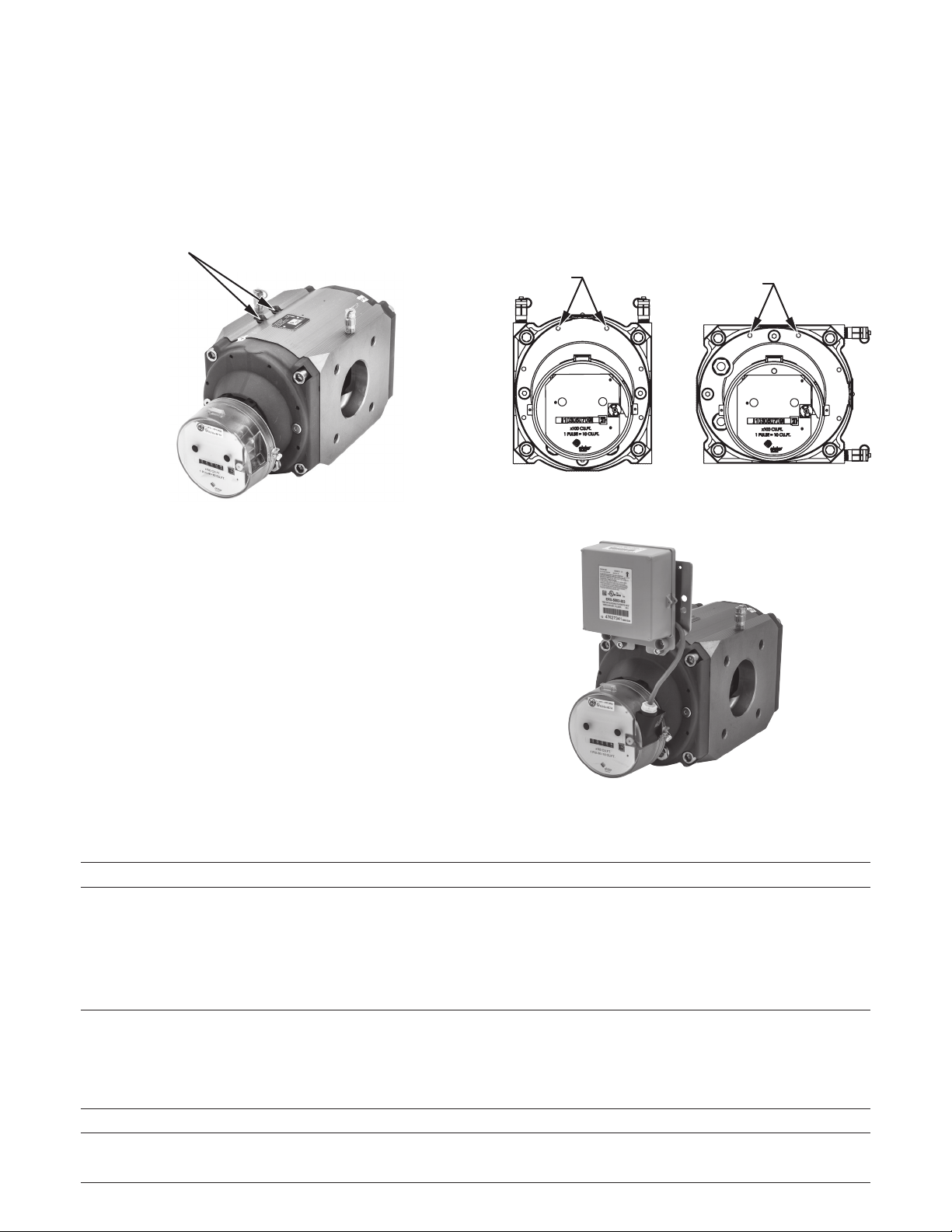
Figure 19. Horizontal installation
14. Auxiliary Equipment Mounting
All RABO meters are equipped with threaded holes for mounting
compact, lightweight auxiliary equipment [Figures 19 and 20].
All holes are M6 x 1 by 10mm deep. Heavier equipment should
be pipe or wall mounted adjacent to the meter. Elster provides
customized brackets for commonly used equipment [Figure 21].
Please contact your local Elster representative for details.
NPT AUXILIARY PORTS
Figure 18. Auxiliary ports
Figure 20. Vertical installation
13. Thermowell
All RABO meters come equipped with two (2) ¼" NPT auxiliary
ports on the meter body [Figure 18], which can be used for sensing
pressure and temperature of the flowing gas. A thermowell is
required when using a temperature sensing device. Thermowells
are available as accessories to the meter.
a) Installing a Thermowell
1. If meter is not installed in the gas piping, go to Step 5.
2. Slowly open bypass valve.
3. Slowly close the meter’s outlet valve, then the inlet valve.
4. Slowly, completely depressurize the meter piping.
5. Remove one of the plugs in the meter body by using a
¼" hex key.
6. Apply Teflon tape or pipe dope to the male threads of the
thermowell. Wipe excess pipe dope off the thermowell
probe and leading threads to ensure no pipe dope
enters the metering chamber.
7. Screw the thermowell into the meter and tighten to
18 ft-lbs.
8. Re-pressurize the meter as instructed in Start-up/
Commissioning (see section 6). Figure 21. Auxilary equipment mounted
ACCESSORY
MOUNT HOLES

Elster American Meter Company, LLC
2221 Industrial Road
Nebraska City, NE 68410
USA
T +1 402 873 8200
F +1 402 873 7616
www.elster.com/gas
© 2014 by Elster. All rights reserved. Information contained
herein is subject to change without notice. Contact your Elster
representative for the most current product information.
Elster and Elster Logo are trademarks of Elster American Meter
Company LLC.
EAM-IM5910 11/14
About Elster Gas
Elster provides best-in-class measurement and regulation products, systems and
solutions for the safe control and delivery of natural gas across the globe.
Trusted Brands
• Elster American Meter Company, LLC
• Elster Perfection Corporation
• Elster Instromet
• Elster Canadian Meter Company, LLC
• Elster Gas Depot
• Elster Meter Services
This manual suits for next models
3
Table of contents
Other Elster Instromet Measuring Instrument manuals


Popular Measuring Instrument manuals by other brands


Vitalograph
Vitalograph micro 6300 Instructions for use

NIEUWKOOP
NIEUWKOOP GT1050 user manual

Solare Datensysteme
Solare Datensysteme Solar-Log 200 installation manual

Laser Technology
Laser Technology TruPulse 200L user manual

E Instruments
E Instruments CT 100 O manual

Bushnell
Bushnell TOUR V3 instructions


