Elster Instromet RVG User manual

Instruction Manual
Rotary Gas Meters
Type RVG · RVG-ST
Betriebsanleitung
Drehkolbengaszähler
Typ RVG · RVG-ST
Mode d’emploi
Compteur de gaz à pistons rotatifs
Type RVG · RVG-ST
Manual de instrucciones
Contador de gas de pistones rotativos
Modelos RVG · RVG-ST
Istruzioni d’uso
Contatore gas a pistoni rotanti
Tipo RVG · RVG-ST
Installatie voorschrift
Rotorgasmeters
Type RVG · RVG-ST
Elster GmbH
Steinern Straße 19 · 55252 Mainz-Kastel
Tel. +49 (0)6134/605-0 · Fax +49 (0)6134/605-390
www.elster-instromet.com
73019203f/04.2009/A P&M
1© Elster GmbH · All rights reserved · Subject to technical modification
English
Elster-Instromet
Deutsch
Nederlands Italiano Español Français
Instruction Manual
Rotary Gas Meters
Type RVG · RVG-ST
Betriebsanleitung
Drehkolbengaszähler
Typ RVG · RVG-ST
Mode d’emploi
Compteur de gaz à pistons rotatifs
Type RVG · RVG-ST
Manual de instrucciones
Contador de gas de pistones rotativos
Modelos RVG · RVG-ST
Istruzioni d’uso
Contatore gas a pistoni rotanti
Tipo RVG · RVG-ST
Installatie voorschrift
Rotorgasmeters
Type RVG · RVG-ST

2© Elster GmbH · All rights reserved · Subject to technical modification
Elster-Instromet

3© Elster GmbH · All rights reserved · Subject to technical modification
English
Elster-Instromet
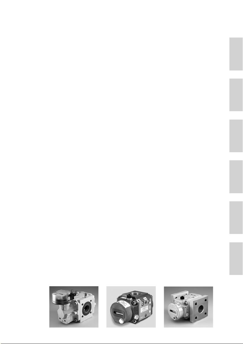
RVG G16-G400
RVG-ST G10-G25, threaded version RVG-ST G10-G25, flanged version
Instruction Manual
Rotary Gas Meters
Type RVG · RVG-ST

4© Elster GmbH · All rights reserved · Subject to technical modification
Elster-Instromet

5© Elster GmbH · All rights reserved · Subject to technical modification
English
Elster-Instromet
Contents
1. Staff .......................................................................................................................... 06
2. Legal Declarations .................................................................................................... 06
3. Intended Use and Field of Application ..................................................................... 57
4. Technical Data .......................................................................................................... 08
5. Operating Location ................................................................................................... 09
6. Installation Position, Flow Direction and Wall Clearance ......................................... 09
7. Installation / Connection......................................................................................... 111
8. Lubrication and Maintenance ................................................................................... 13
9. Commissioning ......................................................................................................... 15
10. Function Check ........................................................................................................ 16
11. Pulse Generators ...................................................................................................... 16
12. Pressure Test Point .................................................................................................. 18
13. Temperature Test Points .......................................................................................... 18
14. Index Versions .......................................................................................................... 19
15. Absolute ENCODER S1D ......................................................................................... 20
16. Care and Cleaning .................................................................................................... 21
17. Recycling and Environmental Protection ................................................................. 21
18. Annex A (ATEX Approvals) ....................................................................................... 22
19. Annex B (Plastics Used) ........................................................................................... 23
20. Annex C (Declaration of Conformity) ........................................................................ 24

6© Elster GmbH · All rights reserved · Subject to technical modification
Elster-Instromet
1. Staff
2. Legal Declarations
These Instructions are aimed at staff who have adequate specialist and technical
knowledge (in Germany, for instance, in accordance with DVGW Codes of Practice 492 and
495 or comparable technical regulations) on the basis of their training and experience in the
sector of energy and gas distribution.
–Declaration of Conformity – see Annex C.
–Period of validity of calibration – this is based on the regulations of the country concerned,
in which the rotary gas meter will be used.
–The calibration of rotary gas meters is only valid for the period of validity of calibration.
Once this has elapsed, rotary gas meters may no longer be used for purposes which are
subject to obligatory calibration.
7© Elster GmbH · All rights reserved · Subject to technical modification
English
Elster-Instromet
3. Intended Use and Field of Application
This product is intended
for calibratable volumetric metering of
–flammable gases: natural gas/town gas/butane,
–non-flammable gases: air/nitrogen/inert gases,
–and is suitable for use in potentially explosive atmospheres of Category 2 (Zone 1) of
Class EX II 2 G c IIC.
Other fields of application / media on request.
This product is not intended for
–metering of aggressive gases, e.g. biologically produced methane or sewage gases,
oxygen, acetylene.
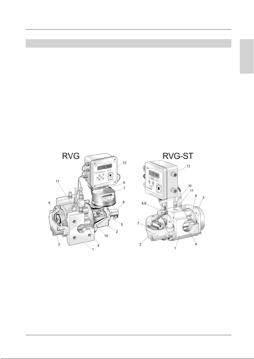
1Meter housing 17Index head
2Housing cover (front) 18HF pulse generator
3Housing cover (rear) 19LF pulse generator
4Pistons 10 Pressure test point
5Gear assembly 11 Temperature test point
6Synchronising gears 12 Volume corrector (optional)
Please contact your Elster-Instromet Customer Service (Tel. +49 (0)6134-605-0 / -346)
for assistance in commissioning, maintenance and installation of encoders, pulse generators
and volume correctors for instance.
8© Elster GmbH · All rights reserved · Subject to technical modification
Elster-Instromet
4. Technical Data
Rotary gas meters in accordance with DIN EN 12480
Type RVG-ST RVG
Size: G10 to G25 G16 to G400
Nominal diameter: DN 25 to DN 50 DN 40 to DN 150
Pressure ratings: PN 10/16 or CLASS 150
Temperature ranges:
– gas / ambient / storage -20 ˚C to +60 ˚C*
– gas / ambient / storage (MID) -10 °C to +55 °C-25 ˚C to +55 ˚C*
Housing material: Aluminium Spheroidal graphite
cast iron or aluminium
Mechanical ambient conditions: M1
*Measuring ranges ≥1:130, -10˚C
Pulse generators
LF pulse generator E1 Wiegand pulse generator HF pulse generator
(reed contact) (in accordance with
DIN EN 50227)
Umax = 24 V Umax = 30 V Urated = 8 V DC
Imax = 50 mA Imax = 100 mA I 욷2.1 mA (exposed)
I 울1.2 mA (covered)
Pmax = 0.25 VA Pmax = 600 mW U 쏝5.9 V (exposed)
U 쏜6.8 V (covered)
Ri= 100 Ω(series resistor) Ri= 1 kΩ
Absolute ENCODER S1D
Absolute ENCODER S1D
Index
Number of indexes 2
Number of digit rollers per index 8
Safety class IP 67
Interfaces NAMUR (II 2 G EEx ia IIC T4) or
ATEX approval SCR / SCR Plus (II 2 G EEx ib IIB T4) or
M-BUS
LF pulse generator Optional or retrofittable INS-10, -11, -12
Umax = 24 V, Imax = 50 mA, Pmax = 0.25 VA,
Ri= 100 Ω(series resistor)

9© Elster GmbH · All rights reserved · Subject to technical modification
English
Elster-Instromet
5. Operating Location
6. Installation Position, Flow Direction and Wall Clearance
If you …
–wish to mix in odorisation agents or
– use solenoid valves,
please always fit them only downstream of the meter. Otherwise, the device may be
damaged.
The flow through the meter must be free of vibrations / pulsations in order to avoid
measuring errors.
Compliance with the specified operating and ambient conditions as indicated on the type
label is absolutely essential for safe operation of the meter and additional equipment.
The gas may not contain suspended particles > 50 m. In addition, the gas must be dry.
Otherwise, the meter may be damaged.
To protect the meter, a coarse filter (cone strainer with mesh size 250 m) must be installed
on all new installations, and is also recommended for existing installations. The strainer
should be removed after approximately 4 to 6 weeks.
Type RVG:
Gas can be passed through the Type RVG rotary gas meter both horizontally and vertically.
The index head can be turned through up to 355°for optimum ease of reading in different
installation/operating positions. If the meter is equipped with oil-level gauge glasses on just
one side, then the meter must be mounted with a gap (욷B + 30 mm) from the centre of the
pipe to the wall, in order to facilitate access for maintenance (Figure 1 and Table 1):
Figure 1: Horizontal flow from left to right and from right to left
Wall Wall

10 © Elster GmbH · All rights reserved · Subject to technical modification
Elster-Instromet
ABB
with HF transmitter
G16 – G65 120 190 250
G100 170 240 300
G160 200 245 305
G250 230 275 335
G400 290 335 395
Table 1: Minimum wall clearance A or B in mm
Type RVG-ST:
The Type RVG-ST rotary gas meter can be installed both horizontally and vertically, but the
direction of flow must be set at the factory. The meter only has an oil-level gauge glass on
the front and must be mounted with a gap of at least 85 mm between the pipe centre and the
wall (Figure 2).
Figure 2: Horizontal flow from left to right
Wall
11© Elster GmbH · All rights reserved · Subject to technical modification
English
Elster-Instromet
7. Installation / Connection
Warning! Never clean the plastic hood of the index with a
dry cloth owing to the risk of explosion resulting from
electrostaticdischarge!Please only ever use an adequately
moistened cloth!
Before installation please ensure:
– that the protective caps and/or plastic sheeting is or are removed,
–that the meter and accessories have been inspected for transport damage,
– that the pistons rotate easily in the measuring chamber (e.g. by blowing on them),
–that the accessories have been checked for completeness (e.g. plug connectors, oil for
initial filling).
You will require the following items for installation:
Type RVG and Type RVG-ST with flange:
–Suitable seals/gaskets for the relevant gases.
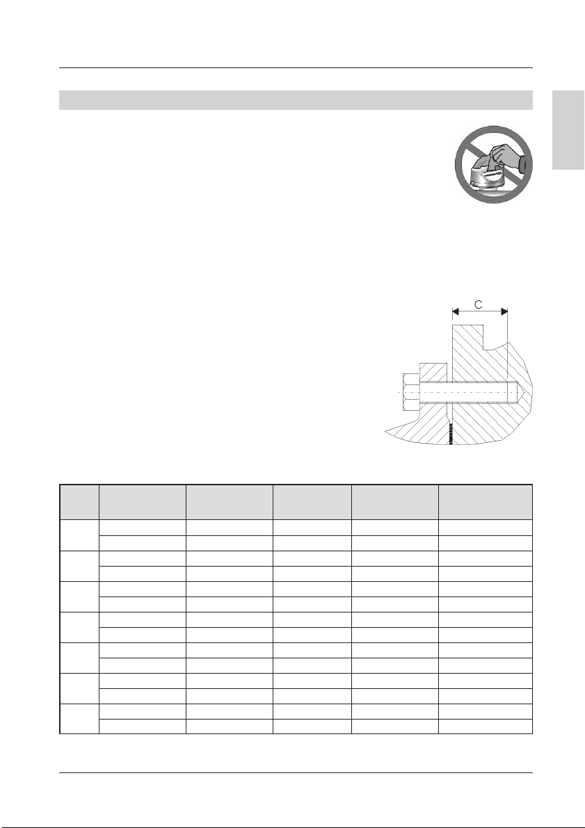
–For installing the meter in the pipe, use screws in accord-
ance with DIN 931. The screw length must be selected so
that a thread reach of C mm (Table 2) into the meter is
guaranteed (Figure 3). The recommended maximum
tightening torque is defined in the table 2.
Figure 3
DN Screw size Screws Thread reach Max. tight-
per meter C mm ening torque Nm
25 PN 10/16 M12 8 14 – 20 23
CLASS 150 M12 8 14 – 20 25
32 PN 10/16 M16 8 16 – 22 46
CLASS 150 M12 8 14 – 20 31
40 PN 10/16 M16 8 16 – 22 58
CLASS 150 M12 8 14 – 20 36
50 PN 10/16 M16 8 16 – 22 60
CLASS 150 M16 8 16 – 22 47
80 PN 10/16 M16 16 16 – 22 52
CLASS 150 M16 8 16 – 22 83
100 PN 10/16 M16 16 16 – 22 58
CLASS 150 M16 16 16 – 22 59
150 PN 10/16 M20 16 20 – 28 83
CLASS 150 M20 16 20 – 28 96
Table 2: Flange screws

12 © Elster GmbH · All rights reserved · Subject to technical modification
Elster-Instromet
Type RVG-ST threaded version:
–Suitable seals/gaskets for the relevant gases.
–You will require the following connection elements (which can be ordered from Elster-
Instromet) for installing the meter into the pipe:
Figure 4: Connection elements for Type RVG-ST
Then install the meter (Type RVG and Type RVG-ST):
– gas-tight,
–with the supplied accessories,
–only in flow direction (as marked by an arrow on the meter housing or index head S1D),
– only unstressed,
–he piston axes must be horizontal, check using a spirit level (Figure 5),
–when fitting the seals and gaskets, ensure that they are aligned concentrically and do
not project into the flow channel,
–weatherproof.
If you have specified the installation or operating position when ordering, all attachments will
have been fitted in accordance with the installation position ex-works.
1Pipe
2Insert
3Union nut
4O-ring
5Threaded part
6O-ring
7Strainer
8Retaining ring
Figure 5: Checking the meter using a spirit level
Horizontal installation Vertical installation Incorrect installation

13© Elster GmbH · All rights reserved · Subject to technical modification
English
Elster-Instromet
–Only use original spare parts supplied by Elster-Instromet.
–Fill with oil before commissioning.
–To fill with oil, depressurise the meter.
–The quantity of oil required for operation, as well as a syringe for filling, are included in
the delivery.
–Use Shell Morlina S2 BL 10 oil or equivalent (e.g. Shell Risella 917) (Inspection kit Ident.
No. 73016605 or 73014893).
–The front and rear oil chambers are linked with one another, so that the meter can be
serviced with oil from just one side.
Type RVG:
–There are three openings available for filling or draining oil, and two oil-level gauge
glasses on the front and (optionally) on the rear of the meter (Figure 7).
–Unscrew and remove the oil filler plug (E, Figure 7) from the front housing cover.
–Remove one oil filler plug (E) from the rear housing cover, so that the oil can flow more
easily into the rear oil chamber.
Type RVG-ST:
–In the case of horizontal flow, there are two openings available for filling with oil (E or V).
The drain opening A is located at the lowest point. The oil-level gauge glass O is located
on the front side of the meter, below the index (Figure 8, left).
–In the case of vertical flow, there is only one opening available (E) for filling with oil. The
drain opening A is located at the lowest point. The oil-level gauge glass is now located
on the right on the front housing cover (Figure 8, right).
–Remove the oil filler plug (E, and if applicable V) from the front housing cover.
Type RVG and Type RVG-ST:
–Fill with oil slowly, using the syringe. It will take 5 to 10
minutes until the oil reaches the same level in both oil
chambers. The oil volume is correct when the oil level is
located in the lower third of the gauge glass (Figure 6). The
required quantity of oil depends on the installation position;
for guidance, see Tables 3 and 4.
8. Lubrication and Maintenance
Figure 6:
Oil level in gauge glass
If you wish to install the unit vertically at a later point, you must turn any other attachments,
e.g. volume corrector, through 90°.
We recommend that you contact our Elster-Instromet Customer Service (Tel. +49
(0)6134-605-0 / -346) for such conversion work.

14 © Elster GmbH · All rights reserved · Subject to technical modification
Elster-Instromet
–Excess lubricant can contaminate the measuring chamber.
– Re-close all oil filler necks (seal using O-rings).
–The time interval for checking the oil level depends on the individual operating conditions
and gas qualities. Once it has been commissioned, the measuring instrument does not
require any special servicing. In the case of operation with natural gas, the oil should
generally be changed every 5 years, or earlier in the case of contamination.
Instructions for checking oil:
–During operation the oil is distributed in the meter, which means that under certain
circumstances no oil is visible in the gauge glass. The oil level must therefore be checked
once the meter has been idle for approx. 5 minutes. To refill it, the meter must be
depressurised.
–Never transport a rotary gas meter containing oil. Make sure that the oil is drained out
before transporting the meter (e.g. when sending the meter for repairs), otherwise the oil
will penetrate the measuring chamber and damage the meter.
Flow Flow Flow Flow
(vertical) (horizontal) (vertical) (horizontal)
from bottom to top from left to right from top to bottom from right to left
E= Oil filler neck O= Oil-level gauge glass A= Oil drain sleeve
Figure 7: Permitted operating positions, oil filling and oil-level display for Type RVG
Oil quantity
Flow direction RVG with GGG 40 housing RVG with aluminium housing
G16 – G100 G160 – G250 G16 – G100 G160 – G400
Horizontal Approx. 100 ml Approx. 240 ml Approx. 65 ml Approx. 190 ml
Vertical Approx. 225 ml Approx. 525 ml Approx. 170 ml Approx. 535 ml
Table 3: Guide values for oil quantity on commissioning and for oil changes for Type RVG

15© Elster GmbH · All rights reserved · Subject to technical modification
English
Elster-Instromet
9. Commissioning
Flow (horizontal) Flow (vertical)
from left to right from top to bottom
E = Oil filler neck O = Oil-level gauge glass
A = Oil drain sleeve V = Screw plug
Figure 8: Horizontal and vertical installation positions, oil filling and oil-level display for Type
RVG-ST
Flow direction Oil-level gauge glass Oil quantity
Horizontal On the front side Approx. 25 ml
of the meter
Vertical On the side Approx. 80 ml
of the housing cover
Table 4: Guide values for oil quantity on commissioning and for oil changes for Type
RVG-ST
In order not to damage the meter,
–slowly fill the system until operating pressure is reached.
– The pressure rise may not exceed 350 mbar/s. You should use a bypass line for filling
(recommendation: 12 mm pipe diameter).
–Do no exceed the measuring range even briefly!
–Conduct a tightness test!
Attention: you must please note the instructions in Section 5, „Operating Location“.
Oil level
Oil level
16 © Elster GmbH · All rights reserved · Subject to technical modification
Elster-Instromet
10. Function Check by Means of Pressure Loss Measurement
11. Pulse Generators
IN-S11
IN-W11
The correct function of the rotary gas meter can be inferred by measuring the pressure loss.
If the pressure loss has increased by more than 50% compared to the value at the initial start-
up, then there may be dirt, for example, in the measuring chamber that can lead to an
incorrect result being obtained. In comparing the pressure loss, the load and the operating
pressure must be considered.
We recommend recording the pressure loss at several points in the flow when commissioning
and logging these with the current operating pressure. If the current flow rate and operating
pressure in later checks deviate from the original values, then the nominal pressure loss can
be calculated from the original values. The pressure loss is proportional to the absolute
pressure (pabs) and the square of the flow rate (Q).
욼p ~ pabs · Q2
Type RVG:
LF pulse generators (Type IN-S) or Wiegand pulse
generators (Type IN-W) may be plugged onto the side
of the index cover for volume pulse output to external
devices (e.g. a volume corrector).
Fit the pulse generator (if required) as follows:
–Slide both guides of the pulse generator into the
guide slot on the index cover until the guides can be
heard to engage (clicking sound).
–Assign the terminals on the plug in accordance with
the pin assignment on the meter/pulse generator.
– Use screened cables to the external device (in
accordance with DIN 60079-14).

17© Elster GmbH · All rights reserved · Subject to technical modification
English
Elster-Instromet
A1K
Coupler socket
Flange connector
YoucanuseHFpulsegeneratorsforhigherfrequencies
(Type A1K) (optional). HF pulse generators are screwed
pressure-tight into the housing cover. However, the
connection plug can be turned.
–Assign the terminals on the plug in accordance with
the pin assignment on the unit.
–Use a screened cable to the external device (in
accordance with DIN 60079-14).
Pulse generators for subsequent installation are also available.
HF pulse generators (Type A1K) can, however, be fitted only by the Elster-Instromet
Customer Service (Tel. +49 (0)6134-605-0 / -346). By contrast, you can connect the plug
yourself, as described above.
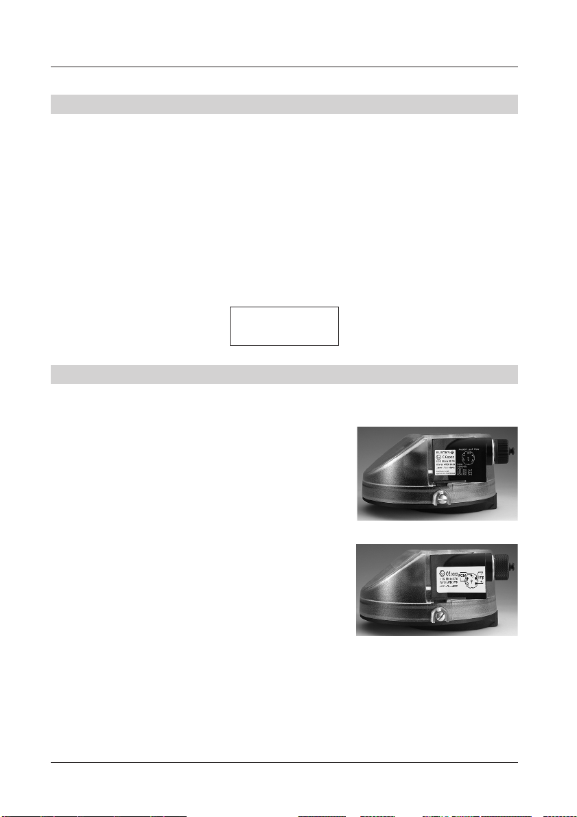
Type RVG-ST:
Elster-Instromet rotary gas meters of Type RVG-ST can be equipped with one or two low
frequency (LF) pulse generators. In addition, the unit can also be equipped with a monitoring
contact (PCM) for checking open circuits or manipulation.
In addition, a high frequency (HF) pulse generator (optional) is also available. The pulse values
of the fitted pulse generators are stated on the meter.
The pin assignments of the pulse generators are stated on an adhesive label on the unit.
These assignments show the plan view of the pin contacts of the fitted flange connector or
the view of the soldered connection terminals of the coupler socket.
Figure 9: Coupler socket and flange connector for Type RVG-ST
Warning!All pulse generators are intrinsically safe and may be connected onlyto intrinsically
safe circuits if used in potentially explosive atmospheres. The safety barriers must comply
with the requirements of ignition protection EEx ib IIC (see also Marking in Annex A).

18 © Elster GmbH · All rights reserved · Subject to technical modification
Elster-Instromet
12. Pressure Test Point
13. Temperature Test Points
A straight male coupling in accordance with DIN 2353 is pre-fitted on the meter housing for
connection of a pressure sensor for instance.
The pressure test point is marked pmand is designed for connection of d = 6 mm steel tube
in accordance with DIN EN 10305-1 (e.g. steel grade E 235).
Important: Do not connect the straight male coupling to pipes made of stainless steel or
pipes made of nonferrous materials.
Note: We recommend that you use original Parker-Ermeto pipe unions only. Functional
safety and reliability are ensured only if the material combination of the union component and
the pipe are intermatched. We recommend that you contact our Elster-Instromet Customer
Service (Tel. +49 (0)6134-605-0 / -346) for conversion work and when installing additional
devices.
Youcanuseamaximum of twotemperaturesensors
for measuring the gas temperature in the meter
housing
(Series RVG EBL67, Ident. No. 73013525),
(Series RVG-ST EBL45, Ident. No. 73013410).
Note that temperature measurement on measuring
systems in the open air may be influenced by the
ambient temperature. For this reason, the metering
elements outside the pipe should be adequately
insulatedagainst ambient temperature influences. In
order to achieve optimum thermal conduction, also
fill the thermowell(s) with a heat-conductive fluid or
paste.
If no temperature test points in the meter housing are planned, measure the temperature
in the pipe upstream of the rotary gas meter at a distance of up to 3 x DN.
19© Elster GmbH · All rights reserved · Subject to technical modification
English
Elster-Instromet
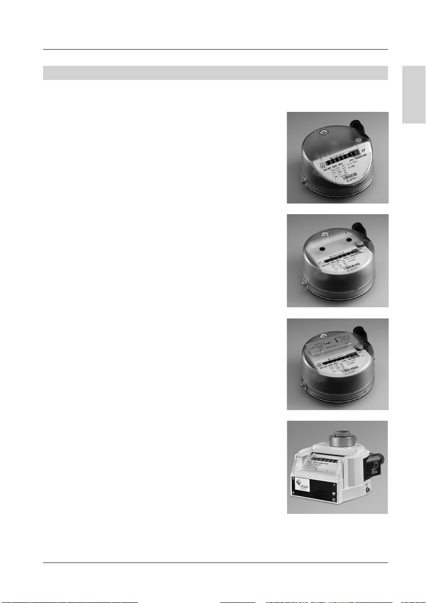
14. Index Versions (Type RVG)
S1V
Version II
S1
S1D
The meter can be equipped with various index versions:
Index head S1
–This is the standard version with an 8-digit mechanical
roller index.
–Provides universal read-off.
– Can be rotated up to 355°about its axis.
–Suitable for outdoor installation.
–Designed for LF pulse generators which can be plugged
on from the outside and which can be exchanged on
site.
Index head S1V
–This has the same features as index head S1.
–Themechanical roller index canbe read off fromthe top.
Index head S1D
–This has the same features as index head S1V.
–It has two 8-digit mechanical roller indexes (depending
on the flow direction, one index will be covered).
–MeterswithS1Dscanbeusedinallinstallationpositions.
Index head MI-2
–provides universal read-off,
–can be rotated up to 355˚ about its axis,
–Aluminium cover,
–can be optionally fitted with a mechanical index drive
pointing upwards or backwards in accordance with EN
12480,
–designed for LF pulse generators which can be plugged
on from the outside and which can be exchanged on
site,
–equipped with dry cartridge,
lifetime of cartridge depends on installation conditions
(minimum life 12 months),
replace dry cartridge when colour has changed from blue to pink.
MI-2
This manual suits for next models
1
Table of contents
Languages:
Other Elster Instromet Measuring Instrument manuals


