BCU 480 · Edition 06.07
2
t= To be continued
Contents
Burner control units BCU 480 ....................... 1
Contents........................................2
1 Application.....................................4
2 Examples of application ..........................6
2.1 Stage-controlled main burner with alternating
pilot burner ......................................6
2.2 Stage-controlled main burner with permanent
pilot burner ......................................7
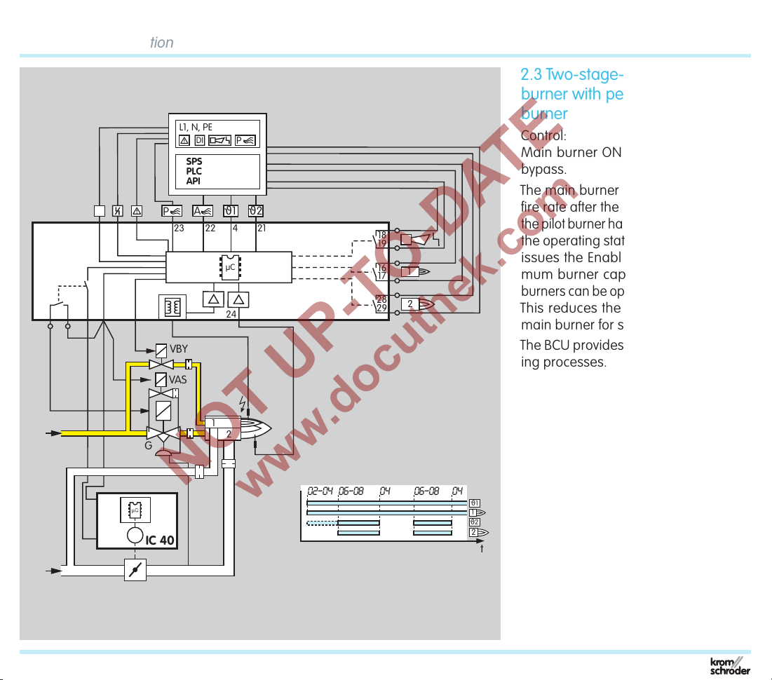
2.3 Two-stage-controlled main burner with permanent
pilot burner ......................................8
2.4 Modulating-controlled burner ....................9
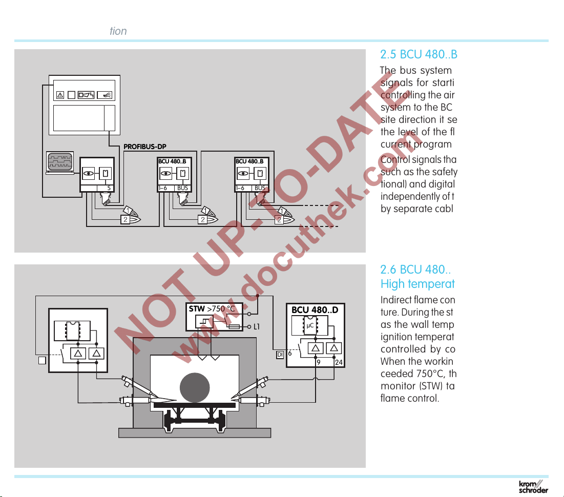
2.5 BCU 480..B1 for PROFIBUS-DP ...................10
2.6 BCU 480..D:High temperature equipment .........10
3 Certification ....................................11
3.1 EC type-tested and certified ......................11
3.2 AGA .........................................11
3.3 FM ..........................................11
3.4 Profibus User Organisation ......................11
4 Function...................................... 12
4.1 Connection diagrams ..........................12
4.1.1 BCU 480.........................................12
4.1.2 BCU 480..B1 with Profibus ..........................13
4.1.3 BCU 480..P with 16-pin industrial plug connector .......14
4.2 BCU 480 program sequence ....................16
4.3 Program status and fault messages ..............19
5 Parameters ...................................20
5.1 Scanning the parameters . . . . . . . . . . . . . . . . . . . . . . . 21
5.2 Flame control.................................22
5.2.1 Flame signal, pilot burner ......................... 22
5.2.2 Flame signal, main burner ........................ 22
5.2.3 Program status when the most recent fault occurred .. 22
5.2.4 Switch-off threshold of the flame amplifier ........... 22
5.2.5 High temperature operation in the case of BCU..D2 or
BCU..D3 . . . . . . . . . . . . . . . . . . . . . . . . . . . . . . . . . . . . . . . . . . . . 23
5.2.6 UVS check...................................... 26
5.3 Pilot and main burner monitoring ................27
5.3.1 Permanent pilot burner ........................... 28
5.3.2 Interrupted pilot burner ........................... 28
5.4 Behaviour in start-up position/standby............29
5.4.1 Flame simulation check in start-up position/standby ... 29
5.4.2 Minimum burner pause time tBP ................... 30
5.5 Behaviour during start-up ......................31
5.5.1 Safety time on start-up tSA ..........................31
5.5.2 Flame proving period tFS ......................... 32
5.5.3 Minimum combustion time tB..................... 32
5.5.4 Burner start-up attempts.......................... 33
5.6 Behaviour during operation .....................35
5.6.1 Safety time during operation tSB for pilot and
main burners........................................ 35
5.6.2 Fault lock-out or restart, pilot burner ................ 35
5.6.3 Immediate fault lock-out following flame failure....... 35
5.6.4 Fault lock-out or restart, main burner.................37
5.7 Air valve control on BCU..L ......................39
5.7.1 Purge .......................................... 39
5.7.2 Cooling in start-up position/standby ................ 39
5.7.3 Burner start..................................... 39
5.7.4 Air valve opens in the case of external activation
(not during start-up) .................................. 40
5.7.5 Air valve opens in the case of external activation
(even during start-up) ..................................41
5.7.6 Air valve opens with valve V2 ...................... 42
5.7.7 Air valve opens with operating signal ............... 43
5.7.8 Low fire over run time tKN after a normal shut-down ... 44
5.7.9 Behaviour of the air valve in the event of a
fault lock-out ........................................ 45
5.8 Manual mode ................................46
5.8.1 Manual mode limited to 5 minutes.................. 46