manuals.online logo
Brands
  1. Home
  2. •
  3. Brands
  4. •
  5. BENDIX
  6. •
  7. Control Unit
  8. •
  9. BENDIX TW-2 User manual

BENDIX TW-2 User manual

1
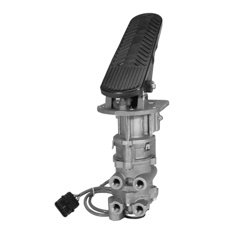
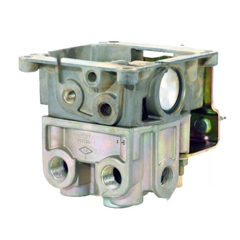
Figure 1 – Bendix®TW-2™, TH-3™and PE-4™Control Valves Maintenance Kit
BENDIX®TW-2™, TH-3™AND PE-4™CONTROL VALVES MAINTENANCE KIT
Position
1
Position
2
Position
3
Screw
Lever/Cam
Pin
Plunger
(x2)
6
54
3
2
Inlet Plate
Lock Washer
Cap Screws
Body
Spring
Lever Positioner
Figure 1
Figure 2
Figure 3
*NOTE: Some valves (TW-2, TH-3
and PE-4) use a single large inlet
plate o-ring and some models use
two smaller o-rings.
Kit Contents
Item No. Description Qty.
2* Inlet Plate O-Ring 1
2* Inlet Plate O-Ring 2
3 Valve Spring 2
4 Valve 2
5 Plunger Spring 2
6 Plunger O-Ring 2
7 Tube of Lubricant 1
7
GENERAL SAFETY GUIDELINES
WARNING! PLEASE READ AND FOLLOW THESE INSTRUCTIONS
TO AVOID PERSONAL INJURY OR DEATH:
When working on or around a vehicle, the following guidelines should be observed AT ALL TIMES:
▲Park the vehicle on a level surface, apply the
parking brakes and always block the wheels.
Always wear personal protection equipment.
▲Stop the engine and remove the ignition key
when working under or around the vehicle.
When working in the engine compartment,
the engine should be shut off and the ignition
key should be removed. Where circumstances
require that the engine be in operation, EXTREME
CAUTION should be used to prevent personal
injury resulting from contact with moving,
rotating, leaking, heated or electrically-charged
components.
▲Do not attempt to install, remove, disassemble
or assemble a component until you have read,
and thoroughly understand, the recommended
procedures. Use only the proper tools and
observe all precautions pertaining to use of those
tools.
▲If the work is being performed on the vehicle’s
air brake system, or any auxiliary pressurized air
systems, make certain to drain the air pressure
from all reservoirs before beginning ANY work
on the vehicle. If the vehicle is equipped with a
Bendix®AD-IS®air dryer system, a Bendix®DRM™
dryer reservoir module, or a Bendix® AD-9si®air
dryer, be sure to drain the purge reservoir.
▲Following the vehicle manufacturer’s
recommended procedures, deactivate the
electrical system in a manner that safely removes
all electrical power from the vehicle.
▲Never exceed manufacturer’s recommended
pressures.
▲Never connect or disconnect a hose or line
containing pressure; it may whip and/or cause
hazardous airborne dust and dirt particles. Wear
eye protection. Slowly open connections with
care, and verify that no pressure is present. Never
remove a component or plug unless you are
certain all system pressure has been depleted.
▲Use only genuine Bendix®brand replacement
parts, components and kits. Replacement
hardware, tubing, hose, fi ttings, wiring, etc. must
be of equivalent size, type and strength as original
equipment and be designed specifi cally for such
applications and systems.
▲Components with stripped threads or damaged
parts should be replaced rather than repaired.
Do not attempt repairs requiring machining or
welding unless specifi cally stated and approved
by the vehicle and component manufacturer.
▲Prior to returning the vehicle to service, make
certain all components and systems are restored
to their proper operating condition.
▲For vehicles with Automatic Traction Control
(ATC), the ATC function must be disabled (ATC
indicator lamp should be ON) prior to performing
any vehicle maintenance where one or more
wheels on a drive axle are lifted off the ground
and moving.
▲The power MUST be temporarily disconnected
from the radar sensor whenever any tests USING
A DYNAMOMETER are conducted on a vehicle
equipped with a Bendix® Wingman®system.
▲You should consult the vehicle manufacturer's operating and service manuals, and any related literature,
in conjunction with the Guidelines above.
2
3
REMOVAL
1. With the vehicle on a level surface, park the vehicle
by means other than the air brakes and drain all air
pressure from all reservoirs.
2. Identify all air lines and their connections to the valve
and disconnect.
3. Remove the two Phillips®head screws securing the dial
plate to the valve and dash panel and remove the valve.
DISASSEMBLY
NOTE: Before beginning disassembly of the valve, mark
the relationship of the lever and cam to the body. The lever
must be placed back in the valve body in the same position
in order to ensure proper operation. DO NOT change the
lever position end for end. Most lever/cams have a locating
slot cut in them.
1. Remove the cap screws and lock washer and remove
the inlet plate. Note whether one or two inlet plate
o-rings (2) are used. *See note on page 1.
2. Remove and discard the o-ring (2), both springs (3) and
both inlet valves (4).
3. Remove the pin and lift the lever out of the body.
4. Remove both plungers and their return springs (5).
5. Remove the lever positioner and its spring, if the valve
is so equipped.
6. Remove the o-ring (6) from both plungers and discard
the o-rings.
ASSEMBLY
Prior to assembly, clean the lever and valve body in
mineral spirits and dry thoroughly. Lubricate o-rings and
o-ring bores with the lubricant (7) supplied with this kit.
1. Install both inlet valves (4) and inlet valve springs (3) in
the valve body.
2. Install the o-ring or o-rings (see NOTE* on page 1) in
the valve body.
3. Install the inlet plate and secure with cap screws and
washer. Torque to 50-180 in-lbs.
4. Install the o-ring (6) on the plungers.
5. Install the plunger return springs (5) and install the
plungers in the valve body.
6. Install the lever positioner spring and lever positioner if
valve is so equipped.
7. Note the markings made on the lever/cam and valve
body during disassembly and position the lever in the
valve body.
8. Install the pin to secure the lever/cam.
OPERATING AND LEAKAGE CHECKS
Connect a 100 psi air source to the supply port(s) and
connect an air gauge to each delivery port. With the lever
in the number 1 position, as noted in Figure 3, apply a soap
solution to the exhaust openings in the valve body. No
leakage is permitted. Note which delivery gauge registers
pressure (if either do). Move the lever to position 2, if the
valve has this position, and wait 20 seconds before applying
a soap solution and checking the delivery port gauges.
Repeat this procedure for position 3.
INSTALLATION
1. Remount the valve in the dash panel using the two
Phillips head screws to secure the dial plate and valve.
2. Notingtheairlineidenticationmadeduringremoval,
reconnect the air lines to the proper ports.
3. Before moving the vehicle, build the air system pressure
and operate the valve to determine if it functions
properly in the system. If operation is incorrect, check
the lever/cam installation and the air line connections.
S-0308 Rev. 002 © 2019 Bendix Commercial Vehicle Systems LLC, a member of the Knorr-Bremse Group • 12/19 • All Rights Reserved
4
Log-on and Learn from the Best
On-line training that's available when you are 24/7/365.
Visit brake-school.com.

This manual suits for next models

2

Other BENDIX Control Unit manuals

BENDIX DV-2 AUTO RESERVOIR DRAIN VALVE User manual

BENDIX

BENDIX DV-2 AUTO RESERVOIR DRAIN VALVE User manual

BENDIX E-10 Mounting instructions

BENDIX

BENDIX E-10 Mounting instructions

BENDIX R-12DC DBL CHECK RELAY VALVE User manual

BENDIX

BENDIX R-12DC DBL CHECK RELAY VALVE User manual

BENDIX RV-3 PRESSURE REDUCING VALVE Operating and maintenance instructions

BENDIX

BENDIX RV-3 PRESSURE REDUCING VALVE Operating and maintenance instructions

BENDIX INLET REG VALVE COMP User manual

BENDIX

BENDIX INLET REG VALVE COMP User manual

BENDIX TIM G2 User manual

BENDIX

BENDIX TIM G2 User manual

BENDIX TABS-6 TRAILER ABS MODULE Mounting instructions

BENDIX

BENDIX TABS-6 TRAILER ABS MODULE Mounting instructions

BENDIX AR-2 ANTILOCK RELAY VALVE User manual

BENDIX

BENDIX AR-2 ANTILOCK RELAY VALVE User manual

BENDIX EVERFLOW User manual

BENDIX

BENDIX EVERFLOW User manual

BENDIX ATR1DC ANTILOCK TRACTION RELAY User manual

BENDIX

BENDIX ATR1DC ANTILOCK TRACTION RELAY User manual

BENDIX ST-1 User manual

BENDIX

BENDIX ST-1 User manual

BENDIX TP-2 TRACTOR PROTECTION VALVE User manual

BENDIX

BENDIX TP-2 TRACTOR PROTECTION VALVE User manual

BENDIX PR-3 User manual

BENDIX

BENDIX PR-3 User manual

BENDIX QRN-2 QUICK RELEASE VALVE User manual

BENDIX

BENDIX QRN-2 QUICK RELEASE VALVE User manual

BENDIX E-12-E-15 BRAKE VALVE User manual

BENDIX

BENDIX E-12-E-15 BRAKE VALVE User manual

BENDIX RE-4 RELAY EMERGENCY VALVE User manual

BENDIX

BENDIX RE-4 RELAY EMERGENCY VALVE User manual

BENDIX ATR-1 ANTILOCK TRACTION RELAY Service manual

BENDIX

BENDIX ATR-1 ANTILOCK TRACTION RELAY Service manual

BENDIX DOUBLE CHECK VALVES User manual

BENDIX

BENDIX DOUBLE CHECK VALVES User manual

BENDIX E-14 DUAL BRAKE VALVE User manual

BENDIX

BENDIX E-14 DUAL BRAKE VALVE User manual

BENDIX TC-7 TRAILER CONTROL BRAKE VALVE User manual

BENDIX

BENDIX TC-7 TRAILER CONTROL BRAKE VALVE User manual

BENDIX R-8R ELAY VALVE User manual

BENDIX

BENDIX R-8R ELAY VALVE User manual

BENDIX SC-3 INLINE SINGLE CHECK VALVES User manual

BENDIX

BENDIX SC-3 INLINE SINGLE CHECK VALVES User manual

BENDIX BP-1 BRAKE PROPORTIONING VALVES User manual

BENDIX

BENDIX BP-1 BRAKE PROPORTIONING VALVES User manual

BENDIX QRV QR-1 QUICK RELEASE VALVES Service manual

BENDIX

BENDIX QRV QR-1 QUICK RELEASE VALVES Service manual

Popular Control Unit manuals by other brands

TUYA WBR1D-IPEX manual

TUYA

TUYA WBR1D-IPEX manual

Lucent 5ESS DRM user guide

Lucent

Lucent 5ESS DRM user guide

CHINT Astronergy CHSM6610M installation manual

CHINT

CHINT Astronergy CHSM6610M installation manual

Stahl 8624-1 operating instructions

Stahl

Stahl 8624-1 operating instructions

Timotion TC15P Series user manual

Timotion

Timotion TC15P Series user manual

Eaton Crouse-hinds series instruction manual

Eaton

Eaton Crouse-hinds series instruction manual

Emerson Bettis 2000 Series user manual

Emerson

Emerson Bettis 2000 Series user manual

Siemens SIRIUS 3RA2130-4 A3 Series Original operating instructions

Siemens

Siemens SIRIUS 3RA2130-4 A3 Series Original operating instructions

SCHUNK ELB Series Assembly and operating manual

SCHUNK

SCHUNK ELB Series Assembly and operating manual

Wisi TANGRAM GT01W0230 quick guide

Wisi

Wisi TANGRAM GT01W0230 quick guide

ARM ARM1136JF-S Application note

ARM

ARM ARM1136JF-S Application note

evaton technologies Link user manual

evaton technologies

evaton technologies Link user manual

hyfire TAURUS TAU-MO-SB-01 quick start guide

hyfire

hyfire TAURUS TAU-MO-SB-01 quick start guide

GMI D5095S Safety manual

GMI

GMI D5095S Safety manual

ICP DAS USA I-8123W Quick start user guide

ICP DAS USA

ICP DAS USA I-8123W Quick start user guide

DF ROBOT DS1307 manual

DF ROBOT

DF ROBOT DS1307 manual

Ublox ODIN-W260 System integration manual

Ublox

Ublox ODIN-W260 System integration manual

KLINGER SCHÖNEBERG INTEC Series operating instructions

KLINGER SCHÖNEBERG

KLINGER SCHÖNEBERG INTEC Series operating instructions

manuals.online logo
manuals.online logoBrands
  • About & Mission
  • Contact us
  • Privacy Policy
  • Terms and Conditions

Copyright 2025 Manuals.Online. All Rights Reserved.