Elster EM260 User manual

Manual EM260
with Volume Corrector EK260/280
Betriebsanleitung-EM260-EK2x0_en_g.doc 1 of 6
Manual EM260
with Volume Corrector
EK220/260/280
Manual: 73021398 Version: g
Release: 03.01.2014 Edition: -
Contents
1
SAFETY INSTRUCTIONS 2
2
FEATURES 2
3
WIRING EM260
EK220/260/280 3
4
WIRING OF EM260´S COMMUNICATION INTERFACE 3
5
SETTINGS OF THE SERIAL INTERFACE IN THE EK220/260/280 3
6
SETTING THE PARAMETERS FOR THE COMMUNICATION MODULE 4
7
REPLACEMENT OF COMMUNICATION MODULES 5
8
POWER SUPPLY 5
9
OPERATING STATUS DISPLAY 5
10
JUMPER 5
11
TECHNICAL DATA 6

Manual EM260
with Volume Corretor EK260/280
2 / 6 Betriebsanleitung-EM260-EK2x0_en_g.doc
1 Safety Instructions
!
!!
!
Please read these instructions carefully before assembling, installing or commissioning
the EM260 to avoid any damage, dangers or problems.
Assembly and installation should be carried out by qualified personnel !
!
!!
!
The ‘AC’ version of the EM260 has a power supply of 90...260 V. Do not touch any live
parts as this is extremely dangerous !
Shut off the power supply before carrying out any installation work and before opening the
housing !
Switch the power back on only after all of the work has been completed and the housing
has been firmly closed!
Other notes:
The PE connections in both the EM260 and the EK2x0 should be as short as possible
and have as wide a cross-section as possible.
When assembling the front cover, ensure that the flat-strip cable for connecting the LEDs
integrated into the front transparent film is plugged into the 4x1 pin strip ST8!
2 Features
•Modem for use with ELSTER LIS-100 and LIS-200 end devices
•Internal TTL interface for one of the following communication modules:
– Standard analogue modem
– ISDN adapter
– Ethernet LAN adapter.
– ELSTER-CL0 interface card
•RS232 / V.24 interface to end device (RxD, TxD, Gnd, DCD, DTR, RI), galvanically separated
•Power supply for EK2x0 and EK-88
•5 VDC outputs for interface component of LIS100 devices, only switched on during modem
connection (online status)
•EMC in accordance with standards EN55011 Class B, EN55024, EN61326 and EN12405
(standard for volume correctors)
•Operating status display: Power on (green LED), Ring and Online (yellow LED)
•Apart from mains cable, all cables are already assembled exworks (Plug & Play):
– Data cable
– Power supply for end device
– Communication cable (TAE, ISDN, Ethernet).

Manual EM260
with Volume Corrector EK260/280
Betriebsanleitung-EM260-EK2x0_en_g.doc 3 of 6
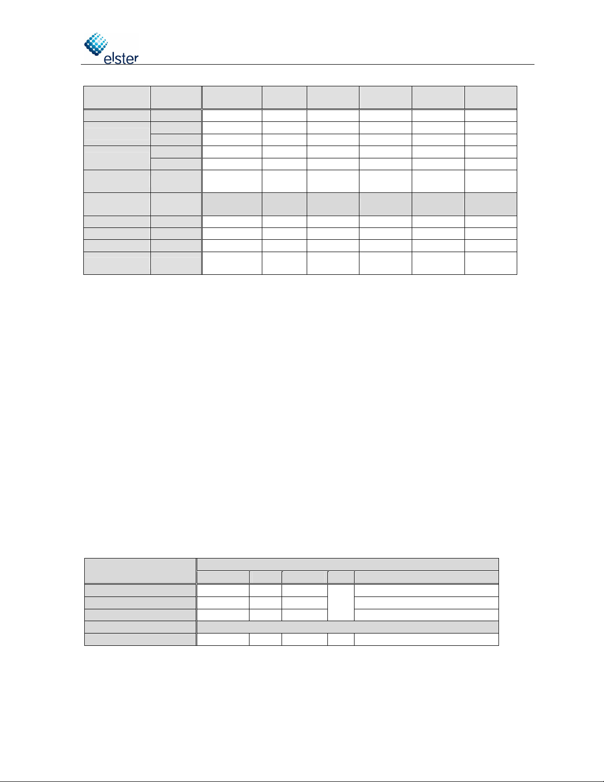
3 Wiring EK220/260/280
EM260
EK
terminal
Direction
of data
EM260
terminal
EK220 EK260
EK280
TxD TD TxD TxD
DTR RS RTS DTR
RxD RD RxD RxD
DCD CS CTS DCD
n.c.
RI
RI
RI
n.c. Gnd GND GND
Uext Uext + Uext + +9V
GND Uext - Uext - GND
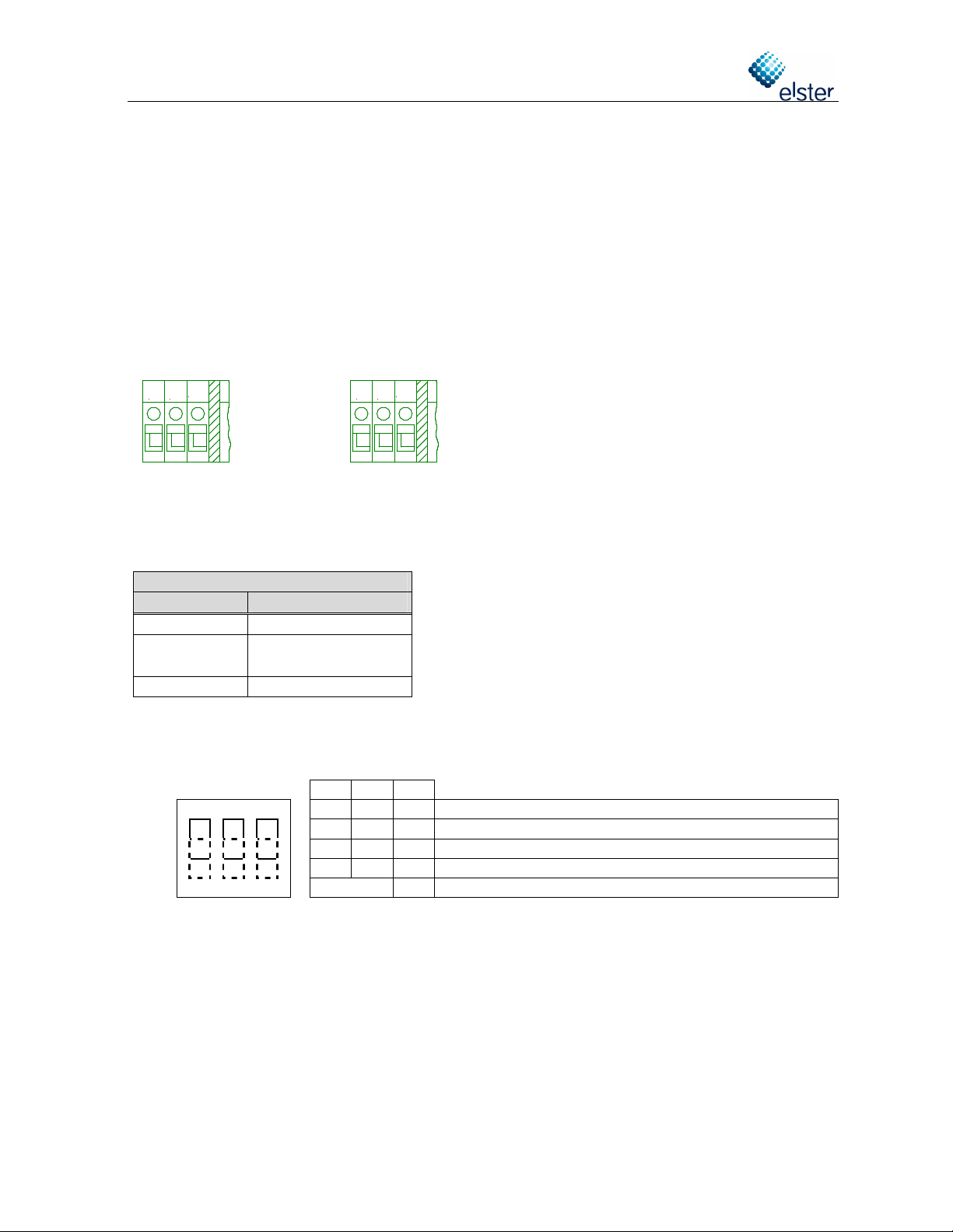
4 Wiring of EM260´s communication interface
If an analogue modem, an ISDN adapter or an Ethernet adapter is mounted inside the EM260,
the corresponding cable is also mounted by Elster-Instromet exworks. The cable is connected to
the terminals a(Rx-), b(Rx+), a2(Tx-) and b2(Tx+).
When using a CL0 interface, a shielded cable with two leads (e.g. ID no. 04250467, 2 x 1,0 mm
2
)
must be connected on site by the customer in the following way:
EM260 terminal
Terminal in the C
L1 modem
a (Rx-) CL- / Rx-
b (Rx+) CL+ / Rx+
5 Settings of the serial interface in the EK220/260/280
If the EK2x0 is delivered together with the EM260, the EK2x0´s internal serial interface as well as
the communication module integrated in the EM260 are properly set by Elster-Instromet exworks.
If the EM260 is delivered separately for additional installation beside an EK2x0, the internal serial
interface of the EK2x0 must be set in accordance with the software version of the EK2x0 and with
the type of communication module integrated in the EM260.
The serial interface of the EK2x0 must be parameterised before the EM260 is
connected to the EK2x0 and switched on.
For this purpose the parameter software “WinPADS200-EK“ or “enSuite” (only for EK280) can be
used:
- WinPADS200-EK: Menu “Data transfer”, item “Send parameter file…”
- enSuite: Item “Send parameter file”, then button “Open…”
Then you can select the parameter file (*.WPP) which fits to your application (communication
module, version of EK2x0).
Example:
EM260 with an analogue modem connected with an EK280 V2.0:
„EK280_2v2.. - EM260 & i-modul Analogmodem_a.WPP“
If there is no laptop with WinPADS or enSuite available on site, you can set the most important
values via the keypad of the EK2x0 (EK220/260: menu “Ser.IO”, EK280: menu “Terminal
Interface”).
The following values cannot be set via the keypad: SMS specific values, ISDN MSN, IP address
for Ethernet.
The following table contains the most important parameters which can be set via the interface
menu:
For the wiring, a shielded
8-wire cable
(Elster-Instromet ID no. 04250469) is
recommended. In the EM260 the cable
is assembled by Elster-Instromet
exworks. When connecting the EM260
to the EK2x0, please ensure the cable
is properly inserted into the EMV cable
fitting on the EK2x0.

Manual EM260
with Volume Corretor EK260/280
4 / 6 Betriebsanleitung-EM260-EK2x0_en_g.doc
Commun
ication
module
EK260
SW vers.
Md.S2
(2:705)
DF.S2
(2:707)
Bd.S2
(2:708)
-----
(2:709)
1)
TypS2
(2:70A)
Num.T
(2:720)
Analogue
4)
all
2
0
19200
19200
1
1,
2
…9
ISDN up to 2.3..
5 0 19200 19200 1 -
3)
from 2.4.. 2 0 19200 19200 1 1
Ethernet up to 2.3..
5 2 19200 19200 1 -
3)
from 2.4.. 2 2 19200 19200 1 1
CL from 2.0.. 5 0 od. 2
2)
300...
19200
2)
300...
19200
2)
1 -
3)
EK280
SW-Vers.
MdxS2
(2:706)
Analog ab 2.0.. standard AT
auto 19200 19200 RS232 1
ISDN ab 2.0.. standard AT
auto 19200 19200 RS232 1
Ethernet ab 2.0.. standard AT
auto 19200 19200 RS232 1
CL ab 2.0.. transparent auto 300...
19200
2)
300...
19200
2)
RS232 -
3)
1)
Not available in in the interface menu! Can only be modified with “WinPADS200-EK“ or “enSuite”!
2)
According to the settings in the CL1 modem and the other devices installed in the current loop (CL).
3)
This setting (number of rings) is not used in mode 5. In mode 5 the communication module in the EM260
always picks up an incoming call after the first ring signal.
4)
Numbers in bold: Exworks settings performed by Elster-Instromet if the EK2x0 is delivered without any
modem.
6 Setting the parameters for the communication module
The parameters for the communication module (modem) in the EM260 are set ex-works for use
with an EK2x0.
If the parameters have to be modified on site, this can be carried out with the help of the
parameter software “WinPADS200-EK“: Menu „File transfer…“, item “Send parameter file…”.
Then you can select the parameter file (*.WPP) which fits to your application (communication
module, version of EK2x0).
Example: EM260/Analogue modem with EK260 V2.55
“EK260_2v5.. - EM260 & int. Analog-Modem (Insys)_b.WPP“
Before disconnecting, the button “Init modem“ should be pressed (“Interface – Modem
initialisation“). after it is disconnected, the EK2x0 sends the parameters to the communication
module. The parameters are also sent after switching on the power supply and after “M.INI=1” in
EK2x0´s menu “Ser.IO”.
The parameterisation of the communication module does not work with all EK2x0 versions and
also not with all types of communication modules. The following table shows the dependences
(“x“ means: Communication module can be parameterised by the EK2x0):
Software version of
EK260
Remarks
Analogue ISDN
Ethernet
CL0
1.11
1)
1)
1)
2)
from V2.0.. up to V2.3..
x
1) 3)
1) 3)
from V2.4..
x
x
x
EK280
From 2.0.. x x x
2)
1)
Parameterisation can be carried out only by Elster-Instromet exworks or by Elster-Instromet customer
service on site with the help of the software tool “ModemIni“ (ID no. 73017249).
2)
CL0 interface need not be parameterised
3)
The modem parameters, of course, can be set by “WinPADS200-EK“ („Interface – String for connected
modem“), but after carrying out the parameterisation (Button „Init modem“, „M.INI=1“ or switching on
power supply) they must be deleted again!!! Otherwise the communication module will not pick up any
further incoming call!!!

Manual EM260
with Volume Corrector EK260/280
Betriebsanleitung-EM260-EK2x0_en_g.doc 5 of 6
7 Replacement of communication modules
A faulty communication module can be substituted by another communication module of the
same type by the customer on site. It depends on the software version of the EK2x0 and on the
type of the communication module if the new module can be parameterised on site or if it must be
parameterised by Elster-Instromet exworks (refer to the table in chapter 6).
The replacement of a communication module by another communication module of a different
type (e.g. analogue modem replaced by ISDN adapter) can only be carried out by Elster-
Instromet exworks or by Elster-Instromet´s customer service.
8 Power supply
The voltage required for power supply is marked on the nameplate (90...260 VAC / 18...30 VDC).
The three left screwing terminals are connected as follows:
90...260 VAC version: 18...30 VDC version:
~
~
PE
+
-
PE
9 Operating status display
Green LED: Power on
Yellow LED: Ring / Online
The yellow Online-LED has the following meanings:
Analogue Modem / ISDN / Ethernet
LED status Meaning
off no connection
flashing briefly
ringing signal
on online / data transfer
NB: when a CL interface is in use, the Online-LED is always off!!!
10 Jumper
J1
J2
J3
J1 J2 J3
up up up Analogue Modem / ISDN / Ethernet / CL
up
up down
up Reserved
down
up up Setting parameters for analogue modem / ISDN / Ethernet
down
down
down
up Reserved
any down
Reserved
.

Manual EM260
with Volume Corretor EK260/280
6 / 6 Betriebsanleitung-EM260-EK2x0_en_g.doc
11 Technical Data
•Internal communication module (only one of the following possibilities is integrated into the
EM260):
– Standard analogue modem: V.32bis (14.4 kbps)
– ISDN adapter: V.110, V.120, X.75, PPP, HDLC
– Ethernet-LAN adapter: 10base-T, 10Mbit/s.
– ELSTER-CL0 interface card
•RS232 / V.24 interface to the end device (RxD, TxD, Gnd, DCD, DTR, RI), galvanically
separated, screw terminals for leads with cross section 0.5...1.5 mm
2
•Power supply for EK2x0 and EK-88: output 8.5 VDC +/-5% / 50 mA, galvanically separated,
screw terminals for leads with cross section 0.5...1.5 mm
2
•5 VDC outputs for interface component of LIS100 devices, only switched on during modem
connection (online status), screw terminal for lead with cross section 0.5...1.5 mm
2
•Power supply:
– 90...260 VAC, L, N, PE
– 18...30 VDC, +, -, PE
– screw terminal for lead with cross section 0.5...1.5 mm
2
•Synthetic housing (standard ABS) with metallised surface inside, IP65 in accordance with
EN60529, EMV cable fitting for shielded cable, otherwise synthetic cable fittings
•Ambient temperature:
- with analogue modem ‘INSYS i-module-Modem’: 0 ... + 50 °C
- with ISDN adapter ‘TA+HUX’: 0 ... + 50 °C
- with CL interface (CL0, passive): -10 ...+ 60 °C
- with Ethernet card: 0 ...+ 50 °C
•Ambient humidity: max. 93%, non condensating
•Declaration of EU conformity in accordance with the current version of the EMC-Directive
89/336/EEC:
The product ‘EM260’ conforms to the current versions of the following standards:
Emission
EN 55011 Class B (for domestic and commercial applications)
Immunity EN 61326 (Electrical equipment for measurement, control and laboratory use)
EN 12405 (Volume correctors)
EN 55024 (IT equipment, data transmission devices)
Table of contents
Other Elster Modem manuals
Popular Modem manuals by other brands

QEI
QEI UG-1032 manual

Motorola
Motorola SURFboard SBG900 Specifications

Westell Technologies
Westell Technologies WIRESPEED B90-36R305 Installation and user guide

STMicroelectronics
STMicroelectronics UM2322 user manual

Skyroam
Skyroam Gmate Pluse user manual

TRENDnet
TRENDnet TFM-PCIV92A - DATA SHEETS Installation