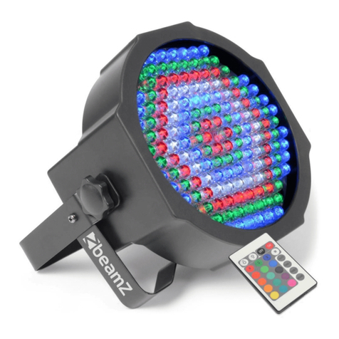
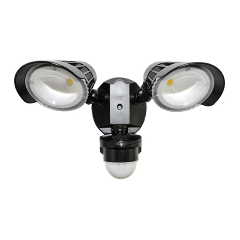
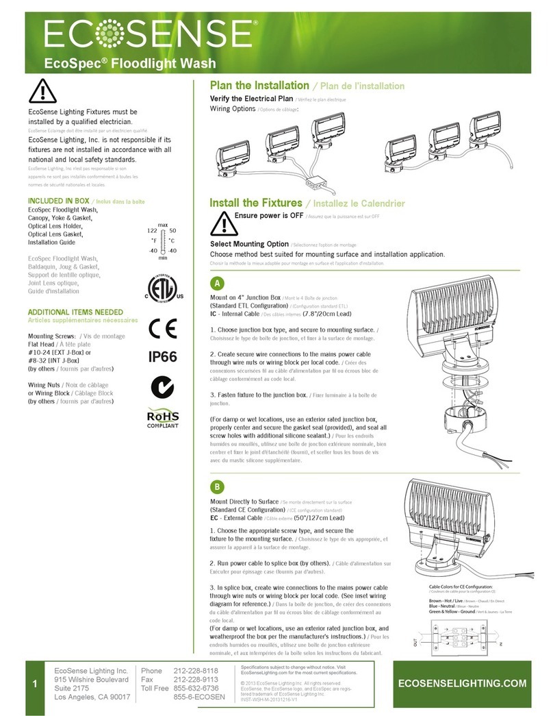
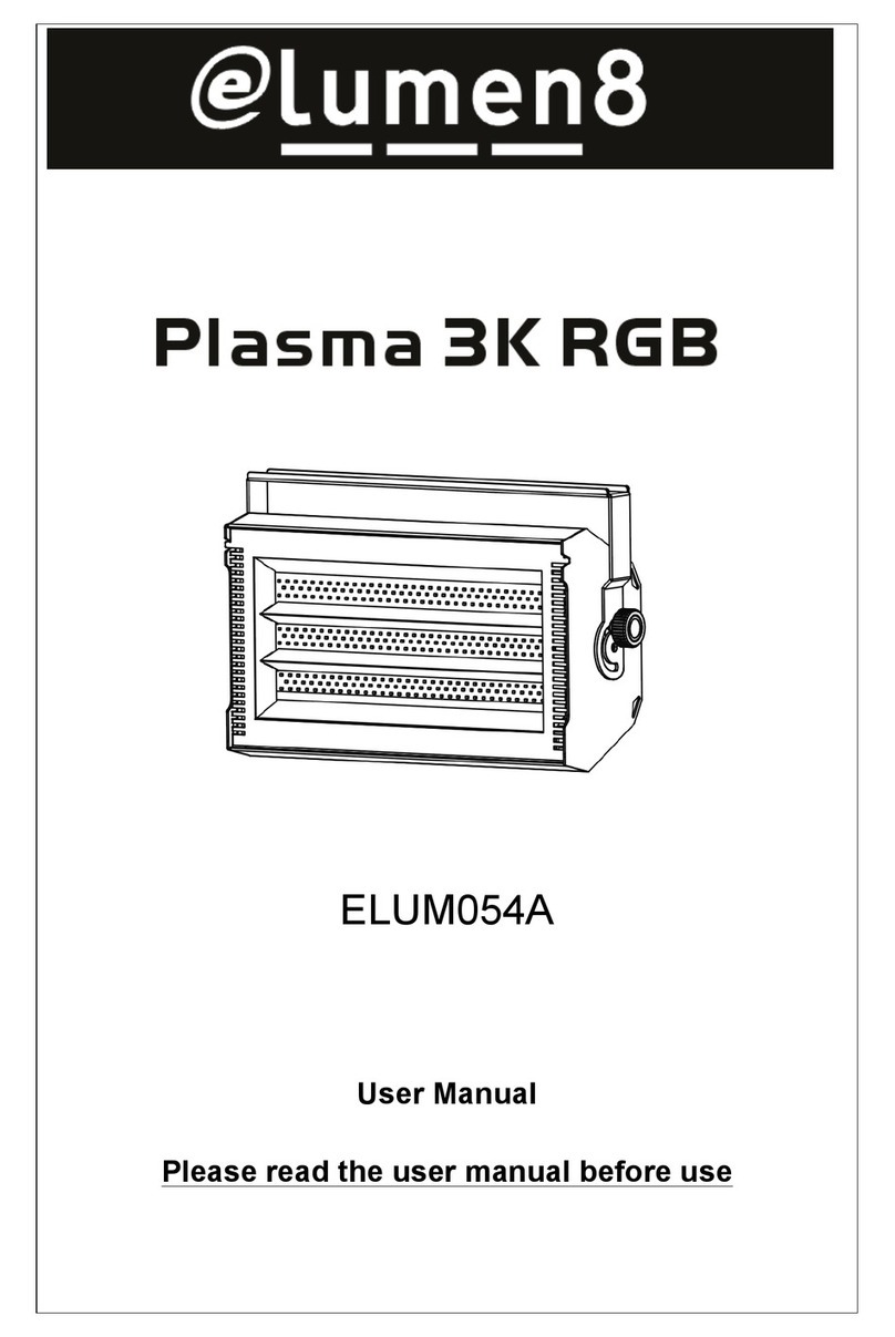
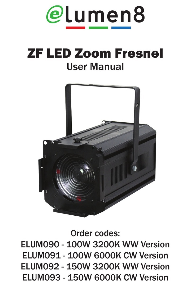
Elumen8 Alu Quad Par 64 User manual

Order code: ELUM113
Alu Quad Par 64
(18 x 8W RGBW/RGBA)
User Manual

www.prolight.co.uk Alu Quad Par 64 User Manual
2
Safety advice
WARNING
FOR YOUR OWN SAFETY, PLEASE READ THIS USER MANUAL
CAREFULLY BEFORE YOUR INITIAL START-UP!
• Beforeyourinitialstart-up,pleasemakesurethatthereisnodamagecausedduringtransportation.
• Shouldtherebeanydamage,consultyourdealeranddonotusetheequipment.
• Tomaintaintheequipmentingoodworkingconditionandtoensuresafeoperation,itisnecessary
fortheusertofollowthesafetyinstructionsandwarningnoteswritteninthismanual.
• Pleasenotethatdamagescausedbyusermodicationstothisequipmentarenotsubjecttowarranty.
IMPORTANT:
The manufacturer will not accept liability for any resulting damages caused by the non-observance
of this manual or any unauthorised modication to the equipment.
OPERATING DETERMINATIONS
Ifthisequipmentisoperatedinanyotherway,thanthosedescribedinthismanual,theproductmaysufferdamageand
thewarrantybecomesvoid.Incorrectoperationmayleadtodangere.g:short-circuit,burnsandelectricshocksetc.
Donotendangeryourownsafetyandthesafetyofothers!
Incorrectinstallationorusecancauseseriousdamagetopeopleand/orproperty.
• Neverletthepowercablecomeintocontactwithother
cables.Handlethepowercableandallmainsvoltage
connectionswithparticularcaution!
• Neverremovewarningorinformativelabelsfromtheunit.
• Donotopentheequipmentanddonotmodifytheunit.
• Donotconnectthisequipmenttoadimmerpack.
• Donotswitchtheequipmentonandoffinshortintervals,
asthiswillreducethesystem’slife.
• Onlyusetheequipmentindoors.
• Donotexposetoammablesources,liquidsorgases.
• Alwaysdisconnectthepowerfromthemainswhen
equipmentisnotinuseorbeforecleaning!Onlyhandle
thepower-cablebytheplug.Neverpullouttheplugby
pullingthepower-cable.
• Makesurethattheavailablevoltageisbetween
100~240V,50/60Hz.
• Makesurethatthepowercableisnevercrimpedor
damaged.Checktheequipmentandthepowercable
periodically.
• Iftheequipmentisdroppedordamaged,disconnectthe
mainspowersupplyimmediatelyandhaveaqualied
engineerinspecttheequipmentbeforeoperatingagain.
• Iftheequipmenthasbeenexposedtodrastic
temperatureuctuation(e.g.aftertransportation),
donotconnectpowerorswitchitonimmediately.
Thearisingcondensationmightdamagetheequipment.
Leavetheequipmentswitchedoffuntilithasreached
roomtemperature.
• Ifyourproductfailstofunctioncorrectly,stopuse
immediately.Packtheunitsecurely(preferablyinthe
originalpackingmaterial),andreturnittoyourProLight
dealerforservice.
• Onlyusefusesofsametypeandrating.
• Repairs,servicingandpowerconnectionmustonlybe
carriedoutbyaqualiedtechnician.THISUNITCONTAINS
NOUSERSERVICEABLEPARTS.
• WARRANTY:Oneyearfromdateofpurchase.
CAUTION!
KEEP THIS EQUIPMENT
AWAY FROM RAIN,
MOISTURE AND LIQUIDS
CAUTION!
TAKE CARE USING
THIS EQUIPMENT!
HIGH VOLTAGE-RISK
OF ELECTRIC SHOCK!!
www.prolight.co.uk Alu Quad Par 64 User Manual
3
Product overview & technical specications
TheAluQuadfeatures18x8Wquad-colourLEDs(12xRGBW,
6xRGBA),sinceeachindividualLEDincorporatesaRGBW
orRGBAchipbehindasinglelens,shadowsandunevenness
withintheeldarethingsofthepast.
Housedinsidetheruggedcastaluminiumchassisisan
advancedLEDcontrolpanelgivingtheabilitytorunbuilt-in
programsandperformfullRGBW/RGBAcolourmixingwith
orwithoutDMXcontrol.
•2yearwarranty
•18x8Wquad-colourLEDs(12xRGBW+6xRGBA)
•Beamangle:25°
•400Hzrefreshrate
•DMXchannels:3/5/7or8selectable
•Staticcolour,colourchange,colourfade,auto,
soundactiveandmaster/slavemodes
•0-100%dimmingandvariablestrobe
•3pushbuttonmenuwithLEDdisplay
•3-pinXLRin/outsockets
•PowerCONin/outsockets
•Fancooled
•OptionalBarnDoors(ELUM041C)
Alu Quad Par 64
Specications Alu Quad Par 64
Powerconsumption 163W
Powersupply 100~240V,50/60Hz
Dimensions 300x270x222mm
Weight 4.3kg
Ordercode ELUM113
0m 1m 2m 3m 4m 5m
25° - Lux 14400 3800 1850
25°
960 615
300mm
270mm

www.prolight.co.uk Alu Quad Par 64 User Manual
4
DMX channel mode:
OperatinginDMXcontrolmodegivestheuserthegreatestexibilitywhenitcomestocustomising
orcreatingashow.Inthismodeyouwillbeabletocontroleachindividualtraitofthextureandeach
xtureindependently.
ToaccesstheDMXchannelmode,pressthe“MODE”buttonontherearoftheunittoshow3CH
ontheLEDdisplay,thenusethe“UP”and“DOWN”buttonstosetthedesiredDMXaddressofeither
3,5,7or8DMXchannelmodes.
Tosettheunitsaddress,pressthe“MODE”buttonontherearoftheunittoshow001onthe
LEDdisplay,thenusethe“UP”and“DOWN”buttonstosetthedesiredaddressfrom 001 ~ 512.
Technical specications
Operating instructions
01-Bracket
02-Brackettighteningknobs
03-Earthpoint
04-Safetyeye
05-LEDdisplay
06-Functionbuttons
07-DMXinputsocket
08-DMXoutputsocket
09-PowerCONinsocket
10-PowerCONoutsocket
11-Fuse2A240V
Inthebox:1 x xture,
1 x 13A powerCON
mains cable &
1 x user manual
MODE UPDOWN
PUSH
www.prolight.co.uk
FUSE
2A/250V
SAFETY
EYE
DMX
IN
DMX
OUT
POWER IN POWER OUT
ALU QUAD
PAR 64
06 040611
03 09 07 08 10
0102
Channel Value Function
1000-007 Blackout
008-255 30presetstaticcolours
2000-255 Masterdimmer0-100%
3001-005 Soundmode
006-010 On
011-255 Strobe(slowtofast)
Channel Value Function
1000-255 Red(0-100%)
2000-255 Green(0-100%)
3000-255 Blue(0-100%)
4000-255 Amber(0-100%)
5 000-255 White(0-100%)
3 channel mode: 5 channel mode:

www.prolight.co.uk Alu Quad Par 64 User Manual
5
Master/slave mode
Tosetthemasterunit,pressthe“MODE”buttonontherearofthemasterunitthenselectyour
desiredprogram.Tosetinslavemode,pressthe“MODE”buttonontherearoftheunitandsetthe
addresstoshow 001ontheLEDdisplay.Theunitwillnowruninsequencewiththemasterunit.
Sound active mode:
Toaccessthesoundactivemode,pressthe“MODE”buttonontherearoftheunittoshow S01
ontheLEDdisplay.Theunitwillnowbeinsoundactivemode.Nowusethe“UP”and“DOWN”buttons
tosetthesoundsensitivitylevelfrom S00 ~ S99(00 = low, 99 = high).
Note: The higher the value the more sensitive it will be, and is set to S50 as default.
Static colour mode:
Toaccessthestaticcolourmode,pressthe“MODE”buttontoshow C01ontherearoftheunit.
Nowusethe“UP”and“DOWN”buttonstoselectoneofthe30staticcolours.
Built-in programs mode
Toaccessthebuilt-inprogramsmode,pressthe“MODE”buttonontherearoftheunittoshowP01
ontheLEDdisplay.Nowusethe“UP”and“DOWN”buttonstoselectbetweenthe6built-inprograms.
Operating instructions
Channel Value Function
1000-255 Red(0-100%)
2000-255 Green(0-100%)
3000-255 Blue(0-100%)
4000-255 Amber(0-100%)
5 000-255 White(0-100%)
6 000-255 Masterdimmer(0-100%)
70On
001-005 Soundmode(7colours)
006-010 On
011-255 Strobe(slowtofast)
Channel Value Function
1000-255 Red(0-100%)
2000-255 Green(0-100%)
3000-255 Blue(0-100%)
4000-255 Amber(0-100%)
5 000-255 Red(0-100%)
6 000-255 Green(0-100%)
7 000-255 Blue(0-100%)
8 000-255 White(0-100%)
Mode Operation
15colourchange,every3seconds
230colourchange,every3seconds
35colourfade,every3seconds
430colourfade,every3seconds
5 5colourchangeviasound
6 30colourchangeviasound
7 channel mode: 8 channel mode:

www.prolight.co.uk Alu Quad Par 64 User Manual
6
Setting the DMX address:
TheDMXmodeenablestheuseofauniversalDMXcontroller.Eachxturerequiresa“startaddress”
from1-511.Axturerequiringoneormorechannelsforcontrolbeginstoreadthedataonthechannel
indicatedbythestartaddress.Forexample,axturethatoccupiesoruses7channelsofDMXandwas
addressedtostartonDMXchannel100,wouldreaddatafromchannels:100,101,102,103,104,105
and106.Chooseastartaddresssothatthechannelsuseddonotoverlap.E.g.thenextunitinthe
chainstartsat107.
DMX 512:
DMX(DigitalMultiplex)isauniversalprotocolusedasaformofcommunicationbetweenintelligent
xturesandcontrollers.ADMXcontrollersendsDMXdatainstructionsformthecontrollertothexture.
DMXdataissentasserialdatathattravelsfromxturetoxtureviatheDATA“IN”andDATA“OUT”
XLRterminalslocatedonallDMXxtures(mostcontrollersonlyhaveadata“out”terminal).
DMX linking:
DMXisalanguageallowingallmakesandmodelsofdifferentmanufacturestobelinkedtogether
andoperatefromasinglecontroller,aslongasallxturesandthecontrollerareDMXcompliant.
ToensureproperDMXdatatransmission,whenusingseveralDMXxturestrytousetheshortest
cablepathpossible.TheorderinwhichxturesareconnectedinaDMXlinedoesnotinuencethe
DMXaddressing.Forexample;axtureassignedtoaDMXaddressof1maybeplacedanywherein
aDMXline,atthebeginning,attheend,oranywhereinthemiddle.Whenaxtureisassigneda
DMXaddressof1,theDMXcontrollerknowstosendDATAassignedtoaddress1tothatunit,
nomatterwhereitislocatedintheDMXchain.
DATA cable (DMX cable) requirements (for DMX operation):
ThisxturecanbecontrolledviaDMX-512protocol.TheDMXaddressissetonthebackoftheunit.
YourunitandyourDMXcontrollerrequireastandard3-pinXLRconnectorfordatainput/output,
seeimagebelow.
Note: DMX cable must be daisy chained and cannot be split.
DMX setup
FurtherDMXcablescanbe
purchasedfromallgoodsound
andlightingsuppliersor
ProLightConceptsdealers.
Pleasequote:
CABL10 – 2m
CABL11 – 5m
CABL12 – 10m

www.prolight.co.uk Alu Quad Par 64 User Manual
7
Notice:
Besuretofollowthediagramsbelowwhenmakingyourowncables.Donotconnectthecables
shieldconductortothegroundlugorallowtheshieldconductortocomeincontactwiththeXLRs
outercasing.Groundingtheshieldcouldcauseashortcircuitanderraticbehaviour.
Special note:
Line termination:
Whenlongerrunsofcableareused,
youmayneedtouseaterminatoron
thelastunittoavoiderraticbehaviour.
Using a cable terminator will decrease
the possibilities of erratic behaviour.
(3-pin - Order ref: CABL90, 5-pin - Order ref: CABL89)
5-pin XLR DMX connectors:
Somemanufacturesuse5-pinXLRconnectorsfordatatransmissioninplaceof3-pin.5-pinXLRxtures
maybeimplementedina3-pinXLRDMXline.Wheninsertingstandard5-pinXLRconnectorsintoa
3-pinlineacableadaptormustbeused.Thediagrambelowdetailsthecorrectcableconversion.
Terminationreducessignaltransmission
problemsandinterference.Itisalways
advisabletoconnectaDMXterminal,
(resistance120Ohm1/4W)betweenpin2
(DMX-)andpin3(DMX+)ofthelastxture.
5-pin XLR (socket)
Pin 1: GND (screen)
Pin 2: Signal (-)
Pin 3: Signal (+)
Pin 4: N/C
Pin 5: N/C
3-pin XLR (socket)
Pin 1: GND (screen)
Pin 2: Signal (-)
Pin 3: Signal (+)
3-pin XLR (socket)
Pin 1: GND (screen)
Pin 2: Signal (-)
Pin 3: Signal (+)
5-pin XLR (socket)
Pin 1: GND (screen)
Pin 2: Signal (-)
Pin 3: Signal (+)
Pin 4: N/C
Pin 5: N/C
DMX setup

www.prolight.co.uk Alu Quad Par 64 User Manual
8
Optional accessories & WEEE notice
Correct Disposal of this Product
(Waste Electrical & Electronic Equipment)
(Applicable in the European Union and other European countries
with separate collection systems)
Thismarkingshownontheproductoritsliterature,indicatesthatitshouldnotbedisposed
withotherhouseholdwastesattheendofitsworkinglife.Topreventpossibleharmtothe
environmentorhumanhealthfromuncontrolledwastedisposal,pleaseseparatethisfromother
typesofwastesandrecycleitresponsiblytopromotethesustainablereuseofmaterialresources.
Householdusersshouldcontacteithertheretailerwheretheypurchasedthisproduct,ortheir
localgovernmentofce,fordetailsofwhereandhowtheycantakethisitemforenvironmentally
saferecycling.
Businessusersshouldcontacttheirsupplierandcheckthetermsandconditionsofthe
purchasecontract.Thisproductshouldnotbemixedwithothercommercialwastesfordisposal.
Pleasecontactyourlocalretailertopurchasetheseaccessories.
Optional eLumen8 Alu Tri Barn Door
Order code: ELUM041C
Optional LEDJ Alu Par 64 Series
Floor Bracket
Order Code - LEDJ119
Optional Cases
Order codes: Twin - CASE17
Twin - CASE16
Tokeepup-to-dateonthelatestaccessoriesandproduct
rangeadditionspleasevisitwww.prolight.co.uk
Other manuals for Alu Quad Par 64
1
Table of contents
Other Elumen8 Floodlight manuals

Elumen8
Elumen8 ELUM062 User manual

Elumen8
Elumen8 ELUM042 User manual

Elumen8
Elumen8 Endura WW100 User manual

Elumen8
Elumen8 Alu Quad Par 64 User manual

Elumen8
Elumen8 ELUM054A Plasma 3K RGB User manual

Elumen8
Elumen8 ELUM053 User manual

Elumen8
Elumen8 Tri Pixel Panel 25 ELUM085 User manual

Elumen8
Elumen8 ZF LED Zoom Fresnel ELUM090 User manual

Elumen8
Elumen8 Beam 1RE User manual

Elumen8
Elumen8 Stage Par 220 User manual