Elvox Digibus Galileo Series Guide

MODULES FOR ELECTRONIC VIDEO OR AUDIO ENTRANCE PANEL WITH KEYPAD
AND NUMERICAL DISPLAY
INSTALLATION AND CONNECTION MANUAL
ART. 8942
GB
ART. 8946
ART. 8946/C
Cod. S6I.894.20E Ed. 03 7/2006
Product is according to EC Directive 89/336/EEC and following norms.

FOREWORD
The Galileo series of Digibus electronic entrance panels is designed to operate both on DigiBus systems with 4-digit codes (old type) and on
DigiBus systems with 8-digit codes (new type). Operation with 4-digit codes is recommended only for existing installations which use this cod-
ing system, otherwise use the 8-digit codes for new installations, regardless of the number of internal units. The parameter which determines
the type of code is the number 8 "Digit Number" (see table on page 15). The elements which make up the Galileo series of entrance panels
make it possible to execute different types of panel according to the components selected and assembled.
The following parts are required for assembly of the entrance panels: basic electronic modules, any supplementary modules, module holder
frames for electronic entrance panels, flush-mounted or surface-mounted wall boxes, bezels or frames with rainproof cover. The choice of parts
depends on the model of entrance panel and its dimensions.
Selecting the parts starts with: the basic electronic modules, supplied in packs of three, which determine the model of entrance panel (audio
panel with keypad and numerical display, video panel with keypad and numerical display, audio panel with conventional pushbuttons, video
panel with conventional pushbuttons). It continues with the addition of any supplementary modules for expanding the basic modules, and is fol-
lowed by selection of the module holder frames for assembling the modules. Lastly, to complete the entrance panel, you select the version of
box and frame according to the type of panel installation i.e. flush or surface wall mounting).
DESCRIPTION
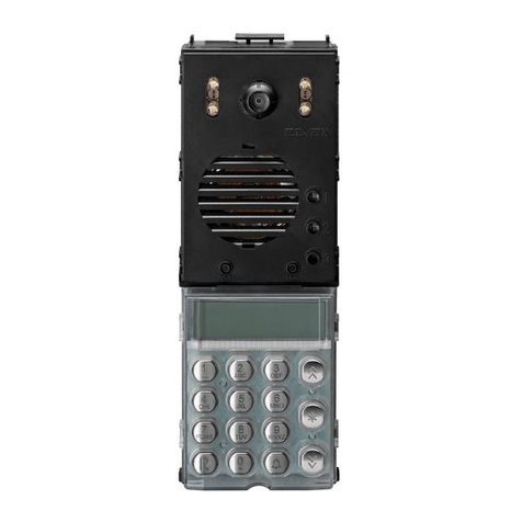
Articles 8942, 8946, 8946/C correspond to 3 packs of 3 modules respectively, each for the composition of 3 models of electronic panel : elec-
tronic audio panel with keypad and numerical display (Art. 8942), electronic video panel with B/W camera and keypad and numerical display
(art. 8946), electronic video panel with colour camera and keypad and numerical display (art. 8946/C).
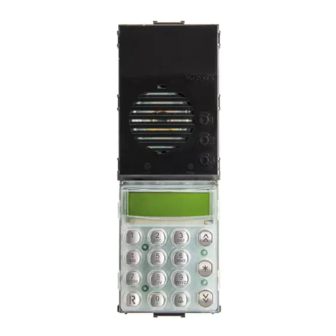
The electronic entrance panels have the capability of generating 99999999 digital calls with different codes by means of the 15-key keypad
supplied with the panels. The dialled number between 1 and 99999999 is shown on a display and sent to the interphones by pressing the "C"
key. The "R" key is used for cancelling the operation. The panels are set up to operate either alone or in conjunction with other panels and
switchboards by suitably connecting the pull-out terminal blocks located on the back of the panels themselves. As well as the connection ter-
minal block, the back of the panel also accommodates the "External Volume - P1", "Internal Volume - P3" and "Balance - P2" controls, which
are factory-set. If necessary, you are advised to adjust only the "External Volume" and, if appropriate, the "Balance" in the case of feedback on
the speech unit, by slowly turning the trimmer in one direction or the other until the whistling stops. The entrance panels are supplied with back-
lit (with LEDs) name-tag modules in versions for 13 users. For programming the technical parameters, the panel can also be interfaced with
the programmer art. 950B or with a Personal Computer using the software art. 94CT and interface 6952.
INSTALLATION
Assembly and installation of the Galileo electronic entrance panels involves the following phases:
1 - Defining the basic modules and supplementary modules.
2 - Defining the module holder frames (art. 8D81, 8D82, 8D83 or 8D84) according to the modules to be joined.
3 - Defining the boxes and frames for flush or surface wall mounting.
4 - Fitting the electronic modules inside the module holder frames.
5 - Wiring the modules.
7 - Installing the flush or surface-mounted wall box at a height of approximately
1.65 m measured between the top edge of the box and the ground. Use the
hole drilled in the bottom of the box to insert the wires.
8 - Connect the entrance panel to the system as illustrated in the wiring dia-
grams.
9 - Cut the ON-OFF jumper adjacent to the terminal block only if indicated in the
wiring diagram.
10 -Fix the entrance panel microphone on the bottom end fixing element.
11 -Close the panel.
12 -Programme the entrance panel if necessary: programming
"Technical Parameters".
DESCRIPTION
2

MODULES Art. 8942
Art. 8942 is a pack containing 3 basic electronic modules for executing an audio entrance panel with keypad and numerical display with 8 dig-
its. The three modules are: one audio module, one module with display and numerical keypad and one name-tag module for 13 names, with
terminal blocks for connecting the panel.
COMPONENTS
R
88888888
R
TO TERMINAL
BLOCK MODULE
5431V
MCH 8 6 V2 M V1
Art. 8A09 Art. 8A15 Art. 8A0N
MODULES Art. 8946 and 8946/C
Art. 8946 and 8946/C are packs containing 3 basic electronic modules for executing video entrance panels with keypad and 8-digit numerical
display. The modules are: one audio/video module with camera, one module with display and numerical keypad and one name-tag module for
13 names, with terminal block for connecting the panel. Art. 8946 uses one B/W camera with ¼" CCD sensor (white light LED) and fixed 3 mm
lens (infrared LED lighting), whereas article 8946/C uses one colour camera with ¼" CCD sensor and 3 mm fixed lens.
BACK OF MODULES
CN2 CN1
Made in ITALY
RR
ART.8A09
ART.8A19
VOLUME
ESTERNO
-
BILANC. VOLUME
INTERNO
EXTERNAL
VOLUME
AUDIO
BALANCE INTERNAL
VOLUME
P1 P2 P3
++--
+
PS2
PS1
RESET
Made in ITALY
RR
CN4
CN3
PROGRAM
CN1
ART.8A15
CODING FOR RESIDENTIAL ESTATE
CODIFICA PER COMPLESSO EDILIZIO
LOWER CODE OF USER
NUMERO MINIMO UTENTE
UPPER CODE OF USER
NUMERO MASSIMO UTENTE
TO TERMINAL
BLOCK MODULE
5431V
MCH 8 6 V2 M V1
CN2
ON
OFF
INITIAL PUSH-BUTTON CODE
CODICE PULSANTE INIZIALE
F2
F1
+L
+I
S
ART.8A6_
ART.8A2_
ART.8A0N
TO TERMINAL
BLOCK MODULE
P5
CORR.
GEN.
made in ITALY
R
Electronic module with numerical keypad
and 8-digit display.
The following elements are located on the
back of the panel: -
- PS1 RESET button.
- PS2 input button for programming- CN1
connector for connecting module art.
8A09 or 8A19 or 8A19/C with wiring
CN1.
- Connector CN4 for connecting pro-
grammer art. 950B.
- Connector CN3 not used.
- PROGRAM connector for “software”
updating.
Art. 8A09, 8A19, 8A19/C Art. 8A15 Art. 8A0N
Electronic module with LED back-lit
name-tag holder (for 13 names). For
description of terminals, see page 34
appendix A. The following elements are
located on the back of the panel:
- CN2 connector for connecting module
art. 8A09 or 8A19 or 8A19/C with CN2
wiring.
- P5 current generator control
(typical value 25mA) - Terminal blocks
for connecting the entrance panel to
the system.
- ON/OFF jumper for activating/ disacti-
vating the current generator (ON =
jumper connected, OFF = jumper inter-
rupted).
Electronic audio module with speech unit. The
following controls are located on the back of the
panel:
- P1 external volume control (speaker).
- P2 external/internal audio volume balance.
- P3 internal volume control (microphone).
- CN1 wiring for connecting the module art.
8A15 with the connector CN1.
- CN2 wiring for connecting the module art.
8A0N with connector CN2.
- Microphone (to be fixed to the bottom end fix-
ing element of the frames 8D81, 8D82, 8D83
or 8D84).
R
88888888
R
TO TERMINAL
BLOCK MODULE
5431V
MCH 8 6 V2 M V1
Art. 8A19
Art. 8A19/C
Art. 8A15 Art. 8A0N
3

R
Supplementary module with LED back-lit name-tag holder (for 13 names), to be added to the
basic electronic modules for expansion of the entrance panel.
The back of the panel accommodates the two terminals LA (negative) and LB (positive) for pow-
ering the LEDs, to be connected as shown in the wiring diagrams.
SUPPLEMENTARY MODULE Art. 8A1N
R
Neutral supplementary module, to be added to the electronic modules to complete the entrance panel.
SUPPLEMENTARY MODULE Art. 8000
COMPONENTS
ART.8A1N
LA
LB
Made in ITALY
RR
EXTRACTING THE NAME-TAG HOLDER ON MODULES 8A0N AND 8A1N
4
A
Fig. 2 - At the back of the panel, remove the box of
the module by pressing the sides of the
box.
Fig. 3 - Use a screwdriver to remove the name-tag
fixing element.
Fig 1
Fig 2
Fig 3

ACCESSORIES: MODULE HOLDER FRAMES
Art. 8D81
Art. 8D82
Art. 8D83
Art. 8D84
Art. 9091
Art. 9092
Art. 9093
Art. 9094
ACCESSORIES: FLUSH-MOUNTED BACK BOXES
COMPONENTS
5
Thickness
21 mm
1 horizontal module
(width 101 mm)
No. vertical
modules (height)
Thickness
50 mm
No. vertical
modules
(height)
1 horizontal mod-
ule (width 88 mm)
1 module
(159 mm)
2 module
(271 mm)
3 module
(383 mm)
4 module
(495 mm)
1 module
(145 mm)
2 modules
(271 mm)
3 modules
(383 mm)
4 modules
(481 mm)

Art. 9111 Art. 9121 Art. 9131 Art. 9141
Art. 9112 Art. 9122 Art. 9132 Art. 9142
Art. 9113 Art. 9123 Art. 9133 Art. 9143
Art. 9114 Art. 9124 Art. 9134 Art. 9144
ACCESSORI: BEZELS
COMPONENTS
6
Thickness
2 mm
No. horizontal modules (width) No. Vertical modules (height)
1 module
(108 mm)
2 modules
(208 mm)
3 modules
(308 mm)
4 modules
(408 mm)
No. Vertical
modules
(height)
1 module
(169 mm)
2 modules
(281 mm)
3 modules
(393 mm)
4 modules
(505 mm)

Art. 9211 Art. 9221 Art. 9231 Art. 9241
Art. 9212 Art. 9222 Art. 9232 Art. 9242
Art. 9213 Art. 9223 Art. 9233 Art. 9243
Art. 9214 Art. 9224 Art. 9234 Art. 9244
ACCESSORIES: FRAMES WITH RAINPROOF COVER
COMPONENTS
7
Thickness
38 mm
No. horizontal modules (width)
1 module
(118 mm)
2 modules
(218 mm)
3 modules
(318 mm)
4 modules
(418 mm)
No. Vertical
modules
(height)
1 module
(178 mm)
2 modules
(290 mm)
3 modules
(402 mm)
4 modules
(514 mm)

8
Art. 9411 Art. 9421 Art. 9431 Art. 9441
Art. 9412 Art. 9422 Art. 9432 Art. 9442
Art. 9413 Art. 9423 Art. 9433 Art. 9443
Art. 9414 Art. 9424 Art. 9434 Art. 9444
ACCESSORIES: SURFACE-MOUNTED WALL BOXES
COMPONENTS
Thickness
50 mm 1 module
(118 mm)
2 modules
(218 mm)
3 modules
(318 mm)
4 modules
(418 mm)
No. horizontal modules (width) No. Vertical
modules
(height)
1 module
(178 mm)
2 modules
(290 mm)
3 modules
(402 mm)
4 modules
(514 mm)

9
FITTING THE MODULES IN THE MODULE HOLDER FRAMES
- Open the module holder frame by inserting a screwdriver in the two slits in the back of the bottom end fixing element (fig. 1A and 1B).
- Remove the bottom end fixing element (fig. 2). - Fit the modules in the module holder frame and the plate of the module with the name-tag
holder. On module holders 8D82, 8D83 and 8D84, fit the spacer between the modules (fig. 3A). Fit the bottom end fixing element in the
module holder frame (fig. 3B).
- In the back of the name-tag holder, fit the module box with the terminal blocks (fig. 4). Fit the RH clips of the box under the RH side-mem-
ber of the frame and, while pressing the box, fit the LH clips under the LH side-member (part A).
- Example of an assembled entrance panel (fig. 5).
Fig 1A
Fig 2
Fig 3B
Fig 3A
Fig 1B
Fig 4
Fig 5
ASSEMBLY
A

10
Fig 7A
Fig 6
ASSEMBLY
INSTALLING THE FLUSH-MOUNTED WALL PANEL WITH
OR WITHOUT BEZELS
To install the flush-mounted wall panel you need flush-mounted back
boxes art. 9091, 9092, 9093 or 9094 for 1, 2, 3 or 4 modules respec-
tively. If the entrance panel is made with more than one back box it
is necessary to use bezels (series 91xx) or frames with rainproof
cover (series 92xx) according to the number of modules disposed
vertically and horizontally.
Installation:
- If installation requires a combination of more than one box, use
the clips supplied with the boxes to fix them together (fig. 6).
- If you do not use the bezels, mount the boxes on the wall and fas-
ten onto them the end fixing elements supplied with the module
holder frames art. 8D81, 8D82, 8D83 and 8D84. Use the screws
supplied with the end fixing elements to fix them (fig. 7A - 8A).
If using the bezels: mount the boxes on the wall, place the series
91xx or 92xx bezel on top of the back boxes (fig. 7B - 7C), and
join the bezel to the boxes using the end fixing elements supplied
with module frame holders art. 8D81, 8D82, 8D83 and 8D84. Use
the screws supplied with the end fixing elements to fix the whole
assembly without tightening the screws, leaving a slight clear-
ance between the boxes and the frame (fig. 8B -8C).
- Fix the terminal block of module 8A0N to the bottom of the back
box using the adhesive supplied with the terminal block. Position
the terminal block on the bottom edge of the box into which the
wires are routed (part A, fig. 9A - 9B - 9C).
- If using the bezels, route the flat cables which join the modules
between the boxes and the bezels (fig. 10A - 10B - 10C). - Fix the
microphone of module art. 8A09 or 8A19 or 8A19/C onto the bot-
tom end fixing element of the frame, taking into account the fur-
thest bottom end fixing element to enable wiring of the micro-
phone. The RH side of the end fixing element has two plates onto
which to fit the microphone. With the bezels, route the wires of the
microphone between the boxes and the bezels (fig. 9A - 9B - 9C).
- If using the bezels, tighten the screws joining the end fixing ele-
ments to the bezel and the boxes.
- Fasten the plates to the end fixing elements and fix them using
the special ELVOX wrenches (fig. 10A - 10B - 10C).
Fig 8A
TOTERMINAL
BLOCKMODULE
5431V
MCH 8 6 V2 M V1
123
456
789
R0C
Fig 9A
Fig 10A
A
Fig 9D

ASSEMBLY
11
Fig 8B
TOTERMINAL
BLOCKMODULE
5431V
MCH 8 6 V2 M V1
Fig 7C
TOTERMINAL
BLOCKMODULE
5431V
MCH 8 6 V2 M V1
123
456
789
R0C
123
456
789
R0C
Fig 7B
Fig 8C
Fig 9B Fig 9C
Fig 10B Fig 10C
AA

ASSEMBLY
12
Fig 12
Fig 11
INSTALLING SURFACE WALL-MOUNTED PANELS
WITH RAINPROOF COVER
To install a surface wall-mounted panel you need to use the series
94xx surface-mounted wall box and series 92xx bezels with rainproof
cover, according to the number of vertically and horizontally arranged
modules.
Installation:
- Fix the surface-mounted box to the wall (fig. 11).
- Place the series 92xx bezel with rainproof cover on top of the box
(fig. 12).
- Fix the bezel to the box by means of the end fixing elements sup-
plied with the module holder frames art. 8D81, 8D82, 8D83 and
8D84. Use the fixing screws and pins (supplied with the frames) to
fix the end fixing elements to the box and bezel (fig. 12 - 13).
- Fix the terminal block of module 8A0N to the bottom of the box,
fastening it on the profile of the box (fig. 16). Position the terminal
block on the bottom edge of the box next to the wire inlet (part A,
fig. 14).
- Fix the microphone of module art. 8A09 or 8A19 or 8A19/C to the
bottom end fixing element of the frame (fig. 14), taking into
account the furthest bottom end fixing element to enable
wiring of the microphone. The RH side of the end fixing element
has two plates on which to fit the microphone.
- Route the flat cables joining the modules between the boxes and
the bezels. Fasten the plates to the end fixing elements and fix
them using the special ELVOX wrenches (fig. 15).
Fig 14
TOTERMINAL
BLOCKMODULE
5431V
MCH 8 6 V2 M V1
123
456
789
R0C
Fig 13
Fig 15
Fig 16
A

13
WIRING THE MODULES
Connect module art. 8A09 or 8A19 or 8A19/C to module 8A15, by means of the flat cable and connector CN1 (Fig. 17-18).
Connect module art. 8A0N to module 8A09 or 8A19 or 8A19/C, by means of the flat cable and connector CN2 (Fig. 17-18).
The supplementary modules art. 8A1N are to be connected directly to the power supply units as shown in the wiring diagrams (Fig. 18).
To disconnect the terminal block from module 8A0N, press the connector and extract the cable (see fig. 19).
Art. 8A15
Art. 8A0N
Art. 8A1N
Art. 8A09
or
Art. 8A19
or
Art. 8A19/C
CN2 CN1
Made in ITALY
R
ART.8A09
ART.8A19
VOLUME
ESTERNO
-
BILANC. VOLUME
INTERNO
EXTERNAL
VOLUME
AUDIO
BALANCE INTERNAL
VOLUME
P1 P2 P3
++--
+
TO TERMINAL
BLOCK MODULE
5431V
MCH 86V2 M V1
CN2
ON
OFF
INITIAL PUSH-BUTTON CODE
CODICE PULSANTE INIZIALE
ART.8A6_
ART.8A2_
ART.8A0N
TO TERMINAL
BLOCK MODULE
P5
CORR.
GEN.
made in ITALY
R
PS2PS1
RESET
Made in ITALY
R
CN4
CN3
PROGRAM
CN1
ART.8A15
CODING FOR RESIDENTIAL ESTATE
CODIFICA PER COMPLESSO EDILIZIO
LOWER CODE OF USER
NUMERO MINIMO UTENTE
UPPER CODE OF USER
NUMERO MASSIMO UTENTE
ART.8A1N
LA
LB
Made in ITALY
R
CN2 CN1
Made in ITALY
R
ART.8A09
ART.8A19
VOLUME
ESTERNO
-
BILANC. VOLUME
INTERNO
EXTERNAL
VOLUME
AUDIO
BALANCE INTERNAL
VOLUME
P1 P2 P3
++- - +
TO TERMINAL
BLOCK MODULE
5
4
3
1
V
M
CH V2 V1
CN2
ON
OFF
INITIAL PUSH-BUTTON CODE
CODICE PULSANTE INIZIALE
F2
F1
+L
+I
S
ART.8A6_
ART.8A2_
ART.8A0N
TO TERMINAL
BLOCK MODULE
P5
CORR.
GEN.
made in ITALY
R
PS2
PS1
RESET
Made in ITALY
R
CN4
CN3
PROGRAM
CN1
ART.8A15
CODING FOR RESIDENTIAL ESTATE
CODIFICA PER COMPLESSO EDILIZIO
LOWER CODE OF USER
NUMERO MINIMO UTENTE
UPPER CODE OF USER
NUMERO MASSIMO UTENTE
8M
6
CN2 CN1
Made in ITALY
R
ART.8A09
ART.8A19
VOLUME
ESTERNO
-
BILANC. VOLUME
INTERNO
EXTERNAL
VOLUME
AUDIO
BALANCE INTERNAL
VOLUME
P1 P2 P3
++- - +
TO TERMINAL
BLOCK MODULE
5431V
MCH 86V2 M V1
CN2
ON
OFF
INITIAL PUSH-BUTTON CODE
CODICE PULSANTE INIZIALE
F2
F1
+L
+I
S
ART.8A6_
ART.8A2_
ART.8A0N
TO TERMINAL
BLOCK MODULE
P5
CORR.
GEN.
made in ITALY
R
PS2PS1
RESET
Made in ITALY
R
CN4
CN3
PROGRAM
CN1
ART.8A15
CODING FOR RESIDENTIAL ESTATE
CODIFICA PER COMPLESSO EDILIZIO
LOWER CODE OF USER
NUMERO MINIMO UTENTE
UPPER CODE OF USER
NUMERO MASSIMO UTENTE
ART.8A1N
LA
LB
Made in ITALY
R
Made in ITALY
R
+
made in ITALY
R
Made in ITALY
R
ASSEMBLY
Fig 17 Fig 18
Fig 19

14
PRELIMINARY OPERATIONS
Having installed and connected all the devices, power up the system and check the LEDs on the power supply units to make sure that they all
supply power. Before carrying out any programming operations on the devices, wait for at least ten seconds from the moment at which the sys-
tem is powered up. Then check and, if necessary, programme the operating parameters of the entrance panels and/or switchboard. It is advis-
able to programme the call codes of the interphones and monitors after programming (if required ) the technical parameters of the entrance
panels and/or switchboard.
PROGRAMMING THE TECHNICAL PARAMETERS OF THE ENTRANCE PANEL
The entrance panel is supplied with a basic programme already loaded, which can be modified by following the instructions below.
Programming must be carried out if the pre-set parameters do not meet the requirements of the system. There are three ways of programming
the entrance panel: with the entrance panel keypad, with programmer art. 950B and with a Personal Computer by means of the software art.
94CT and interface 6952. Programming the entrance panel with the numerical keypad (with entrance panel connected and powered up):
A) Entry to programming with the entrance panel keypad using the password.
Cancel all operations by pressing R; the display must be OFF. While keeping "R" pressed down, press "4". When the symbols "- - - - - - - - "
appear on the display, enter the code "123 or 0123" (standard password) and press "C". If the operation has been carried out correctly, the
message "PROGRAM" will appear on the display. If it does not appear, repeat the procedure. Once you have entered the programming phase,
press "C" to go to the first parameter ("INITI_US" = "Initial User"). The display will alternately show the name of the parameter "INITI_US" and
its value (e.g. 0000 0001). To modify the value, use the number keys; if you make a mistake, use the number keys only to correct the value
entered. To confirm the change, press "C". Pressing the "C" key only does not change any saved parameters, but displays the set values one
after the other. On completion of programming, press "C" and "R" to exit the technical programming phase. The parameters can be programmed
or consulted repeatedly. The set values remain in the memory until you next programme them (if applicable) even if the power is switched off.
B) Direct entry to programming for programming with the entrance panel keypad (if you have lost the password).
Cancel all operations by pressing R; the display must be OFF. Press button "PS2" and hold it down with a suitable tool. The button is located
on the back of the module art. 8A15. If the operation has been carried out correctly, the message "PROGRAM" will appear on the display. If it
does not appear, repeat the procedure.
PROGRAMMING WITH ART. 950B: (refer to the relevant manual for a complete description)
With the entrance panel powered up, disconnect 950B (by means of telephone plug CN4 or terminals 1, 4 and 5), select "PROG.PARAME-
TERS" from the menu and press "OK" to confirm. The entrance panel then goes immediately into programming mode, the message
"Ser.PROG" appears on the display and the panel emits a short acoustic signal (it is not necessary to carry out operations on the entrance
panel to access programming). To scroll through the parameters (without changing them) press "OK" or the "down" arrow key repeatedly.
Change the number on the display if necessary and press "OK" to confirm. To complete programming, press "EXIT" and make a call to check,
for the sake of certainty, that the entrance panel has exited programming mode.
PROGRAMMING WITH SOFTWARE ON PC Art. 94CT "ANALYZER" :
By means of a graphic interface, the software enables you to simultaneously display/modify all the relevant parameters. It also enables you to
save the programmes you set for the purpose of filing or future replacements (and for rapid, multiple programming). For user instructions, refer
to the relevant manual.
PROGRAMMING

15
PROGRAMMING
ENTRANCE PANEL TECHNICAL PARAMETERS TABLE
No. Parameter Abbreviation on Abbreviation on Minimum Maximum Default Description When to change the value
entrance panel display programmer display value value
English English
1 Initial User INITI_US Initial User 1 99999999 1 Lowest call number (filter on the codes Required in building complexes.
in transit from terminal 6 to terminal 1).
2 Final User FINA_US Final User 1 99999999 99999999 Highest call number (filter on the codes Required in building complexes.
in transit from terminal 6 to terminal 1).
3 Entrance panel code PANEL_N Entrance panel 0 99999999 0 Identification/call number of the panel
In systems with porter switchboard
number (for calls/analysis from switchboard).
and several electronic entrance panels.
4 Pre-code CIF_PRE Preset digits 0 9999 0 Changes up to the first 4 digits of the Optional, but only for building
call code selected on the panel in complexes.
accordance with parameter (26)
"Number of digits in pre-code";
(e.g. with the parameter at 9999, sets
the first 4 digits to 9999 and the remai-
ning 4 as selected). e.g. with 0001, the
entered digits are forced into the form
0001xxxx, with 0090 they are forced into
the form 0090xxxx, and with 9001 they
are forced into the form 9001xxxx.
5 Technical TECH_PAS Tech. Prog. Key 1 9999 123 Password for access to technical Required in all cases.
programming code parameters programming with the
"R + 4" function.arOptional.
6 Not used ------- Not used.
7 Code for door LOC_COD Key 0, R-1, C 0 2 1 Password for door release from Optional.
release keypad (0 = 0, 1 = R+1, 2 = C).
8 Coding system N_DIG Number of Digits 4 8 8 Selects 4 or 8-digit system.
For systems with at least one product
with 4-digit coding, set the value to 4.
9 Language LANGUAGE Language English 0 1 0 For use with programmer art. 950 Optional.
and 950B (0 = Italiano, 1 = English).
10 Enables entrance PA_BLOC
Lock Entrance Panel
0 1 0 Disables operation of the entrance Optional,
panel operation panel (0 = No, 1 = Yes).
11 Enables priority PRIOR_A Enables priority 0 1 0 Entrance panel with priority Optional, but only for entrance
(0 = No, 1 = Yes). panels in parallel.
12 Enables sequential LOC_AB Enables lock 0 3 1 Enables activation of the lock in Optional, but only for
lock sequence (0 = No, 1 = Yes). building complexes.
Adding +2 also enables release of
the lock "backwards", i.e. from an
underlying switchboard.
13 Enables camera CAMER_E Enables camera 0 1 1 Indicates whether the entrance panel Required with entrance panels
is fitted with a camera (0 = No, 1 = Yes).
supplied with internal or external
camera.
14 Enable sound on P_SOU_E Enable sound Panel 0 1 1 Enables repetition of the call sound on Optional.
the panel itself (0 =No, 1 =Yes).
15 Enables AUTOS_E Enables 0 7 0 Enables self-activation of the monitor Optional.
self-activation self-activation /interphone by means of commands F3,
F4 and F5. Add up the values of F3,
F4 and F5 to indicate which functions
enable self-activation (0 = No, 1 = F3,
2 = F4 and 4 = F5). With 7=1+2+4 switches
on automatically
with F3, F4 and F5.
16 Enable intercom INTPH_E Enable Intercom 0 1 0 Not available Not available
17 Enable conference CONF_E Enable conference 0 1 0 Enables activation of conference To be used only for diagnostic
between the entrance panel and 2 operations.
interphones/monitors (the second
interphone/monitor is called with the
"*" key).
18 Enable call to S_CAL_E Enable Call to 0 1 0 Enables calling to main switchboards Optional.
switchboards Switchboard with respect to the entrance panel.
(by pressing the key )
19 Duration of CON_T Duration of 1 255 12 Maximum conversation time Optional.
conversation conversation (in seconds x 10, i.e. 12 = 120 seconds).
20 Duration of chime SOUND_T Duration of chime 1 255 1 Activation time of call signal Optional.
(in seconds).
21 Answer time ANS_T Answer time 1 255 30 Maximum waiting time for reply Required in building complexes.
(in seconds).
22 Time function F1 T_F1 Time function 1 1 255 1 Activation time of function F1 Optional.
(in seconds). If set to 0, activation is
reduced to 0.5 sec.
23 Time function F2 T_F2 Time function 2 1 255 1 Activation time of function F2 Optional.
(in seconds). If set to 0 activation time
is reduced to 0.5 sec.
24 Door lock time LOC_T Door lock time 1 255 1 Lock activation time (in seconds). If Optional.
set to 0, activation is reduced to 0.5 sec.
25 End of conversation NOTIC_P End Con. Warn. 1 255 0
End of conversation warning: after a call
Optional.
With warning time from an entrance panel with priority, the
existing communication receives a
warning that it is about to be interrupted,
and is suspended after the number of
seconds set (0 = no warning).
26 Number of digits in NC_PRED Number digits 1 4 4 Sets the number of digits to use for the Optional, but only for building
pre-code Pre-code parameter "Pre- code" (No. 4). e.g.: complexes.
when set to 4, the code sent is XXXX
YYYY in which (XXXX corresponds to
the pre-code and YYYY to the code
selected from the keypad; when set to
3 the codes sent is XXX YYYYY.
27 Enables the window A_FINUP Enable Window Up 0 1 1 Enables the "initial user" - "final user" Optional, but only for building
above
filter also for data in transit from terminal
complexes.
1 to terminal 6 of the entrance panel
(0 = No, 1 = Yes).
28 Enables display of the DEBUG_A Enable Debug 0 1 1 Enables the debug messages on the Optional, but only for building
control parameters viewing entrance panel display (0=No, 1=Yes). complexes.
29 Not used ------- Not used.
30 Reserved parameter RESERV Param.Reserved 0 255 0 Reserved parameters can be displayed As indicated by the manufacturer
by entering a secret code.
31 Coded door lock CH1_n 01 Key code N°01 0 99999999 0 Memory location for 1st door release Optional.
release code.
32 Coded door lock CH1_n 02 Key code N°02 0 99999999 0 Memory location for 2nd door release Optional.
release code.
50 Coded door lock CH1_n 20 Key code N°20 0 99999999 0 Memory location for 20th door release Optional.
release code.
51
1st number in memory
1 N_MEM Door lock key 0 99999999 0 This is a pre-saved preferential number Optional.
which can be associated with the pressing
of key
52
2nd number in memory
2 N_MEM 2nd number in 0 99999999 0 This is a pre-saved preferential number Optional.
memory which can be associated with pressing of
the key
N.B.: The heading "optional" indicates that it is not necessary to change the parameter, but that it can be changed at the discretion of the installer (e.g. conversation time, door release codes, etc.).

PROGRAMMING
15
Description of functions:
- Initial User "INITI_US" (1) and Final User "FINA_US" (2). To be programmed in the case of a system for a building complex. The two val-
ues must be set only on the secondary entrance panels. These two parameters serve to switch the secondary entrance panel to the engaged
state when a call is being made from another entrance panel or from a switchboard with a number between the lowest and the highest num-
ber. The call must originate from a main entrance panel or from a switchboard and not from another secondary entrance panel. When the
entrance panel is in the engaged state, no operations can be performed. If the call number is not between the lowest and the highest num-
ber, the secondary entrance panel does not go into the engaged state and it is therefore possible to make calls to the riser.
- Entrance panel code "PANEL_N" (3). This is the call code to assign to the entrance panel (similar to the interphone code). It does not need
to be set on systems with 4-digit coding. It may be necessary to programme this code in the following cases:
1) On systems for building complexes consisting of secondary entrance panels and a 945B switchboard, when you want to make calls from
the secondary entrance panels (upstream) to the porter switchboard. In this case it is possible to call back the secondary entrance panel
from the switchboard and communicate.
2) When you want to use the entrance panels in conjunction with the "Software" switchboard (Art. 95CD). In this case, it is possible to acti-
vate the various functions from the switchboard (door release, F1, F2, etc.) on each entrance panel in the system. It is also possible to
analyse (and change) the individual parameters of each panel from the switchboard.
NB: In either case, bear in mind that the entrance panel number must be unique and different from the call codes of the interphones and
monitors.
- Pre-code "CIF_PRE" (4). To be programmed at your discretion in the case of a system for a building complex. By setting the parameter
with a value other than 0000 (maximum 9999), the number dialled on the entrance panel keypad, in order to call an interphone, is modified
with a new number. The new number which will be sent to call the interphone is the combination of the value recorded in the parameter and
the number dialled from the keypad. This operation takes place only for call numbers dialled on the entrance panel keypad and not for call
numbers originating from other entrance panels or from the switchboard. N.B.: the number of digits is determined by the parameter "Number
of digits in pre-code" (NC_PRED) "26".
Number dialled Number of digits Pre-code Number sent
on entrance panel Pre-code (parameter "4") on called
(parameter "26") entrance panel
0000 0001 4 1010 1010 0001
0000 8090 4 1010 1010 8090
0022 2785 4 1010 1010 2785
0000 0001 2 0012 1200 0001
0000 8090 2 0012 1200 8090
0022 2785 2 0012 1222 2785
- Technical programming code "TEC_PAS" (5). It is advisable to change the value. This is the number that is requested when you enter
the technical parameter programming phase using the entrance panel keypad. If the value is set to "0000" the entrance panel goes auto-
matically into programming by pressing "R" and "4" simultaneously. To enter the programming phase press "R" and "4" simultaneously, dial
the password (e.g. 0123) and press "C".
- Code for door release "LOC_COD" (7). To be programmed at your discretion. Indicates the way in which you can access the door release
function, by using the entrance panel keypad. By setting the parameter with the numbers 0, 1 and 2, you select the following three methods
respectively: 0) With display OFF and entrance panel not in communication, press "0". 1) With display OFF and entrance panel not in com-
munication, press "R" and "1" simultaneously. 2) With display OFF and entrance panel not in communication, press "C". To release the door,
refer to the codes recorded in parameter 31 to parameter 49.
- Coding system "N_DIG" (8). The parameter is to be set to 4 only if there are DigiBus series products with a 4-digit rather than an 8-digit
coding system present in the system.
- Language "LANGUAGE" (9). To be programmed at your discretion. The function refers only to the programming phase of the entrance
panel with Art. 950B. If the parameter is set to "1", the programmer Art. 950B displays the parameters in English; otherwise they are dis-
played in Italian. - Enable entrance panel operation "PA_BLOC" (10). To be programmed at your discretion. If the parameter is set to "1",
this prevents calls from being made to the monitor/interphone riser covered by the entrance panel.
- Enable priority "PRIOR_A" (11). To be programmed at your discretion in the case of a system with entrance panels in parallel. By acti-
vating this function, the entrance panel does not go into the engaged state when another entrance panel, in parallel with the first, makes a
call. In this state, the entrance panel with priority can interrupt a conversation in progress to make another call. This function only affects
entrance panels connected in parallel with each other; for systems for building complexes the secondary entrance panels still go into the
engaged state if the call originates from a main entrance panel or a switchboard.
- Enable sequential lock "LOC_AB" (12). To be programmed in the case of a system for a building complex. The function refers to sec-
ondary entrance panels. If enabled, makes it possible to activate the terminal "S" for door release on the secondary entrance panel, when
a monitor or an interphone sends the door release code while in conversation with the main entrance panel. This makes it possible to acti-
vate both the door release for the secondary entrance panel and the door release for the main entrance panel. Adding 2 to this value also
enables the possibility of door release "from below" (e.g. from an underlying switchboard in communication with the entrance panel itself).

PROGRAMMING
16
- Enable camera "CAMER_E" (13). To be programmed with type 8946 entrance panels. Indicates that the entrance panel is of video type
equipped with a camera. This makes it possible to manage switch-on and switch-off of the monitors in the system in the correct way.
- Enable sound in entrance panel "P_SOU_E" (14). To be programmed at your discretion. Activating this function activates the sound sig-
nal emitted by the entrance panel at the same time as sending of the call.
- Enable self-activation "AUTOS_E" (15). Enables the entrance panel itself to be self-activated by an interphone/monitor. To operate in this
mode, the interphone/monitor must be configured with the appropriate key and the entrance panel must have the 8-digit "coding system"
parameter. In this case the self-activation key, on the interphone/monitor (which enables self-activation on a maximum of 3 different entrance
panels), sends cyclically each time it is pressed, the commands F3, F4 and F5; i.e. the first press sends the F3 command (and emits the
confirmation sound), the second press sends the F4 command (emitting 2 sounds) and the third press sends the F5 command (3 sounds).
If you press the key again, the sequence repeats itself (NB: 30 seconds after pressing the key, the sequence returns to its initial state, i.e.
F3 command).
To enable the self-activation function according to one of the commands F3, F4 and F5 or according to a combination of the three, assign to
the parameter the values set out in the table below:
Command parameter value Command
0 Nessuno
1F3
2F4
3 (1+2) F3 e F4 (sia con F3 e sia con F4)
4F5
5 (1+4) F3 e F5 (sia con F3 e sia con F5)
6 (2+4) F4 e F5 (sia con F4 e sia con F5)
7 (1+2+4) F3, F4, F5 (sia con F3, con F4 e sia con F5)
- Enable intercom "INTPH_E" (16). Function not available. Enables the entrance panel to put two interphones/monitors, at their request, into
internal communication with each other even without the switchboard. - Enable conference "CONF_E" (17). Enabling this parameter allows
the entrance panel to call 2 or 3 interphones simultaneously. In this case, the first interphone will be called with the code followed by the "C"
key, and the others must be called by keying in the codes followed by the "*" (asterisk) key.
- Enable call to switchboards "S_CAL_E (18). This parameter affects systems for building complexes with 8-digit coding (parameter "8")
and with porter switchboard art. 945B. If enabled on secondary entrance panels, it allows entrance panels to call a switchboard located
"downstream" of the entrance panels (the entrance panels in question are those with terminals 6-8 connected to the switchboard). The other
relevant parameters are the entrance panel code (parameter No. 3) and the corresponding parameter of the switchboard art. 945B.0 To call
the switchboard press "double arrow down" key, which will, in turn, call the relevant entrance panel.
- Duration of conversation "CON_T" (19). To be programmed at your discretion. This is the time, expressed in tens of seconds (e.g.: 12=120
sec), which the entrance panel controls from the moment at which the micro-telephone is picked up after the call. On expiry of this time, the
entrance panel switches off the interphone.
- Duration of chime "SOUND_T" (20). If the system includes secondary entrance panels (building complex) or a switchboard, the activation
time of the call signal of the main entrance panel must be greater than 1 second compared with the corresponding time, set on the second-
ary entrance panels or the switchboard. In other cases, the parameter can be changed at the discretion of the installer. This parameter rep-
resents the time, expressed in seconds, for which the entrance panel activates the terminal CH. Terminal CH activates the call generator in
the power supply units Art. 6941 and 6948.
- Answer time "ANS_T" (21). To be programmed at your discretion. This is the time, expressed in seconds, for which the entrance panel waits
from the moment at which the call is terminated to the moment at which the micro-telephone of the interphone is picked up. If the micro-tele-
phone is not picked up within the reply time, the entrance panel switches off the interphone. If, however, the micro-telephone is picked up
before the time expires, the entrance panel starts counting the conversation time (see parameter 19 "Duration of conversation").
- Function time F1 "T_F1" (22). To be programmed at your discretion. This is the time, expressed in seconds, for which the entrance panel
activates terminal F1. Terminal F1 serves to activate a relay connected to terminals R1 and 4 of the power supply units Art. 6941, 6942 and
6948.
- Function time F2 "T_F2" (23). To be programmed at your discretion. This is the time, expressed in seconds, for which the entrance panel
activates terminal F2. Terminal F2 serves to activate a relay connected to terminals R2 and 4 of power supply units Art. 6941, 6942 and 6948.
- Door lock release "LOC_T" (24). To be programmed at your discretion. This is the time, expressed in seconds, for which the entrance panel
activates terminal S. Terminal S serves to activate the lock connected to terminals 15 and S1 of the power supply units Art. 6941, 6942 and
6948.
- End of conversation warning time "NOTIC_P" (25). This function relates to systems for building complexes. The parameter indicates the
time, in seconds, that elapses from the call of a main entrance panel to the interruption of a conversation in progress on a secondary entrance
panel. Interruption of the conversation will be indicated by an acoustic signal and the message "END CON" before going into the engaged
state. NB: in normal use it is advisable to leave the parameter at 0.
- Number of digits in pre-code "NC_PRED" (26). The parameter determines the number of digits (maximum 4) to be used for the pre-code
in reference to parameter "4".

18
PROGRAMMING
- Enables the window above "A_FINUP" (27). If the parameter is enabled, the parameters "initial user" (1) and "final user" (2) are used for
filtering the codes descending from terminal 1 to terminal 6 of the secondary entrance panels. This function is for use in systems for build-
ing complexes in which there are several secondary entrance panels connected in double parallel (as well as the connection of terminals 1,
terminals 6 are also connected). Connection in double parallel is necessary so as to make it possible to make calls from all the secondary
entrance panels to the switchboard art. 945B. On secondary entrance panels in double parallel the parameter must be set to 1 on all the
panels except for one, which must be kept at 0. Enabling of this parameter means that the "initial user" (1) and "final user" (2) parameters
of each secondary entrance panel must be suitably modified: the secondary entrance panels with the parameter 27 to 0 must have the
parameters "initial user" (1) and "final user" (2) set in accordance with the lowest and highest numbers of the interphones (as for normal
use), while for the secondary entrance panels with the parameter 27 to 1, they must have the parameters "initial user" (1) and "final user"
(2) respectively coinciding with the parameter "entrance panel code" (3).
- Enable display of control parameters "DEBUG_A" (28). If enabled, this parameter makes it possible to show diagnostic messages on
the entrance panel display. The messages are activated in response to calls, door release, activation of functions, etc. Enabling the debug
can be very useful for checking the reception of "digital" commands from and to the entrance panel, and in general, for checking the con-
nected devices (e.g. by pressing the call key of an interphone above, if the call is successful, reception of the command is shown on the
display).
- Reserved parameter "RESERV" (30). This parameter makes it possible to enable the display of further parameters reserved for special
uses. The parameter must only be changed if directed by the manufacturer.
- Coded door lock (31, 32, ......50). To be programmed at your discretion. In these 20 parameters it is possible to save 20 different codes of
8 digits each, to release the door from the entrance panel. First use the 0 key or the R and 1 keys or the C key (see parameter 7) to acti-
vate the function, then key in one of the saved codes to activate terminal "S" on the entrance panel.
- Memory number (51, 52). To be programmed at will. In these two parameters it is possible to store 2 different 8-digit codes in order to carry
out calls in a quick way using the entrance panel push-buttons.
KEYPAD DESCRIPTION
Keys 0 - 9 DIAL NUMBER: serve to dial the user number for calls and change the values of technical parameters during entrance panel
programming.
Key R RESET: serves to cancel and interrupt each conversation. The key is also used to exit the technical programming phase.
Key C USER CALL: serves to send the call after dialling the number. In the technical programming phase, the key is used to confirm
the changes made and move onto the next parameter.
If the following conditions are met, the C key can also be used to access the door release function from the entrance panel. The
conditions are: parameter "7" must be "2", the entrance panel must not be in communication with an interphone and the display
must be OFF.
Key * Asterisk * key:
Conference call key, enables simultaneous communication with 2 interphones/monitors and the entrance panel. To use this func-
tion, refer to parameter "17".
Key Up arrow key:
During programming of the technical parameters, enables you to move from the 1st parameter (initial user) to the 31th parame-
ter (coded door lock).
It is also possible to assign a pre-saved number to this key for rapid calling. In this case, the name-tag must show the name e
ponding interphone.
Key Down arrow key:
During programming of the technical parameters, enables you to move from the 1st parameter (initial user) to the 31th parame-
ter (coded door lock). The key is also used for calling the porter switchboard art. 945B if the parameter "18" is enabled. It is also
possible to assign a pre-saved number to this key for rapid calling. In this case, the name-tag must show the name of the cor-
responding interphone. Also add after the phrase "(lock)." The words "Pressing the key again enables you to go directly to the
"1st number in the memory".
Key 0 DOOR RELEASE FROM ENTRANCE PANEL:
If the following conditions are met, the 0 key can also be used to access the door release function from the entrance panel. The
conditions are: parameter "7" must be "0", the entrance panel must not be in communication with an interphone and the display
must be OFF.
Keys R and 1
DOOR RELEASE FROM ENTRANCE PANEL:
If the following conditions are met, pressing keys R and 1 simultaneously gives access to the door release function from the
entrance panel. The conditions are: parameter "7" must be "1", the entrance panel must not be in communication with an inter-
phone and the display must be OFF.
Keys R and 4
ENTRY TO PROGRAMMING: when pressed simultaneously, these keys give access to the technical programming phase.

19
ENTRANCE PANEL OPERATION
Call from entrance panel to user; on the keypad, dial the number of the user in question and press "C". When you press "C" the entrance panel
will send the call to the interphone. If parameter "14" is enabled, the call signal sent to the interphone will be repeated by the entrance panel
receiver. On completion of the call, the entrance panel will start to count down the reply time (parameter 21), until the micro-telephone of the
interphone is picked up. On expiry of the time, the entrance panel will disconnect automatically from the interphone. If the micro-telephone is
picked up before the reply time expires, the entrance panel will go into communication with the interphone for the full conversation time (param-
eter 19). If the micro-telephone is hung up before the conversation time expires, the entrance panel will disconnect from the interphone after
about 5 seconds. To open the entrance panel lock, from the interphone or from the monitor or from the switchboard, press the key marked with
the symbol . Bear in mind that the lock can only be opened when the entrance panel is in communication with an interphone or the
switchboard; whereas the auxiliary functions can be activated regardless of whether the entrance panel is in communication or not. If you want
to interrupt any operation from the entrance panel, use the "R" key.
DOOR RELEASE FROM ENTRANCE PANEL
If the entrance panel is not engaged in a conversation or is not locked in the engaged state, indicated by the message "ENGAGED", it is pos-
sible to release the door covered by the entrance panel by means of the entrance panel keypad. To access this function, refer to the value set
in parameter 7 of the entrance panel; if its value is 0, press "0"; if its value is 1, press "R" and "1" simultaneously; and if its value is 2, press
"C". Before pressing the key for access to the function, it is advisable to cancel any operation in progress, by means of the "R" key, and then
use the keys indicated previously. After activating the function on the display, the following symbols will appear "- - - - - - - -". To release the
door, dial one of the codes recorded in parameters 30- to 49 and then press "C". Note that the code 0000 0000 cannot be used for door release.
ENTRANCE PANEL OPERATION IN A BUILDING COMPLEX
The entrance panel can be used in building complexes in which one main entrance panel and two or more secondary entrance panels are usu-
ally present. The main entrance panel always has CALL PRIORITY over the secondary panels. The entrance panel used as secondary can
only let through a clearly defined group of codes, originating from the main entrance panel or from the switchboard. This group is determined
in the programming phase and includes all the numbers between the number of the initial user and the number of the final user on the same
secondary entrance panel. This means that the various users can be divided into staircases or groups of apartments within a residential estate:
this sub-division means that any call from the main entrance panel engages only one secondary panel in the whole building complex, and that
panel is momentarily disabled and displays the "ENGAGED" message. To prevent all the secondary entrance panels from going into the
engaged state after a call from the main entrance panel, it is therefore necessary to set the former with groups of codes that are different from
each other, bearing in mind that a single, unique code must correspond to each user. The porter call made from the interphone to the switch-
board is always available, regardless of whether the secondary panel is in communication with another user or not. When programming the
chime time (20) in the technical parameters, it is important to remember that the secondary entrance panels must be set with a shorter time
than the main entrance panel (e.g. secondary panel 1 sec., main panel 2 sec.).
An important feature of a building complex is the door release: in the technical programming phase, under the heading "enable sequential lock"
(12) if you set the value to 1, the interphone releases all the doors located along the route between the interphone itself and the entrance panel
from which the call was made; if the value of the function in question is set to 0, the interphone releases only the door covered by the entrance
panel from which the call was sent.
OTHER ENTRANCE PANEL FUNCTIONS
Articles 8942-8946 also have the following built-in functions - Facility for managing an access control system by means of a TOUCH-KEY (TK
version): makes it possible to fit the plate with an intelligent door release system by means of appropriate TOUCH type keys (with unique 64-
bit code for each different key). It is thus possible to introduce a practically unlimited number of personal keys, enable or cancel new keys
autonomously, and release more than one door with a single key instantaneously. It is also possible to record all accesses with a control sys-
tem, if present.
- Interfacing by means of suitable graphic software ("Art. 94CT e Art. 6952") on a PC for analysis, diagnostics and programming.
OPERATION

20
WIRING DIAGRAM
DIAGRAM SYMBOLS
A.C. buzzer
A.C. bell
Electric lock
Lamp
Push-button
Switch
Loudspeaker
Amplified microphone
Receiver
A.C. supply from mains
Ground
Section mm20,12 0,25 0,35 0,50 0,75 1,00 1,50 2,50 4,00 6,00
Diameter mm. 0,40 0,58 0,68 0,80 1,00 1,15 1,40 1,80 2,30 2,80
Decimal diameter 4/10 6/10 8/10 10/10 12/10 14/10 18/10
Resistance Ω100m. 14,00 6,60 4,80 3,50 2,20 1,70 1,14 0,69 0,39 0,28
Conversion table of sections-diameters and relative resistances for 100 m. standard conductors.
Conductors Ø up to 50 m. Ø up to 100 m. Ø up to 200 m.
4-5-9 0,75 mm21 mm21,5 mm2
+ - and lock 1 mm21,5 mm22,5 mm2
Others 0,5 mm20,75 mm21 mm2
Video Coaxial cable 75 Ohm (RG59 or
RG11 double insulation)
MINIMAL CONDUCTOR SECTION (mm2)
Coaxial cable grip
1 345
3
1
6
7
3
1
6
1 345
A1
A3
B1
B3 12345
12345
4
A
B
C1
C3
D1
D3
4
C
D
1345
11
1212
11
5
6
3
4
1
4
6
5
1
3
7
3
5
6
4
1
SD
A
C
SR
3
5
6
4
2
1
6
3
4
5
1
2
SR
SD
C
A
3
5
6
4
1
INTERPHONE RISER WITH FLOOR DISTRIBUTOR ART. 949B (A) AND WITHOUT DISTRIBUTOR
(B). Ref. diagram p2787
The risers shown (Type A or B) must be included in all interphone diagrams given in this collec-
tion.
TO POWER SUPPLY
ART. 6941 TO POWER SUPPLY
ART. 6941
Phone
Art. 8877
Phone
Art. 887B
Art. 887B/1
Phone
Art. 6201
Phone
Art. 6201
Phone
Art. 8877
Phone
Art. 6204
Phone
Art. 887B
Art. 887B/1
Phone
Art. 6204
INTERPHONE
CABLE RISER
INTERPHONE
CABLE RISER
Distributor
Art. 949B
This manual suits for next models
3
Table of contents
Other Elvox Intercom System manuals

Elvox
Elvox Giotto 6344 User manual

Elvox
Elvox ART. 89F4/T User manual

Elvox
Elvox Giotto 6329 Assembly instructions

Elvox
Elvox 6931 User manual

Elvox
Elvox K40901 User manual

Elvox
Elvox Giotto 6341 User manual

Elvox
Elvox K40900 User manual

Elvox
Elvox 5721 User guide

Elvox
Elvox 68TU/93V User manual

Elvox
Elvox GALILEO Series User manual

Elvox
Elvox 6600 Series User manual

Elvox
Elvox 885G User manual

Elvox
Elvox Vimar 8000 Series Assembly instructions

Elvox
Elvox 68IG/R Assembly instructions

Elvox
Elvox PETRARCA 6002 User manual

Elvox
Elvox Vimar TAB User guide

Elvox
Elvox 884G User manual

Elvox
Elvox Vimar 40610.S User guide

Elvox
Elvox 6621 User manual

Elvox
Elvox 7529 User manual