elysator PUROTAP compenso 2 User manual

www.elysator.com
Installaon
Funcon
Operaon
Service
Operang instrucons
PUROTAP® compenso


3
Table of contents
1. Safety instrucons 4
2. Funcon 5
3. Standard delivery 5
4. Specicaon
4.1. Device descripon 6
4.2. Dimensions 6
4.3. Performance data 7
5. Installaon
5.1. Connecon 7
5.2. Combined meter 9
6. Maintenance
6.1. Replacing the resin 11
6.2. Changing the combined meter baeries 12
7. Spare parts 13
8. Consumables 13
9. Accessories 13
Service booklet 14

4
1. Safety instrucons
Not drinking water
Maximum 60 °C
Maximum 4 bar pressure
4 bar

5
2. Funcon
The PUROTAP® compenso lters lime and aggressive substances such as
sulphates, nitrates and chlorides out of the ll water. The appliance uses
a mixed bed ion exchanger to provide deionised, fully desalinated water
(soened water) for systems of all sizes. This method does not emit any
chemical addives into the water. The appliance operates without an external
power connecon.
3. Standard delivery
PUROTAP® compenso 2: • Appliance
• Combined meter
• Wall mounng bracket
PUROTAP® compenso 12/25/50: • Appliance
• Combined meter
• 2 reinforced hoses

6
4. Specicaon
4.1. Device descripon
PUROTAP® compenso 2 PUROTAP® compenso 12/25/50
1 Shut-o valve 6 Head
2 Combined meter 7 Base
3 Reinforced hose 8 Wall mounng bracket
4 Resin canister 9 Air vent
5 Drain valve
4.2. Dimensions
PUROTAP® compenso 2 compenso 12 compenso 25 compenso 50
Installed length 45 cm 80 cm 80 cm 80 cm
Height 46 cm 70 cm 115 cm 142 cm
Weight
(empty)
5 kg 7.5 kg 15 kg 18 kg
Resin lling 1.75 l 12.5 l 25 l 50 l
4
4
2
2
11 1
99
57
66
8
3
¾“ male ¾“ male
¾“ male
¾“ male

7
4.3. Performance data
PUROTAP® compenso 2 compenso 12 compenso 25 compenso 50
Annual
requirement < 250 l < 2500 l < 5000 l < 10,000 l
Capacity
at 1° dH 2.5 m³ 20 m³ 40 m³ 80 m³
Capacity
at 1° fH 4.5 m³ 35 m³ 70 m³ 140 m³
Flow rate 2.5 l/min 10 l/min 20 l/min 20 l/min
Operang
pressure < 4 bar < 4 bar < 4 bar < 4 bar
Max. temp. 60 °C 60 °C 60 °C 60 °C
5. Operaon
5.1. Connecon
5.1.1. Use with heang system ll hose
1. Flush the cartridge
Open the valves. Connect a hose from the appliance to the drinking water
supply. Route a further hose from the connecon on the combined meter
side to a bucket. Flush the cartridge with approx. 10 l of water.
2. Rell the heang system
Now remove the hose from the bucket and connect it to the heang
system. Fill the heang system.
3. Close valves and remove hoses
• Permanent connecon via a heang system ll hose is not
permied.
• Unsupervised use is not permied.
• Where DIN EN 1717 applies (Germany), observe the regulaons
regarding system separaon.

8
• The ion exchange resin must not enter the heang system. Do
not remove the ne mesh lter in the output.
• Observe the maximum system ll pressure.
5.1.2. Simple permanent connecon
5.1.3. Permanent connecon in combinaon with automac topping up
Safety instrucons
When directly connecng to the
water mains, the water ulies'
regulaons must stringently be
observed (e.g. system separaon to
DIN EN 1717).
Close all taps and valves on
the heang and drinking water
networks aer use.
Safety instrucons
If permanent topping
up is to be provided, the
installaon must have the
necessary safety devices
such as system separaon,
pressure monitoring and leak
protecon.
Install the PUROTAP®
compenso upstream of the
topping up monitor.
Keep valves closed when
not in use
Raw water →
Raw water →
Automac topping
up monitor
Backow
preventer

9
5.2. Combined meter
The combined meter measures the raw water quality and the throughput (l/
min and total throughput).
Mains plug
indicator
Total treated water
Present
throughput
Water temperature
Select between
litres/gallons
ON/OFF
autom. operaon
Automac quality
monitoring
Baery indicator
Limit
Current
conducvity value
Limit seng
Select between
µS /TDS
Set key
Each me the set key is pressed, the limit is increased by 10 µS/cm or 6 TDS.
Hold the key for 3 seconds to reset the limit to zero. Programming the limit
ensures that a warning is issued when the ion exchange resin is spent. If
the set limit is exceeded, the backlight ashes red and an acousc alarm
sounds. In addion, the oang contact is switched over (only when using the
oponal power supply unit).
Unit key
Use this key at any me to switch between electrical conducvity (µS/cm)
and TDS (total dissolved solids) as well as between °C and °F. The rst two
are units of measurement for the amount of minerals dissolved in the water.
Most European component manufacturers use the unit of measurement
µS/cm (microsiemens per cenmetre). Water hardness at the output of
the rell device can be determined using the following rule of thumb: 1 °fH

10
corresponds to approx. 20 µS/cm or 1 °dH corresponds to approx. 35 µS/cm.
Sequence of units: µS/cm -- °C | µS/cm -- °F | TDS -- °C | TDS -- °F
ON/OFF key (MANU/AUTO)
Press the key once to switch on the combined meter. The water quality is
measured for 10 seconds and compared to the set limit. During measuring,
the background is lit in blue and the conducvity value is displayed. If the
measured value is below the set limit, everything is OK. If the measured value
exceeds the limit, the display ashes red, an alarm signal sounds and the
oang contact switches over (only when using the oponal power supply
unit). The present throughput and the water temperature, as well as the total
amount of water throughput, are connuously displayed. Press the key for
approx. 3 seconds to switch o the device. If the combined meter is switched
on and measures no throughput for about one hour, it automacally switches
o. During operaon with the oponal power supply unit, the combined
meter does not automacally switch o and cannot be switched o manually.
If the combined meter has switched o automacally, it will automacally
restart once throughput (> 2 l/min) resumes. If the combined meter is
switched o using the ON/OFF key, it will not restart automacally.
Auto mode
Press the key twice in quick succession to start automac monitoring by
the combined meter. The symbol appears to indicate that monitoring has
been enabled. In auto mode, the meter only takes measurements when
water is actually passing over it. If the throughput is interrupted, the meter
connues to show the last captured value. When a throughput is present, the
meter takes a new reading of the conducvity value aer every 10 litres and
displays it. If the limit is exceeded in two successive measurements, the
display connuously ashes red and an acousc alarm sounds. In addion,
the oang contact is switched over. If the key is pressed for a third me,
the meter exits auto mode. Auto mode is recommended for operaon with
an automac topping up device.

11
Litre-gallon key
Briey press this key once to select the throughput indicaon in litres per
minute (l/min) or gallons per minute (GPM). Press the key for approx.
3 seconds to reset the total throughput volume ("JOB") to 0. We recommend
reseng the "JOB" to 0 aer every resin change to enable esmang and
comparing the residual capacity of the ion exchange resin. The TOTAL litres
cannot be reset to 0.
6. Maintenance
6.1. Resin change
PUROTAP® compenso 2
1. Close ball valves, unscrew the canister
2. Dispose of spent resin with household waste, ll in new resin
3. Screw on the canister, reset the combined meter to "0" (see chapter 5.2.)
123

12
PUROTAP® compenso 12/25/50
1. Close ball valve in the output, connect a hose to the drain valve and route
into the supplied collecon bag. Use water at mains pressure to rinse out
the resin, let the water drip out and dispose of resin with the household
waste.
2. Unscrew the reinforced hoses, unscrew the head unit.
3. Fill in new resin, re-aach the head unit, clean the thread with some
water to remove any resin and moisten the newly added resin at the
same me. This makes centring the brass head much easier. Connect the
reinforced hoses, reset the combined meter to "0" (see chapter 5.2.)
6.2. Changing the baeries on the combined meter
When the baery symbol ( ) appears, the baeries need replacing. Undo
the 4 screws on the red cover, li o the cover and replace the three 1.5 Volt
AAA (LR03) baeries with new ones. Make sure the cover seal is seated
properly. Replace the cover and secure with the screws. Check the device is
working correctly.
For detailed informaon about the combined meter, see the
PUROTAP® LFM-20 product page on our website.
123

13
7. Spare parts
PUROTAP® compenso 2 compenso 12 compenso 25 compenso 50
Combined meter 102278
Head 102145
O-ring for head 100255
Air vent 100811
Immersion pipe 100556 100967 100968 100739
Canister 100203 100201 100202 100204
8. Consumables
PUROTAP® compenso 2 compenso 12 compenso 25 compenso 50
HF 1.7 l highpower 100920 — — —
HF 12.5 l
highpower
—100922 — —
HF 12.5 l nexion —101651 ——
HF 25 l highpower — — 100868 2x 100868
HF 25 l nexion — — 101653 2x 101653
Baeries for
combined meter 3x 100280

All rights and technical modicaons reserved.
The current version can be found at www.elysator.com. EN0721
14
9. Accessories
PUROTAP® compenso 2 compenso 12 compenso 25 compenso 50
LFM-20, mains
unit plus
connector
102280
pro, funnel 100872

Service booklet
Installer:
Date of installaon:
Project:
Device no.:
Sludge removal interval:
Maintenance interval:
Date Job Meter mA Company/
signature
This manual suits for next models
3
Table of contents
Other elysator Water Filtration System manuals
elysator
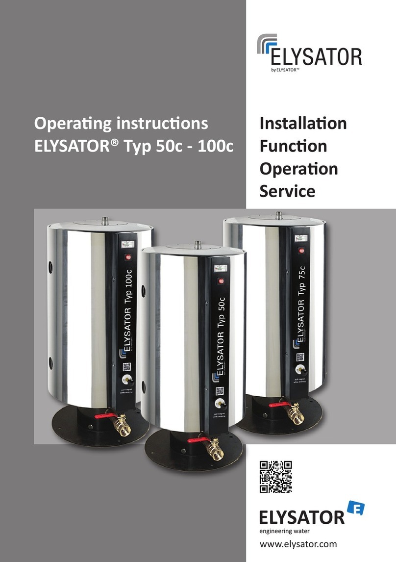
elysator 50c User manual
elysator
elysator PUROTAP expert Parts list manual

elysator
elysator PUROTAP 1000 Parts list manual

elysator
elysator PUROTAP profi 1 Series Parts list manual
elysator
elysator PUROTAP easy Installation and user guide

elysator
elysator PUROTAP profi 1 Series User manual

elysator
elysator PUROTAP profi Parts list manual
elysator
elysator PUROTAP micro User manual

elysator
elysator PUROTAP easy II User manual
elysator
elysator PUROTAP expert Owner's manual