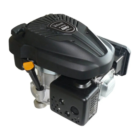
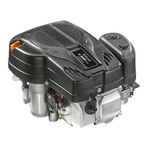
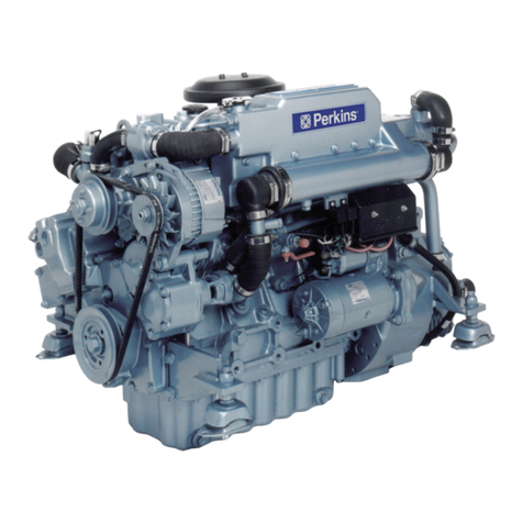
EMAK K 700 H Instruction manual

WORKSHOP MANUAL
Engine: K 700 H –K 800 H (183 cc)

Workshop manual
2
SAFETY PRECAUTIONS
Thoroughly read this MANUAL before operating and servicing the generator set. Safe operation and
top performance can only be attained when equipment is operated and maintained properly. The
following symbols, found throughout this manual, alert you to potentially dangerous conditions to
operators, service personnel and equipment.
This symbol alerts you to an immediate hazard that will result in severe personal injury
or death.
This symbol alerts you to a hazard or unsafe practice that can result in severe personal
injury or death.
This symbol alerts you to a hazard or unsafe practice that can result in personal injury
or damage to property.
Fuel, exhaust, and moving parts present hazards against which precautions must be taken to prevent severe
personal injury or death.
Be Careful when Fueling
As gasoline is flammable, fueling the engine must be performed in a well-ventilated outdoor place after the
engine is stopped.
No smoking is allowed during fueling, keep flames and sparks away.
Never start the engine before the place with spilled gasoline has not dried.
Hot Exhaust
Muffler temperature is very high during engine’s running, and even remains hot after engine has been
stopped for a while. Be careful not to touch a hot muffler. Stop the engine indoors, then cool the engine
indoors, and start maintenance after cooling.
In order to avoid fire, the engine shall be kept at least 1 m from any wall or any other equipment when it is
working. Flammables shall all the more be kept far away from the engine.
Carbon Monoxide
The exhaust contains poisonous carbon monoxide. Avoid inhale the exhaust.
Never run the engine indoors.
Never run the engine in a closed garage or any other closed space.
General Precautions
Thoroughly read this MANUAL, get familiar with all the operating mechanisms and the correct methods for
using and maintaining the engine, and master the operation method for stopping the engine and quickly
declutching.
Don’t operate the engine when you are tired, sick or have drunk any alcoholic beverage, or you may be
seriously injured.
Children, persons who haven’t read this Manual, or haven’t be trained are prohibited from using the engine.
Never repair the machine at will without mastering the method for repairing the engine.
Don’t modify the machine or change its structure at will; once the machine loses balance, it is very likely to
cause damage or injury accidents.

Workshop manual
3
1. Parameters................................................................................................................................ 4
1.1 Engine Structure ........................................................................................................................... 4
1.2 Product Technical Parameters ...................................................................................................... 6
1.3 Drawings of Mounting Dimensions................................................................................................ 7
1.4 Drawings of PTO Dimensions ....................................................................................................... 8
1.5 Diagram of Electrical Wiring........................................................................................................ 10
2. Service information................................................................................................................ 12
2.1 Precautions for Maintenance....................................................................................................... 12
2.2 Serial number location................................................................................................................. 13
2.3 Maintenance standards............................................................................................................... 14
2.4 Fastener Torque Specification..................................................................................................... 15
3. Maintenance ........................................................................................................................... 16
3.1 Maintenance schedule ................................................................................................................ 16
3.2 Engine oil.................................................................................................................................... 17
3.3 Air cleaner................................................................................................................................... 18
3.4 Muffler......................................................................................................................................... 19
3.5 Spark plug................................................................................................................................... 19
3.6 Valve clearance........................................................................................................................... 20
3.7 Carburetor................................................................................................................................... 20
3.8 Oil alert system inspection........................................................................................................... 20
3.9 Governor..................................................................................................................................... 21
3.10 Fuel filter..................................................................................................................................... 21
4. Troubleshooting..................................................................................................................... 22
4.1 Hard Starting............................................................................................................................... 22
4.2 Low Power .................................................................................................................................. 23
4.3 Speed Unstable........................................................................................................................... 24
4.4 Exhaust Colour Abnormal............................................................................................................ 24
4.5 Engine Liable to Stall................................................................................................................... 25
4.6 Engine Liable to Stall................................................................................................................... 25
4.7 Engine overheating ..................................................................................................................... 26
4.8 Engine’s Abnormal Sound........................................................................................................... 27
4.9 Electric Starting System Failure................................................................................................... 28
4.10 Cylinder Compression Check...................................................................................................... 29
4.11 Spark Test................................................................................................................................... 29
5. Disassembly and service....................................................................................................... 30
5.1 Precautions for Disassembly....................................................................................................... 30
5.1.1. Disassembly .................................................................................................................... 30
5.1.2. Reassembly..................................................................................................................... 30
5.2 Disassembly and Service of Engine............................................................................................ 31
5.2.1. Fuel tank.......................................................................................................................... 31
5.2.2. Air cleaner, Muffler........................................................................................................... 32
5.2.3. Air cleaner, Muffler........................................................................................................... 33
5.2.4. Governor System............................................................................................................. 36
5.2.5. Recoil starter.................................................................................................................... 37
5.2.6. Flywheel, ignition coil....................................................................................................... 40
5.2.7. Cylinder head, Valves...................................................................................................... 42
5.2.8. Crankcase, camshaft, piston............................................................................................ 48
5.2.9. Governor.......................................................................................................................... 55

Workshop manual
4
1
1
1. Parameters
1.1 Engine Structure
Fuel cock: a switch in the fuel line to control the fuel flow in the fuel line.
Recoil starter: serves to start the engine
Choke lever: closes the choke before engine’s cold starting, and the carburetor will deliver a very rich
mixture to let the engine be easily startable. When the engine has warmed up, the choke
lever shall be fully opened.
Engine switch: before starting the engine, the switch shall be put in the ON position; if you put the switch in
the OFF position the engine will be shut down
Throttle lever: serves to adjust the engine speed, so as to obtain the power and speed you want.
THROTTLE LEVER
CHOKE LEVER
FUEL COCK
STARTER GRIP
RECOIL STARTER
ENGINE SWITCH
OIL DRAIN PLUG

Workshop manual
5
Air cleaner: protects the engine through removing dust and other impurities in the air.
Spark plug: delivers the high voltage of the ignition coil into the engine’s combustion chamber, and
produces sparks by electric discharge between electrodes, to ignite the fuel-air mixture.
Muffler: prevents the engine noise from traveling, so as to lower noise of the exhaust system.
Fuel tank cap: when loosened, fuel can be added into the fuel tank; when tightened, fuel can be sealed in
the fuel tank.
Fuel tank: stores the fuel and delivers fuel to the carburetor.
Oil drain plug: when loosened, all engine oil in the engine can be drained off so that engine oil can be
change.
FUEL FILLER CAP
FUEL TANK
AIR CLEANER
OIL DRAIN PLUG
SPARK PLUG
MUFFLER

Workshop manual
6
1.2 Product Technical Parameters
Model
K700H –K800H
Type
Single cylinder, 4-Stroke, Forced Air Cooling, OHV 25°
Displacement (cc)
183 cc
Cylinder bore × Stroke (mm)
65×55
Net power (KW / 3600 rpm)
4
Net torque (Nm / rpm)
10.8 / 2500
Idle speed (rpm)
1800 ±150
Compression ratio
8.5 : 1
Output rotation
Counter clockwise close (from P.T.O. side)
Noise (≤7m)
≤ 70 dB(A)
Igniting mode
Transistorized magneto Ignition
Starting mode
Recoil / Electric
Carburetor
Butterfly
Lubrication system
Splash lubrication
Governor system
Centrifugal mass type
Air cleaner
Semi-dry, dual element
Oil capacity
0.6 L
Fuel tank capacity
3.0 L
Net weight (kg)
16/18
Dimensions (L×W×H) (mm)
381 × 325 × 327

Workshop manual
7
1.3 Drawings of Mounting Dimensions

Workshop manual
8
1.4 Drawings of PTO Dimensions
Type A Type C
Type R Type D

Workshop manual
9
Type E Type S
Type U Type A22

Workshop manual
10
1.5 Diagram of Electrical Wiring

Workshop manual
11
Engine Type with Oil Alert and Without Electric Starting

Workshop manual
12
2. Service information
2.1 Precautions for Maintenance
1. Parts, oil and grease must be genuine Efco and
Oleo-mac products or products designated by
Efco and Oleo-mac. Parts not meeting Efco and
Oleo-mac’s design specifications may damage
the device or engine.
2. Work to be done with special tools must be done
with such tools and corresponding devices.
3. Gaskets, washers, O-rings and oil seals must be
replaced after disassembly.
4. When screwing bolts, nuts or screws, tighten
from the ones of larger diameters and on inner
side to the ones of smaller diameters and on the
outer side, and tighten in a crisscross pattern to
the specified torque diagonally.
5. Clean parts in cleaning solvent upon
disassembly. Lubricate any sliding surfaces
before reassembly.
6. After reassembly, check all parts for proper
installation and operation.
7. Don’t maintain unless the engine is stopped and
has cooled, otherwise, bun can happen when
engine is hot.
8. If you want to perform a test run of the engine in
the work area after maintenance, take care to
ensure adequate ventilation in the area, and
never smoke or light a fire near fuel, grease or
other inflammable materials.

Workshop manual
13
Follow the instructions represented by these symbols when maintaining:
: Used oil
: Used special tool
: Used grease
○×○ (○):Indicates flange bolt model, length and quantity.
P. :Indicates pages
2.2 Serial number location
The serial number is stamped on the crankcase, as shown on the following drawing when inquiring about
engine or ordering parts in order to get correct parts for the unit being serviced by Efco or Oleo-Mac.
ENGINE MODEL
SERIAL NUMBER

Workshop manual
14
2.3 Maintenance standards
Part
Item
Standard
Service limit
K700H –K800H
K700H –K800H
Engine
Compression pressure (kg/cm2) *
6.5 ~ 8.5
-
Cylinder
Cylinder bore
65
65.165
Piston
Skirt outside diameter
64.985
64.845
Piston-to-cylinder clearance
0.015 ~0.005
0.12
Piston pin bore inside diameter
17.002 ~17.008
17.12
Piston pin –to –piston pin bore clearance
0.002 ~0.014
0.06
Piston pin
Outside diameter
13.0
12.954
Piston ring
Side clearance (top/second)
0.015 ~0.045
0.15
End gap (top/second)
0.20 ~0.40
1.0
Width (top)
0.15 ~0.35
1.0
Width (second)
1.5
1.37
Width (oil ring)
2.5
2.37
Connecting rod
Small end inside diameter
13.005
13.07
Big end inside diameter
30.22
30.246
Big end oil diameter
0.04 ~0.063
0.12
Big end side clearance
0.1 ~0.7
1.1
Crankshaft
Crack pin outside diameter
30.16
30.1
Valve
Clearance(cold) (intake)
0.15 + 0.02
-
Clearance(cold) (exhaust)
0.20 + 0.02
-
Stem diameter (intake)
5.48
5.318
Stem diameter (exhaust)
5.44
5.275
Valve guide
Inside diameter (intake, exhaust)
5.50
5.572
Stem to guide clearance (intake)
0.02 ~0.044
0.10
Stem to guide clearance (exhaust)
0.06 ~0.087
0.12
Valve seat
Seat width
0.8
2.0
Valve spring
Free length
30.5
29.5
Cam shaft
Height (intake)
27.7
27.45
Height (exhaust)
27.75
27.50
Outside diameter (bearing)
13.984
13.916
Crankcase cover
Camshaft holder internal diameter
14.0
14.048
Spark plug
Gap
0.7 ~0.8
-
Igniter coils
Resistance (primary)
0.8 ~ 1.0 Ω
-
Resistance (secondary)
5.9 ~ 7.1 Ω
-
Gap to flywheel
0.4 ± 0.2 mm
-
Unspecified unit: mm
* Value at the speed 1400 rpm of the engine.

Workshop manual
15
2.4 Fastener Torque Specification
(1) Torque specification
Item
Thread specification
Torque range (Nm)
Connecting rod bolt
M7x1
13 ~ 15
Cylinder head bolt
M8×1.25
32 ~ 35
Flywheel mounting nut
M14×1.5
80 ~ 90
Crankcase cover bolt
M8×1.25
27 ~ 30
Oil drain bolt (in crankcase)
M10×1.25
20 ~ 25
Air cleaner mounting nut
M6×1
8 ~ 12
Pivot adjusting nut
M6×0.75
12 ~ 16
Pivot bolt
M8×1.25
28 ~ 32
Governor arm nut
M6×1.0
9 ~ 13
Starter motor fastening bolt
M6×1.25
8 ~ 12
Spark plug
27 ~ 30
(2) Standard Torques specification
Faster
Thread specification
Torque range (Nm)
Bolt, nut
5 mm bolt, nut
4 ~ 7
6 mm bolt, nut
8 ~ 12
8 mm bolt, nut
20 ~ 28
10 mm bolt, nut
35 ~ 40
12 mm bolt, nut
50 ~ 60

Workshop manual
16
3. Maintenance
3.1 Maintenance schedule
Maintenance schedule
Each
use
First
month
or 20
hours
Every 3
months
or 50
hours
Every 6
months
or 100
hours
Every
year or
300
hours
Engine oil
Check level
●
Replace
●
●
Air filter
Check
●
Clean
● (1)
Replace
●
Fuel strainer cup
Clean
●
Battery electrolyte level
Check
●
Spark plug
Clean
●
Replace
Valve clearance
Readjust
● (2)
Combustion chamber
Clean
Every 300 hours (2)
Fuel tank and strainer
Clean
Every 2 years (2)
Fuel tube
Replace
Every 2 years (2)
(1) Replace paper element only.
(2) Service more frequently when used in a dust area.

Workshop manual
17
3.2 Engine oil
Note
Oil is the major factor affecting performance and service
life. Don’t use oil containing additives and 2-stroke engine
oil, because they lack sufficient lubricating ability and will
shorten the gasoline engine’s service life.
Check the oil level with the engine stopped and on a flat
level surface.
Oil capacity: 0.60 L
In order to obtain the best performance of the engine, it is
recommended to use special engine oil certified to be OK for
Emak engines. SAE 10W-30 is the recommended oil. Other
viscosities shown in the chart may be used when the average
temperature in your area is within the recommended range.
Oil level check:
1) Remove the oil cap/dipstick and wipe it clean.
2) Insert the oil dipstick into oil filler neck but do not screw it
in, and check oil level.
3) Oil level is too low if there is no oil on the dipstick. Add
recommended oil to bring the oil level to the upper limit of
the dipstick.
4) Reinstall the cap/ dipstick securely.
Warning
Drain the oil while the engine is stopped yet warm to
ensure rapid and complete draining.
Used engine oil contains carcinogenic substances. If repeatedly left in contact with the skin
for prolonged periods, it may cause skin cancer. Wash your hands thoroughly with soap
and water as soon as possible after contact with used engine oil.
Please dispose of used motor oil and the oil containers in a manner that is friendly to the
environment. We suggest you put it in a sealed container and take it to your local recycling
center or service station for reclamation. Do not throw it in the trash, or pour it on the
ground.
Oil dipstick
Oil drain bolt
Ambient temperature
Upper limit
Lower limit

Workshop manual
18
3.3 Air cleaner
A dirty air filter will restrict fair flow to the carburetor, reducing engine performance. If the engine is
operated in dusty areas, clean the air cleaner more often than specified in the MAINTENANCE
SCHEDULE
Warning
Note
Oil batch air cleaner
1) Remove wing nut, air cleaner cover
and cap, and take out element.
2) Wash the element in a solution of
household detergent and warm
water, then rinse thoroughly, or
wash in non-flammable or high
flash point solvent. Allow the
element to dry thoroughly. Soak
the air filter element in clean
engine oil and squeeze out the
excess oil.
3) Rinse air cleaner cover and cap in
warm water with detergent and
allow them to dry thoroughly.
4) Empty the used oil from the air
cleaner case and wash out any
accumulated dirt with non-
flammable solvent, and dry the
case.
5) Fill the air cleaner case to the OIL LEVEL mark with the same oil that is recommended for the engine.
Oil capacity: 60 cc.
6) Reinstall the air cleaner parts and tighten the wing nut securely.
Washing filter element with gasoline or flammable solvents many cause fire or explosion, please
use soapy water or nonflammable solvent.
Operating the engine without an air filter element or with a damaged air filter will allow dirt to enter
the engine, causing rapid engine wear.
Wing nut
Air cleaner
cover
Element
Grid
Air
cleaner
case
OIL LEVEL

Workshop manual
19
3.4 Muffler
Long use of the muffler can cause carbon deposit, which will
severely affect the exhaust system; in order to let exhaust system
work more reliably, we normally need toremove the carbon deposit
from the muffler.
Use a hand hammer to gently knock the muffler, and blow it with
compressed air to remove the carbon deposit inside it.
If the muffler has water drops in it, and severeerosion, which cause
higher exhaust noise, replace it with a new one.
Never use wires to clean, or the acoustic absorbent will be scraped
off, and acoustic absorbing performance will be worse.
Never reuse the muffler gasket.
3.5 Spark plug
Recommended type: F7RTC or a spark plug of an equivalent
grade. Replacing the spark plug has the following positive effect:
ensuring continuous production of sparks, more reliable starting.
Caution
1. Remove the spark plug cap, and remove the dirt from around
the spark plug.
2. Remove the spark plug with a spark plug wrench.
3. Inspect the spark plug for excessively worn electrodes, chips or
cracks in theinsulator, orexcessive deposits. Replace the spark
plug if you have any doubts about its condition.
4. Measure the electrode gap with a gap gauge; the correct gap is
0.7 ~ 0.8 mm; if the gap need be adjusted, slightly knock (when
the gap is to big), or slightly pry the electrode with a slot type
screwdriver (when the gap is too small).
5. Use a spark plug wrench to tighten the spark plug enough to let
it press on the washer. If reinstalling a used spark plug, tighten
1/8 to 1/4 of a turn after the spark plug presses on the washer.
If installing a new spark plug, tighten 1/2 turn after the spark
plug presses on the washer.
Caution
6. Install the spark plug cap on the spark plug.
Spark plugs of a wrong model or incorrect heat range can
cause engine damage.
A loosely installed spark plug can become hot enough to
damage the engine. Over tightening a spark plug can
damage the threads in the engine.
0.7-0.8 mm
Side electrode
Wire brush
Spark plug
wrench

Workshop manual
20
3.6 Valve clearance
Valve clearance inspection and adjustment must be done with the
engine cold.
1. Remove the cylinder head cover, and set the piston at top dead
centre of the compression stroke (both valves will be fully
closed).
2. Measure the clearance between the rocker arm and the valve
stem with a feeler gauge.
Intake: 0.15 ± 0.02 mm
Exhaust: 0.20 ± 0.02 mm
3. To adjust valve clearance, hold the rocker arm pivot and loosen
the pivot lock nut.
4. Turn the rocker arm pivot to obtain the specified clearance.
5. Hold the rocker arm pivot and tighten the pivot lock nut.
6. Recheck the clearance and readjust if necessary.
7. Install the cylinder head cover.
3.7 Carburetor
Idle speed
1) Start the engine andallow it to warm up for about10 minutes.
2) Set the throttle lever in the position for lowest speed.
3) Use tools to adjust the throttle stop screw, to bring the idle
speed within the range of standard idle speed.
Standard idle speed: 1800 ± 150 rpm.
3.8 Oil alert system inspection
Oil alert system is specially designed to protect engine from
damage by insufficient oil in the crankcase. Before the oil level in
the crankcase can fall below a safe limit, the oil alert system will
automatically shut down the engine (the engine switch will
remain in the ON position). The oil alert system shuts down the
engine and the engine will not start. If this occurs, first check
engine oil level, then check for other faults.
1) With the engine running, disconnect the engine switch’s
yellow lead and ground it to the engine, the engine should
stop.
2) With the engine stopped, engine oil level within the specified
range and two leads of oil level switch not disconnected,
there should be continuity between the two leads.
3) Then check with engine oil drained off. There should be
continuity between leads of oil level switch.
Throttle stop screw
Oil alert unit
Oil level switch
Feeler gauge
Valve clearance
Rocker arm
Pivot lock
nut
Rocker arm pivot
Push rod
Valve stem
This manual suits for next models
1
Table of contents
Other EMAK Engine manuals
