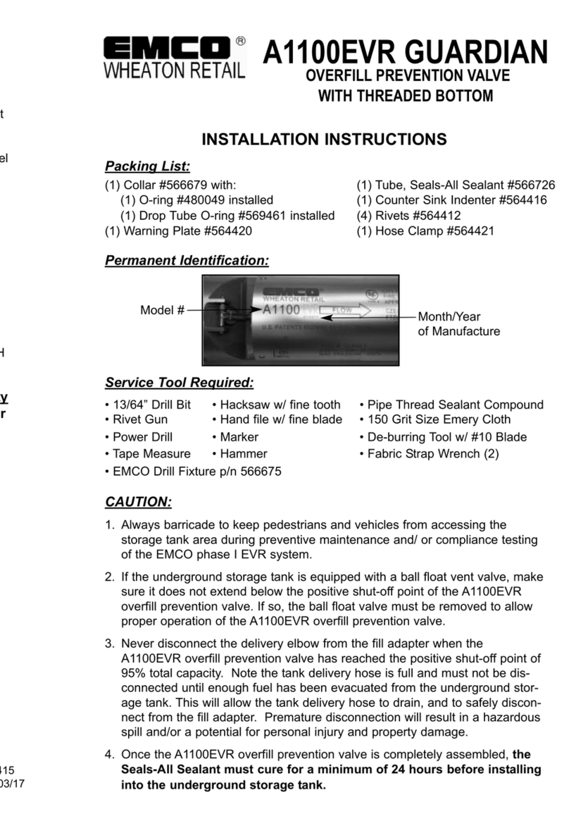
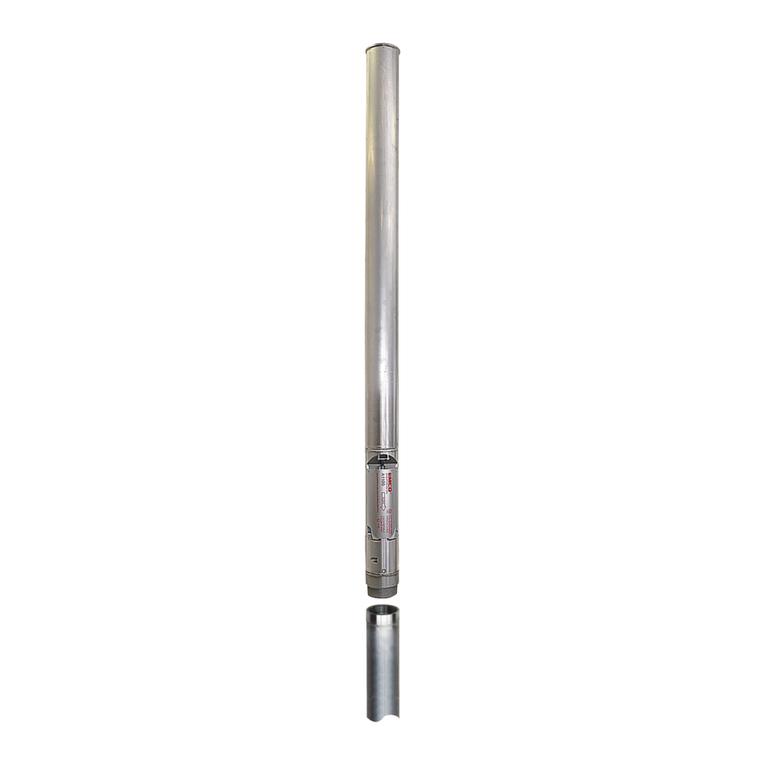
Emco A1100 Instruction manual

A1100 GUARDIAN
OVERFILL PREVENTION VALVE
(with 493192 Installation Kit)
Assembly and Installation Instructions
Important: Read these instructions completely and carefully before attempting to
install and operate this valve. Failure to do so may result in improper valve opera-
tion allowing for a potential storage tank overfill. An overfilled tank can create
extremely hazardous fuel spills which may result in personal injury and property
damage. For further information, please call our Customer Service Department at
(252) 243-0150.
Important: Veuillez lire ces instructions attentivement avant d'installer et d'exploiter
cette vanne. Ne pas le faire peut entraîner un fonctionnement incorrect de la vanne
permettant un potentiel débordement de la citerne de stockage. Un réservoir trop
plein peut créer des déversements de carburant extrêmement dangereuses qui peu-
vent entraîner des blessures et des dommages matériels. Pour plus d'informations,
s'il vous plaît communiquer avec notre service à la clientèle au (252) 243-0150.
Note: All information, illustrations and specifications in this manual are based on the lat-
est product information available. We reserve the right to make changes at any time with-
out notice.
Assembly 2-7
Tools 2
Packing List 2
Procedure 2-6
Installation 7
General Maintenance 8
Warranty 8
p/n 564417
Rev. P, 07/18
MAINTENANCE
The A1100 Guardian is maintenance free. Periodic inspection of drop tube
wear due to corrosion is suggested.
Please leave these instructions with the owner/operator of the service station for
future reference.
WARRANTY
Emco Wheaton Retail Corporation service station products are warranted to be
free from defects in material and workmanship under normal use and service for
a period of twelve (12) months from the date of manufacture.
The warranty set forth herein shall be the exclusive warranty made by Emco
Wheaton Retail Corporation and in lieu of all other warranties, expressed or
implied, (whether written or oral), including but not limited to any implied warran-
ty of merchantability or fitness for any particular purpose.
Emco Wheaton Retail Corporation’s liability under this warranty is limited to, at
Emco Wheaton Retail Corporation’s option, the repair or replacement of that
part which proves to be defective within twelve (12) months of date of manufac-
ture. Emco Wheaton Retail Corporation is not responsible for claims for dam-
age due to improper installation or maintenance, corrosive fluids, or use of a
product for a purpose other than that for which it was specifically designed.
Emco Wheaton Retail Corporation shall have no liability or be required to fulfill
any obligation under this warranty unless the original purchaser returns the
claimed defective item to Emco Wheaton Retail Corporation for inspection to
determine whether the claimed defect is covered by this warranty.
Under no circumstances shall Emco Wheaton Retail Corporation be liable for
any consequential, special or contingent damages or expenses or any other
charges beyond the invoice value of the defective items. The remedies set forth
herein shall be the exclusive remedies available to the user and are in lieu of all
other remedies except for the remedies described below.
If an Emco Wheaton Retail Corporation product fails within the warranty period,
call the Customer Service Department at (800) 234-4394. Describe the problem
and provide the product date stamp information to the customer service repre-
sentative. The customer service representative will provide a product complaint
number, if applicable. Ship the defective equipment PREPAID, to Emco
Wheaton Retail Corporation for repair or replacement.
Emco Wheaton Retail Corporation products should be used in compliance with
applicable federal, state and local laws and regulations. Product selection
should be based on physical specifications and limitations and compatibility with
the environment and material to be handled. EMCO WHEATON RETAIL COR-
PORATION MAKES NO WARRANTY OF FITNESS FOR A PARTICULAR USE.
All illustrations and specifications in this catalog are based on the latest product
information available at the time of publication. Emco Wheaton Retail
Corporation reserves the right to make changes at any time in prices, materials,
specifications and models and to discontinue models without notice or obliga-
tion.
CAUTION: Never disconnect the drop elbow from the tight-fill adapter when the A1100
has reached the positive shut-off level. At this point, the tank truck hose is still full and
must not be disconnected until enough fuel has been removed from the underground stor-
age tank to drain the hose. Premature disconnection will result in a hazardous spill and a
potential for personal injury and property damage.
ATTENTION: Ne jamais déconnecter le coude de baisse de l'adaptateur permet le rem-
plissage étanche lorsque le A1100 a atteint le niveau d'arrêt positive. A ce point, le tuyau
de camion-citerne est encore pleine et ne doit pas être débranché jusqu'à ce que suff-
isamment de carburant a été éliminée du réservoir de stockage souterrain pour vidanger
le tuyau. Déconnexion prématurée entraîne un déversement dangereux et un risque de
blessures et de dommages matériels.
© 2018 Emco Wheaton Retail Corporation

ASSEMBLY
Tools Needed
1. 13/64" drill bit 6. hammer
2. hand drill 7. fine half round file
3. tape measure 8. heavy duty pop rivet gun
4. fine tooth hacksaw (24-36 teeth per inch)
Packing List (included with A1100-010)
(1) valve assembly #A1100 (8) pop rivets #564412
(1) hose clamp #564421 (1) o-ring #480049
(1) warning plate #564420 (1) counter sink indenter #564416
(1) drop tube O-ring #561683 (1) Seal-All sealant #566726
(1) 572719 drill fixture
NOTICE:If this valve is to be used with coaxial Stage I drop tube assemblies, you must
order the appropriate special kit for proper assembly:
Standard coaxial (A0070 style) kit #493195
Self sealing coaxial (A0088 style) kit #493197
The A1100 Guardian can only be installed after the containment manhole has
been installed. Existing drop tube may be used only if:
1. Tube is in good condition without holes, cracks, or bends.
2. I.D. of tube will fit over the valve body diameter.
Step 1:If already in place, remove the existing 4” cap, adapter and drop tube
assembly.
Step 2: Find measurement A which is the distance from the top of the tank to
the top of the 4” riser pipe as shown in Figure 1.
If the tank has a manway, make sure to include the height of the manway when
finding measurement A as shown in Figure 2, A = J+H. Consult your tank dia-
gram to determine the proper H dimension. If this dimension cannot be found,
use 6” as the H dimension (typical manway height is 5”-7”).
WARNING: Do not use electrical devices near gasoline vapors, as it could result in fire
or explosion.
AVERTISSEMENT: Ne pas utiliser d'appareils électriques à proximité des vapeurs
d'essence, car il pourrait provoquer un incendie ou une explosion.
WARNING: If the underground storage tank is equipped with a ball float vent
valve, make sure it is not extended below the positive shut-off point of the A1100, or
remove the float vent valve.
ATTENTION: Si le réservoir de stockage souterrain est équipé d'un flotteur évent de balle
vanne, assurezvous qu'il n'est pas prolongée en dessous du point d'arrêt positive de la
A1100, ou supprimer la vanne flotteur de ventilation.
TOP TUBE INSTALLATION PROCEDURE
2
Step 21: Turn completed assembly upside down and shake vertically to
remove any metal chips left from the drilling process.
The system is now in place and ready for operation.
7
INSTALLATION OF COMPLETED ASSEMBLY INTO THE TANK
Step 22: Install the O-ring (p/n
561683, supplied) on the top flange.
Step 23: Position the completed
assembly vertically over the riser
pipe with the square cut down.
Carefully lower the completed drop
tube/valve assembly into the riser
pipe.
Step 24: Use the hose clamp
to clamp the warning plate (p/n 564420,
supplied) onto the riser below the threads.
Make sure label is facing up.
Step 25: Reinstall the adapter onto the
riser and torque with an adapter wrench.
Replace the tightfill cap.

Step 17: Subtract 6” from measurement D to obtain the correct total assembly
length E. Measure length E (D - 6”= E) on the assembly from the flanged end.
Mark tube to length E.
Step 18: Secure the hose clamp to the tube.
Step 19: Square cut the the lower tube to
length E.
Optional: 45 degree cut - The shortest
point should start at length E to maintain
the 6” maximum
clearance
requirement at
bottom of tank.
6
Step 15: Using the indent tool,
countersink one hole and install a
rivet. Apply sealant over the rivet.
Repeat with remaining three holes.
Step 16: Measure from top of riser
pipe to the bottom inside of the
tank, measurement D, Figure 1.
Figure 1
Figure 2
Riser Pipe Installed Inside Manway 3
Riser Pipe With Spill Containment Manhole
E
BOTTOM TUBE INSTALLATION PROCEDURE
Step 14: Lubricate bottom of
A1100 valve with Seal-All and
install bottom tube, being careful to
align holes.
Step 13: Slide the 572719 Drill
Fixture on drop tube. Drill the four
holes using the 13/64” drill bit.
Remove drill fixture. File cutting
burrs from end of tube.

Step 4: To determine the top tube cut length, C: Add A and B; subtract 2”.
A + B - 2 = C
Step 5: Place a tape measure at one end of the drop tube and mark length C.
Note: If you are using an unflanged tube, you will require part #566679 collar kit.
4
Step 9: Slide the drill fixture (p/n
572719, supplied) on the drop tube.
Drill the four holes using the 13/64”
drill bit. Remove drill fixture and set
aside.
Step 8: Remove clamp. File away
cutting burrs to prevent damage to
the O-ring when attaching to the
valve.
5
Step 10: Lubricate the O-ring (p/n
480049, supplied) with the Seal-All
and insert into the top groove of
the A1100 valve. Lubricate the top
1” of the outside circumference of
the valve with Seal-All.
Step 11: Insert the A1100 valve
into the top tube. Align the holes.
Step 12: Using the indent tool #564416, countersink one hole. Secure with a
pop rivet. Apply sealant over the rivet. Repeat this process with the remaining
three holes.
Step 3: Find measurement B from the chart below. It is the distance from the
maximum fluid height allowed to the inside top of the tank. Calculations are based
on cylindrical tanks with flat ends. For exact dimensions, consult the tank gauge
chart provided with your tank. Use the actual capacity of the tank for calculations.
NFPA30 Guidelines limit tank fill to 95%.
95% Shut-off
Tank Diameter B Dimension
Feet Meters Inches MM
6.5’ 1.98 7.5" 190
7.0’ 2.13 8.0" 203
7.6’ 2.29 9.0" 229
8.0’ 2.44 9.5" 241
8.2’ 2.50 9.5" 241
8.5’ 2.59 10.0" 254
9.0’ 2.74 10.5" 267
9.5’ 2.90 11.0" 279
10.0’ 3.05 11.5" 292
12.0’ 3.66 14.0" 336
The A1100 Overfill Prevention Valve is not recommended for tanks under 6.5’ in
diameter.
Step 7: Cut tube to proper length
using a fine tooth hacksaw. The
hose clamp acts as a guide.
IMPORTANT: Do not use a power
saw or tubing cutter to cut the
tube.
Step 6: Secure the hose clamp
(p/n 564421, supplied) at cut mark
C from Step 5 as shown.

Step 17: Subtract 6” from measurement D to obtain the correct total assembly
length E. Measure length E (D - 6”= E) on the assembly from the flanged end.
Mark tube to length E.
Step 18: Secure the hose clamp to the tube.
Step 19: Square cut the the lower tube to
length E.
Optional: 45 degree cut - The shortest
point should start at length E to maintain
the 6” maximum
clearance
requirement at
bottom of tank.
6
Step 15: Using the indent tool,
countersink one hole and install a
rivet. Apply sealant over the rivet.
Repeat with remaining three holes.
Step 16: Measure from top of riser
pipe to the bottom inside of the
tank, measurement D, Figure 1.
Figure 1
Figure 2
Riser Pipe Installed Inside Manway 3
Riser Pipe With Spill Containment Manhole
E
BOTTOM TUBE INSTALLATION PROCEDURE
Step 14: Lubricate bottom of
A1100 valve with Seal-All and
install bottom tube, being careful to
align holes.
Step 13: Slide the 572719 Drill
Fixture on drop tube. Drill the four
holes using the 13/64” drill bit.
Remove drill fixture. File cutting
burrs from end of tube.

ASSEMBLY
Tools Needed
1. 13/64" drill bit 6. hammer
2. hand drill 7. fine half round file
3. tape measure 8. heavy duty pop rivet gun
4. fine tooth hacksaw (24-36 teeth per inch)
Packing List (included with A1100-010)
(1) valve assembly #A1100 (8) pop rivets #564412
(1) hose clamp #564421 (1) o-ring #480049
(1) warning plate #564420 (1) counter sink indenter #564416
(1) drop tube O-ring #561683 (1) Seal-All sealant #566726
(1) 572719 drill fixture
NOTICE:If this valve is to be used with coaxial Stage I drop tube assemblies, you must
order the appropriate special kit for proper assembly:
Standard coaxial (A0070 style) kit #493195
Self sealing coaxial (A0088 style) kit #493197
The A1100 Guardian can only be installed after the containment manhole has
been installed. Existing drop tube may be used only if:
1. Tube is in good condition without holes, cracks, or bends.
2. I.D. of tube will fit over the valve body diameter.
Step 1:If already in place, remove the existing 4” cap, adapter and drop tube
assembly.
Step 2: Find measurement A which is the distance from the top of the tank to
the top of the 4” riser pipe as shown in Figure 1.
If the tank has a manway, make sure to include the height of the manway when
finding measurement A as shown in Figure 2, A = J+H. Consult your tank dia-
gram to determine the proper H dimension. If this dimension cannot be found,
use 6” as the H dimension (typical manway height is 5”-7”).
WARNING: Do not use electrical devices near gasoline vapors, as it could result in fire
or explosion.
AVERTISSEMENT: Ne pas utiliser d'appareils électriques à proximité des vapeurs
d'essence, car il pourrait provoquer un incendie ou une explosion.
WARNING: If the underground storage tank is equipped with a ball float vent
valve, make sure it is not extended below the positive shut-off point of the A1100, or
remove the float vent valve.
ATTENTION: Si le réservoir de stockage souterrain est équipé d'un flotteur évent de balle
vanne, assurezvous qu'il n'est pas prolongée en dessous du point d'arrêt positive de la
A1100, ou supprimer la vanne flotteur de ventilation.
TOP TUBE INSTALLATION PROCEDURE
2
Step 21: Turn completed assembly upside down and shake vertically to
remove any metal chips left from the drilling process.
The system is now in place and ready for operation.
7
INSTALLATION OF COMPLETED ASSEMBLY INTO THE TANK
Step 22: Install the O-ring (p/n
561683, supplied) on the top flange.
Step 23: Position the completed
assembly vertically over the riser
pipe with the square cut down.
Carefully lower the completed drop
tube/valve assembly into the riser
pipe.
Step 24: Use the hose clamp
to clamp the warning plate (p/n 564420,
supplied) onto the riser below the threads.
Make sure label is facing up.
Step 25: Reinstall the adapter onto the
riser and torque with an adapter wrench.
Replace the tightfill cap.

A1100 GUARDIAN
OVERFILL PREVENTION VALVE
(with 493192 Installation Kit)
Assembly and Installation Instructions
Important: Read these instructions completely and carefully before attempting to
install and operate this valve. Failure to do so may result in improper valve opera-
tion allowing for a potential storage tank overfill. An overfilled tank can create
extremely hazardous fuel spills which may result in personal injury and property
damage. For further information, please call our Customer Service Department at
(252) 243-0150.
Important: Veuillez lire ces instructions attentivement avant d'installer et d'exploiter
cette vanne. Ne pas le faire peut entraîner un fonctionnement incorrect de la vanne
permettant un potentiel débordement de la citerne de stockage. Un réservoir trop
plein peut créer des déversements de carburant extrêmement dangereuses qui peu-
vent entraîner des blessures et des dommages matériels. Pour plus d'informations,
s'il vous plaît communiquer avec notre service à la clientèle au (252) 243-0150.
Note: All information, illustrations and specifications in this manual are based on the lat-
est product information available. We reserve the right to make changes at any time with-
out notice.
Assembly 2-7
Tools 2
Packing List 2
Procedure 2-6
Installation 7
General Maintenance 8
Warranty 8
p/n 564417
Rev. P, 07/18
MAINTENANCE
The A1100 Guardian is maintenance free. Periodic inspection of drop tube
wear due to corrosion is suggested.
Please leave these instructions with the owner/operator of the service station for
future reference.
WARRANTY
Emco Wheaton Retail Corporation service station products are warranted to be
free from defects in material and workmanship under normal use and service for
a period of twelve (12) months from the date of manufacture.
The warranty set forth herein shall be the exclusive warranty made by Emco
Wheaton Retail Corporation and in lieu of all other warranties, expressed or
implied, (whether written or oral), including but not limited to any implied warran-
ty of merchantability or fitness for any particular purpose.
Emco Wheaton Retail Corporation’s liability under this warranty is limited to, at
Emco Wheaton Retail Corporation’s option, the repair or replacement of that
part which proves to be defective within twelve (12) months of date of manufac-
ture. Emco Wheaton Retail Corporation is not responsible for claims for dam-
age due to improper installation or maintenance, corrosive fluids, or use of a
product for a purpose other than that for which it was specifically designed.
Emco Wheaton Retail Corporation shall have no liability or be required to fulfill
any obligation under this warranty unless the original purchaser returns the
claimed defective item to Emco Wheaton Retail Corporation for inspection to
determine whether the claimed defect is covered by this warranty.
Under no circumstances shall Emco Wheaton Retail Corporation be liable for
any consequential, special or contingent damages or expenses or any other
charges beyond the invoice value of the defective items. The remedies set forth
herein shall be the exclusive remedies available to the user and are in lieu of all
other remedies except for the remedies described below.
If an Emco Wheaton Retail Corporation product fails within the warranty period,
call the Customer Service Department at (800) 234-4394. Describe the problem
and provide the product date stamp information to the customer service repre-
sentative. The customer service representative will provide a product complaint
number, if applicable. Ship the defective equipment PREPAID, to Emco
Wheaton Retail Corporation for repair or replacement.
Emco Wheaton Retail Corporation products should be used in compliance with
applicable federal, state and local laws and regulations. Product selection
should be based on physical specifications and limitations and compatibility with
the environment and material to be handled. EMCO WHEATON RETAIL COR-
PORATION MAKES NO WARRANTY OF FITNESS FOR A PARTICULAR USE.
All illustrations and specifications in this catalog are based on the latest product
information available at the time of publication. Emco Wheaton Retail
Corporation reserves the right to make changes at any time in prices, materials,
specifications and models and to discontinue models without notice or obliga-
tion.
CAUTION: Never disconnect the drop elbow from the tight-fill adapter when the A1100
has reached the positive shut-off level. At this point, the tank truck hose is still full and
must not be disconnected until enough fuel has been removed from the underground stor-
age tank to drain the hose. Premature disconnection will result in a hazardous spill and a
potential for personal injury and property damage.
ATTENTION: Ne jamais déconnecter le coude de baisse de l'adaptateur permet le rem-
plissage étanche lorsque le A1100 a atteint le niveau d'arrêt positive. A ce point, le tuyau
de camion-citerne est encore pleine et ne doit pas être débranché jusqu'à ce que suff-
isamment de carburant a été éliminée du réservoir de stockage souterrain pour vidanger
le tuyau. Déconnexion prématurée entraîne un déversement dangereux et un risque de
blessures et de dommages matériels.
© 2018 Emco Wheaton Retail Corporation
Table of contents
Other Emco Control Unit manuals
