Texas Instruments 2000 series User manual
Other Texas Instruments Control Unit manuals
Texas Instruments
Texas Instruments CDCE 9 Series User manual
Texas Instruments
Texas Instruments bq2023EVM-001 User manual
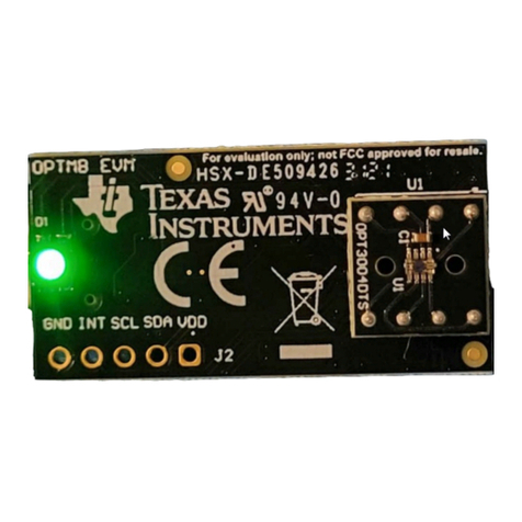
Texas Instruments
Texas Instruments OPT3004DTSEVM User manual
Texas Instruments
Texas Instruments UCC28740EVM-525 User manual
Texas Instruments
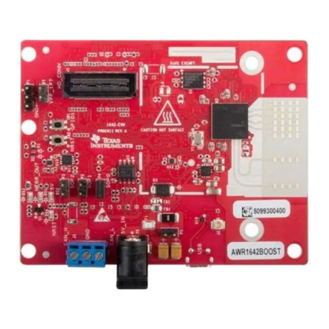
Texas Instruments AWR1642 User manual
Texas Instruments
Texas Instruments LM74700DDFEVM User manual
Texas Instruments
Texas Instruments BIOSUSB User manual
Texas Instruments
Texas Instruments 990 User manual
Texas Instruments
Texas Instruments TPS61310EVM-638 User manual
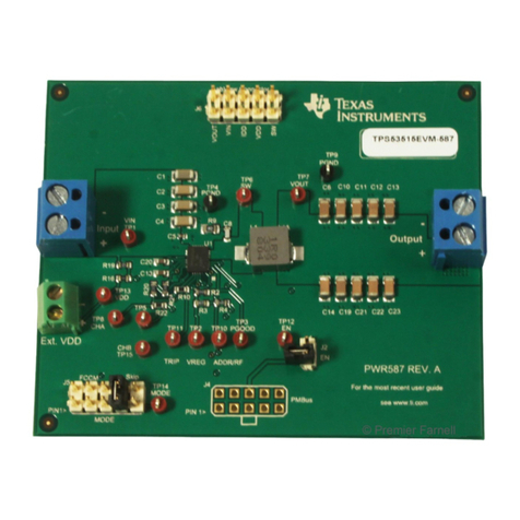
Texas Instruments
Texas Instruments TPS53515 User manual
Texas Instruments
Texas Instruments TPSM84424EVM User manual
Texas Instruments
Texas Instruments TPS1HA08x User manual
Texas Instruments
Texas Instruments DRV2605LEVM-MD User manual
Texas Instruments
Texas Instruments UCC27423-Q1 User manual
Texas Instruments
Texas Instruments TLV320DAC26EVM User manual
Texas Instruments
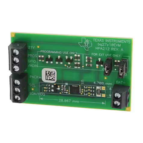
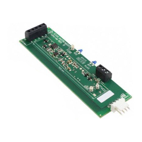
Texas Instruments bq20z70EVM-001 User manual
Texas Instruments
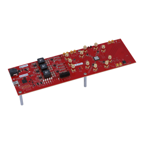
Texas Instruments ADC12DJ5200RF User manual
Texas Instruments
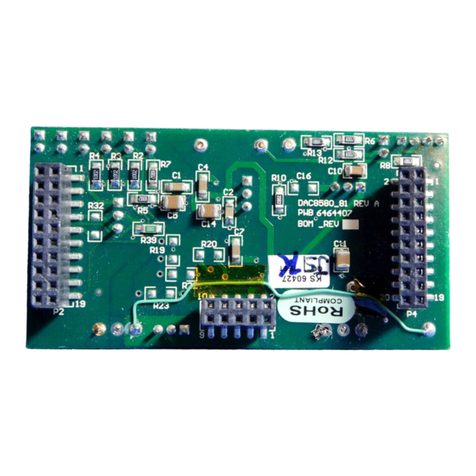
Texas Instruments DAC8580 User manual
Texas Instruments
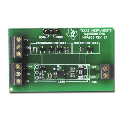
Texas Instruments bq26500EVM User manual
Texas Instruments
Texas Instruments DRV591 User manual
Popular Control Unit manuals by other brands

Festo
Festo Compact Performance CP-FB6-E Brief description

Elo TouchSystems
Elo TouchSystems DMS-SA19P-EXTME Quick installation guide

JS Automation
JS Automation MPC3034A user manual

JAUDT
JAUDT SW GII 6406 Series Translation of the original operating instructions

Spektrum
Spektrum Air Module System manual

BOC Edwards
BOC Edwards Q Series instruction manual

KHADAS
KHADAS BT Magic quick start

Etherma
Etherma eNEXHO-IL Assembly and operating instructions

PMFoundations
PMFoundations Attenuverter Assembly guide

GEA
GEA VARIVENT Operating instruction

Walther Systemtechnik
Walther Systemtechnik VMS-05 Assembly instructions

Altronix
Altronix LINQ8PD Installation and programming manual
