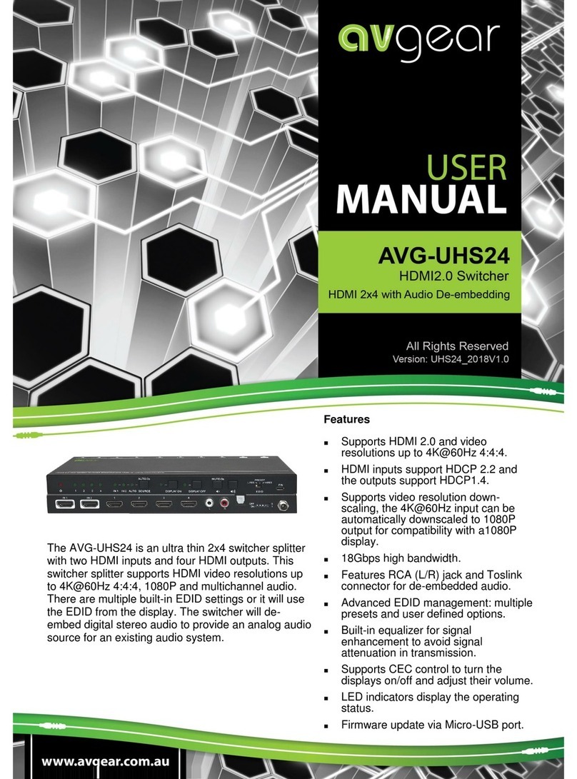
AVGear AVG-UHS41 DA User manual

AVG-UHS41 DA
Features
▪Switches any of the four HDMI inputs
to one HDMI output.
▪Supports video resolutions up to
4Kx2K@60Hz 4:4:4 HDR.
▪18Gbps high bandwidth.
▪Fully compliant with the HDMI 2.0
and HDCP2.2 specifications.
▪Supports audio return channel
(ARC).
▪Advanced EDID management:
multiple presets and user defineable
allowed.
▪Controllable via RS232 and IR.
▪Supports CEC.
▪Provides seven LEDs to indicate the
current operating status and to assist
troubleshooting and installation.
▪Firmware upgrade via Micro-USB
port.
The AVG-UHS41 DA is an ultrathin auto switcher with
four HDMI inputs and one HDMI output. This switcher
supports HDMI video resolutions up to 4Kx2K@60Hz
4:4:4 HDR and multichannel audio. There are multiple
built-in EDID settings or it will use the EDID from the
display. The switcher will de-embed digital stereo
audio to provide an analog audio source for an
existing audio system. The switcher also supports
audio return channel (ARC) for transmitting audio
back to the HDMI input and audio output ports from
the connected display.

AVG-UHS41 DA
PLEASE READ THIS PRODUCT MANUAL CAREFULLY
BEFORE USING THIS PRODUCT.
This manual is only for operational instruction only,
and is not to be used in a maintenance capacity. The
functions described in this version are current as of
May 2018. Any changes of functions and operational
parameters will be updated in future manual versions.
Please refer to your dealer for the latest product
details.
Version 1.0 24/5/18

AVG-UHS41 DA
SAFETY OPERATION GUIDE
In order to guarantee the reliable operation of the equipment and safety of the
user, please abide by the following procedures in installation, use and
maintenance:
1. The system must be earthed properly. Please do not use two blade plugs
and ensure the AC power supply ranges from 100v to 240v and from 50Hz
to 60Hz.
2. Do not install the switcher in an environment where it will be exposed to
extreme hot or cold temperatures.
3. This unit will generate heat during operation, please ensure that you allow
adequate ventilation to ensure reliable operation.
4. Please disconnect the unit from mains power if it will be left unused for a
long time.
5. Please DO NOT try to open the casing of the equipment, DO NOT attempt to
repair the unit. Opening the unit will void the warranty. There are high
voltage components in the unit and attempting to repair the unit could result
in serious injury.
6. Do not allow the unit to come into contact with any liquid as that could result
in personal injury and product failure.

AVG-UHS41 DA
TABLE OF CONTENTS
Introduction .............................................................................................................1
Introduction to the AVG-UHS41 DA .............................................................1.1
Features ......................................................................................................1.2
What’s in the Box .........................................................................................1.3
Panel Description of the AVG-UHS41 DA...............................................................2
Front Panel ..................................................................................................2.1
Rear Panel ...................................................................................................2.2
System Connection .................................................................................................3
Usage Precautions ......................................................................................3.1
System Diagram...........................................................................................3.2
System Application.......................................................................................3.3
System Control ........................................................................................................4
Manual Switching Mode ...............................................................................4.1
Auto Switching Mode....................................................................................4.2
IR Control ....................................................................................................4.3
RS232 Control .............................................................................................4.4
EDID Management ...................................................................................................5
Predefined EDID Setting ..............................................................................5.1
User Defined EDID Setting...........................................................................5.2
ARC Mode ................................................................................................................6
Firmware Upgrade ...................................................................................................7
Specifications ..........................................................................................................8
Panel Drawing ..........................................................................................................9
Troubleshooting & Maintenance...........................................................................10

AVG-UHS41 DA
1. Introduction
1.1 Introduction to the AVG-UHS41 DA
The AVG-UHS41 DA is an ultrathin auto switcher with four HDMI inputs and one
HDMI output. This switcher supports HDMI video resolutions up to 4Kx2K@60Hz
4:4:4 HDR and multichannel audio. There are multiple built-in EDID settings or it will
use the EDID from the display. The switcher will de-embed digital stereo audio to
provide an analog audio source for an existing audio system.
The switcher also supports audio return channel (ARC) for transmitting audio back to
HDMI input and audio output ports from the connected display.
In auto-switch mode, it switches to an HDMI input as soon as a new source is
connected. When the active input is removed, the switcher will select the first source
on the lowest numbered input.
The switcher may also be controlled via RS232, IR with the included remote, or from
the source button on the front of the switcher.
1.2 Features
▪Switches any of the four HDMI inputs to one HDMI output.
▪Supports video resolution up to 4Kx2K@60Hz 4:4:4 HDR.
▪18Gbps high bandwidth.
▪Fully compliant with the HDMI 2.0 and HDCP2.2 specifications.
▪Supports audio return channel (ARC).
▪Advanced EDID management: multiple presets and user defineable allowed.
▪Controllable via RS232 and IR.
▪Supports CEC.
▪Provides seven LEDs to indicate the current operating status and to assist
troubleshooting an installation.
▪Firmware upgrade via Micro-USB port.

AVG-UHS41 DA
1.3 What’s in the Box
▪1 x AVG-UHS41 DA Switcher
▪2 x Mounting ears & 4 x Screws
▪4 x Rubber Feet
▪1 x IR Receiver (5V with carrier)
▪1 x RS232 cable (3 pin to DB9)
▪1 x IR Remote
▪1 x Power Adapter (DC 5V 1A)
▪1 x User Manual
Note: Please confirm if the product and the accessories are all included, if not,
please contact your dealer.

AVG-UHS41 DA
2. Panel Description
2.1 Front Panel
①Auto/Source Button:
▪Press to switch to next input source.
▪Press and hold for at least three seconds to switch between manual mode
and auto mode.
②Power LED: The LED illuminates red when power is applied.
③Audio Mode LED:
▪Illuminates green when de-embedding audio.
▪Illuminates yellow when in ARC mode.
④Switching Mode LED:
▪Illuminates green in manual switch mode.
▪Illuminates yellow in auto-switch mode.
⑤Input 1~4 LED: The LED illuminates green when there is a HDMI input on the
corresponding channel.
Note: Output HDCP compliance status depends on the input signal. When the input
signal has HDCP, then the output signal will contain HDCP and vice versa.
FIRMWARE
AUTO
SOURCE AUDIO MODE 1 2 3 4
12345

AVG-UHS41 DA
2.2 Rear Panel
①IN 1~4: Four type-A female HDMI input ports to connect HDMI sources. The 4th
input port supports ARC.
②OUT: Type-A female HDMI output port to connect a HDMI display.
③AUDIO: 3.5mm mini jack for analog audio output.
④RS232: 3.5mm mini jack to connect control device (e.g. PC).
⑤IR IN: 3.5mm mini jack to connect the included IR receiver for remote control.
⑥EDID: 4-pin DIP switch for EDID setting.
⑦DC 5V: DC barrel port to connect the included 5V DC AC power adapter.
DC 5VEDIDIR INRS232AUDIOOUT
IN 1 IN 2 IN 3
1234567

AVG-UHS41 DA
3. System Connection
3.1 Usage Precautions
1. The system should be installed in a clean environment with temperature and
humidity maintained to within equipment specifications.
2. All of the power switches, plugs, sockets and power cords should be insulated
and safe.
3. All the HDMI and control devices should be connected before powering on.
3.2 System Diagram
The following diagram illustrates a typical input and output connection that could be
used with the AVG-UHS41 DA.
3.3 System Application
Robust performance for control and signal transmission makes the AVG-UHS41 DA
ideal for use in the custom installation industry, IT, signal monitoring, big screen
displays, conference systems, television broadcast, education, banking and security
institutions etc.

AVG-UHS41 DA
4. System Control
4.1 Manual switching mode
When the switcher is in manual switching mode, the Switching Mode LED will be
green. You can then press Auto/Source button to switch to the next input.
4.2 Auto switching mode
To enable automatic switching, press and hold the Auto/Source button for three
seconds. The Switching Mode LED will turn to yellow.
When in auto-switch mode, the switcher follows the following rules:
▪New Input: Upon detecting a new input, the switcher will automatically select the
new source.
▪Reboot: Once power is restored to the switcher, if the last selected source is still
available, the switcher will still output this signal, otherwise, the switcher will
switch to the first available active input starting at HDMI Input 1.
▪Source Removed: When an active source is removed, the switcher will switch to
the first available active input starting at HDMI Input 1.
4.3 IR Control
Connect the included IR receiver to the IR IN port, users can control the device via
the included IR remote. Here is a brief introduction of the IR Remote:
INPUTS:
1~4: Select video source by pressing the
corresponding button.
MANUAL/AUTO: Select Manual switching
mode or auto-switching mode.
SOURCE:
These buttons are designed to control an
input source device (e.g. DVD).
DISPLAY:
These buttons are designed to control the
output display device (e.g. HDTV).

AVG-UHS41 DA
NOTE:
▪HDMI input 4 port does not support CEC, the source device connected to this
port can’t be controlled by the IR remote.
▪The source and display devices are required to support CEC when the IR remote
is used to control them.
4.4 RS232 Control
The AVG-UHS41 DA has a 3.5mm RS232 port for serial control. Connect the AVG-
UHS41 DA to the control device (e.g. a PC) with the supplied RS232 cable and set
the communication parameters, the control device will then be able to control the
AVG-UHS41 DA via RS232.
4.4.1 Installation/removal of RS232 Control Software
Installation: Copy the control software file to the computer connected to the AVG-
UHS41 DA.
Removal: Delete all the control software files in the corresponding file path.

AVG-UHS41 DA
4.4.2 Basic Settings
Connect the AVG-UHS41 DA with an input device and an output device. Then,
connect it to the computer which has some RS232 control software. Double-click the
software icon to run the software.
Here we take the software CommWatch.exe as example. The icon is shown below:
The interface of the control software is shown below:
Please set the communication parameters of COM port number, baud rate, data bit,
stop bit and the parity bit correctly, only then will you be able to send commands
from the Command Sending Area.
Monitoring area,
indicates whether the
command sent gives
you feedback.
Command Sending area
Parameter Configuration area

AVG-UHS41 DA
4.4.3 RS232 Communication Commands
Baud rate: 9600; Data bit: 8; Stop bit: 1; Parity bit: none.
Please terminate all commands with carriage return(hex 0D) and line feed(hex 0A)
ASCII characters. Refer to your control system for the correct representation of these
characters.
Switching Commands
Function
Command
Feedback Example
Switch to HDMI input 1.
>>HDMI1
<<HDMI1
Switch to HDMI input 2.
>>HDMI2
<<HDMI2
Switch to HDMI input 3.
>>HDMI3
<<HDMI3
Switch to HDMI input 4.
>>HDMI4
<<HDMI4
Enable auto-switching mode.
>>AUTO
<<AUTO Switch
Enable manual switching mode.
>>MANUAL
<<MANUAL Switch
Source Device Control
▪HDMI input 4 port does not support CEC, the source device connected to this
port can’t be controlled by the IR remote.
▪The source and display devices are required to support CEC when the IR remote
is used to control them.
Function
Command
Feedback Example
Turn on the input source device,
e.g. Blue-ray DVD.
>>SRCOn
<<SRCOn
Turn off the input source device,
e.g. Blue-ray DVD.
>>SRCOff
<<SRCOff
Play
>>SRCPlay
<<SRCPlay
Pause
>>SRCPause
<<SRCPause
Stop
>>SRCStop
<<SRCStop
Fast Forward x1
>>SRCForward
<<SRCForward
Fast Rewind x1
>>SRCBackward
<<SRCBackward
Next Section
>>SRCSkipForward
<<SRCSkipForward
Previous Section
>>SRCSkipBackward
<<SRCSkipBackward
Open the menu setting
>>SRCMenu
<<SRCMenu
Go back
>>SRCBack
<<SRCBack

AVG-UHS41 DA
Confirm (OK)
>>SRCOk
<<SRCOk
Exit
>>SRCExit
<<SRCExit
Up direction
>>SRCUp
<<SRCUp
Down direction
>>SRCDown
<<SRCDown
Left direction
>>SRCLeft
<<SRCLeft
Right direction
>>SRCRight
<<SRCRight
Display Device Control
▪The source and display devices are required to support CEC when the IR remote
is used to control them.
Function
Command
Feedback Example
Turn on the display device, e.g.
HDTV.
>>TVOn
<<TVOn
Turn off the display device, e.g.
HDTV.
>>TVOff
<<TVOff
Volume up.
>>TVVOL+
<<TVVOL+
Volume down.
>>TVVOL-
<<TVVOL-
Mute.
>>TVMUTE
<<TVMUTE
Unmute
>>TVUNMUTE
<<TVUNMUTE
Audio Selection
Function
Command
Feedback Example
Select ARC audio channel.
>>AUDExternal
<<AUDExternal
Select the HDMI audio input
channel.
>>AUDInternal
<<AUDInternal

AVG-UHS41 DA
System Control
Function
Command
Feedback Example
System reset.
>>RESET
<<RESET
Get system information.
>>SYSInfo
<<AUDExternal
<< WUH4ARC-H2
<< V1.0.0
<< --------
<<HDMI1
<<Auto Switch
<<AUDExternal
<<EDID0
5. EDID Management
5.1 Predefined EDID Setting
The rear panel features a 4-pin DIP switch to set the predefined EDID.
There are ten types of embedded EDID and their corresponding switch settings are
shown in the below table.
When in the lower
position, the switch
represents “ON”,
while putting the
switch in the up
position, it
represents “OFF”.
ID
Switch
Status
Video
Audio
0
0000
Pass though
Pass though
1
0001
1920x1080p@60Hz 4:4:4
RGB 8bit
Stereo
2
0010
1920x1080p@60Hz 4:4:4
RGB 8bit
High Definition
3
0011
1920x1080p@60Hz 4:4:4
RGB 12bit
Stereo
4
0100
1920x1080p@60Hz 4:4:4
RGB 12bit
High Definition
5
0101
3840x2160p@60Hz 4:2:0
RGB 8bit
Stereo
6
0110
3840x2160p@60Hz 4:2:0
RGB 8bit
High Definition
7
0111
3840x2160p@60Hz 4:4:4
RGB 10bit HDR
Stereo
8
1000
3840x2160p@60Hz 4:4:4
RGB 10bit HDR
High Definition
9
1001
1280x800@60Hz
Stereo
10
1010
1920x1200@60Hz
Stereo

AVG-UHS41 DA
5.2 User Defined EDID Setting
In addition to directly invoking the embedded EDID, the specific EDID can be
customised.
There are five EDIDs that can be customised if you follow the below instructions:
1) Rename the user defined EDID according the following format.
EC_xx_xxxx_xxx.bin
⚫EC: Represents EDID.
⚫xx: Represents EDID ID. It is 11~15.
⚫xxxx: Represents the video parameter.
⚫xxx: Represents the audio format.
Example: EC_11_720P_PCM.bin
2) Power on the switcher, and then connect the switcher to the PC with USB cable.
The PC will automatically detect a U-disk named of “BOOTDISK”.
3) Double-click the U-disk, a file named of “READY.TXT” will be shown.
4) Copy the user defined EDID file (such as EC_11_720P_PCM.bin) to the
“BOOTDISK” U-disk.
5) Reopen the U-disk to check the filename “READY.TXT” has changed to
“SUCCESS.TXT”, if yes, the user defined EDID was imported into the switcher
and saved in its corresponding EDID ID slot.
6) Repeat the above third to fifth steps to copy other user defined EDIDs to the
“BOOTDISK” U-disk.
7) Remove the USB cable, connect the adaptor to power on the switcher.
8) The new EDID also can be invoked via the 4-pin DIP switch directly. The EDID ID
and its corresponding switch status are shown in the below list.
ID
Switch Status
11
1011
12
1100
13
1101
14
1110
15
1111

AVG-UHS41 DA
6. ARC Mode
Audio Return Channel (ARC) allows audio from a display to pass “upstream” through
an HDMI cable to an audio processing device, such as an AV amplifier. When ARC
mode is active on the switcher, the ARC stream will pass to the active HDMI source
device if it can process the signal.Only the HDMI input 4 port features ARC, when
the display and AV amplifier support ARC, the audio connection would be similar to
the example below.
7. Firmware Upgrade
Follow the steps below to upgrade firmware by using the Micro-USB port on the rear
panel:
1) Prepare the latest firmware file (.bin) and rename it as “USERAPP.bin”
2) Connect the switcher to the PC with USB cable, and then power on the switcher.
The PC will automatically detect a U-disk named of “BOOTDISK”.
3) Double-click the U-disk, a file named of “READY.TXT” will be shown.
4) Directly copy the latest upgrade file (.bin) to the “BOOTDISK” U-disk.
5) Reopen the U-disk to check the filename “READY.TXT” to see if it has changed
to “SUCCESS.TXT”, if yes, the firmware was updated successfully, otherwise,
the firmware update has failed, the name of firmware file (.bin) should be
checked again, and then follow the above steps to update.
6) Remove the USB cable after firmware upgrade.
DC 5VEDIDIR INRS232
AUDIOOUT
IN 1 IN 2 IN 3
Speaker
Speakers
Amplifier
TV
ARC AUDIO:

AVG-UHS41 DA
8. Specifications
Video Input
Input
(4) HDMI
Input Connector
(4) Female type-A HDMI
HDMI Input
Resolution
Up to 4Kx2K@60Hz 4:4:4
HDMI Standard
2.0
HDCP Version
2.2
Video Output
Output
(1) HDMI
Output Connector
(1) Female type-A HDMI
HDMI Output
Resolution
Up to 4Kx2K@60Hz 4:4:4
HDMI Standard
2.0
HDCP Version
2.2
Audio
Output
(1) AUDIO
Output Connector
(1) 3.5mm mini stereo audio jack
Audio Format
PCM
Audio Output
Impedance
70 Ohms
Frequency Response
20Hz to 20kHz, ±3dB
Control
Control
(1) IR IN; (1) RS232
Control Connector
(2) 3.5mm mini jack
General
Bandwidth
18Gbps
Operation
Temperature
-10℃~ +55℃
Storage Temperature
-25℃~ +70℃
Relative Humility
10%-90%
Power Supply
Input:100V~240V AC; Output: 5V DC 1A
Power Consumption
5W(Max)
Dimension (W*H*D)
194mm x 12mm x 81mm
Net Weight
180g
NOTE: Please use certified HDMI cables compliant with HDMI2.0 for reliable
transmission.

AVG-UHS41 DA
9. Panel Drawing

AVG-UHS41 DA
10. Troubleshooting & Maintenance
Problems
Causes
Solutions
Colour loss or no video
signal output on HDMI
display
The connection cables
may not be connected
correctly or may have a
fault.
Check whether the cables
are connected correctly
and in good working
condition.
No HDMI signal output
from the AVG-UHS41 DA
while local HDMI inputs
are connected and
working
Splash screen on output
devices
Poor quality of the HDMI
cable.
Change for another cable.
Cannot control AVG-
UHS41 DA via control
device (e.g. a PC)
through RS232 port
Incorrect RS232
communication
parameters
Make sure the RS232
communication
parameters are correct.
AVG-UHS41 DA is faulty
Send it to authorised
dealer for repairing.
Picture Static becomes
stronger when connecting
the video connectors
Poor grounding
Check the grounding and
make sure unit is
grounded well.
If your problem persists after following the above troubleshooting steps, seek further
help from an authorised dealer.
Other manuals for AVG-UHS41 DA
1
Table of contents
Other AVGear Switch manuals
AVGear
AVGear AVG-SC121D-TN User manual

AVGear
AVGear AVG-SC51D User manual
AVGear
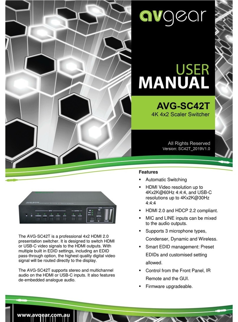
AVGear AVG-SC42T User manual

AVGear
AVGear avg-uhs41-v2 User manual
AVGear
AVGear AVG-SM-2.0 User manual
AVGear
AVGear AVG-UHC41A User manual

AVGear
AVGear AVG-DMM1616 User manual

AVGear
AVGear AVG-MS88-HDBT User manual

AVGear
AVGear MHD44 User manual
AVGear
AVGear AVG-DSS61 User manual
