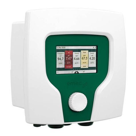
Emec DIN Digital CL User manual

1
Read carefully! ENGLISH Version
R1-09-04
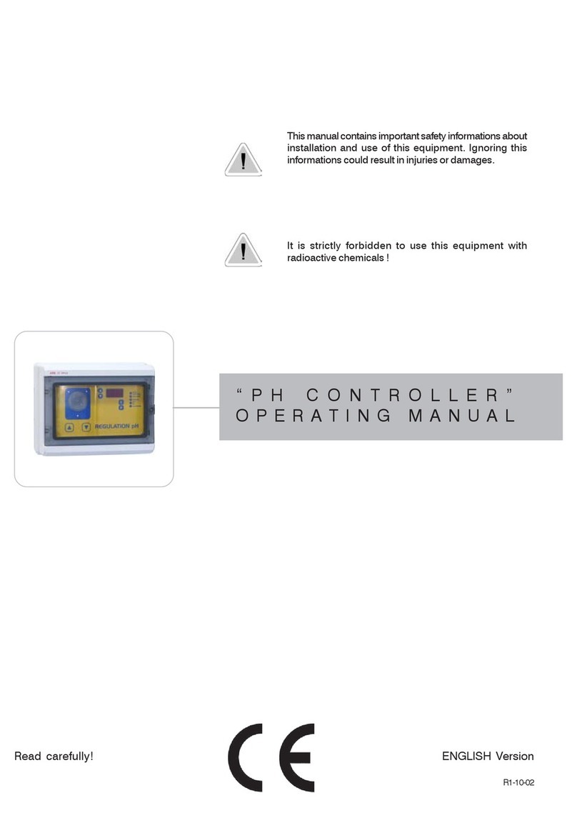
This manual contains important safety informations about
installation and use of this equipment. Ignoring this informations
could result in injuries or damages.
It is strictly forbidden to use this equipment with radioactive
chemicals!
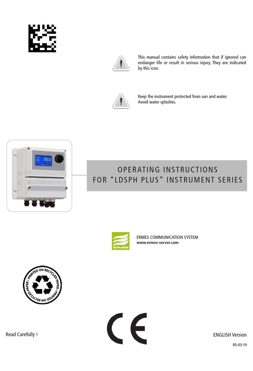
OPERATING MANUAL FOR
“DIN DIGITAL CL” CONTROLLER

Danger!
GENERAL SAFETY GUIDELINES
In emergencies the instrument should be switched off immediately! Disconnect the power cable
from the power supply!
When installing always observe local regulations!
Manufacturer is not liable for any unauthorized use or misuse of this product that may cause injury,
damage to persons and / or materials.
Caution! Instrument must be accessible at all times for both operating and servicing. Access must not be
obstructed in any way!
Feeder should be interlocked with a no-flow protection device to automatically shut-off the pumps
when there is no flow!
Pumps and accessories must be serviced and repaired by qualified and authorized personnel only!
Always discharge the liquid end before servicing the instrument!
Empty and rinse the liquid end before work on a pump which has been used with hazardous or
unknown chemicals!
Always read chemical safety datasheet!
Always wear protective clothing when handling hazardous or unknown chemicals!
Instrument must be operated / serviced by trained technicians only!
All connection operations must be performed while the instrument is not connected to main
supply!
Missed activation for Min/Max alarm and Maximum Dosing Alarm may cause hazardous overdosing!
NORME CE
EC RULES(STANDARD EC)
NORMAS DE LA CE
Direttiva Bassa Tensione
Low Voltage Directive
Directiva de baja tensión
Direttiva EMC Compatibilità Elettromagnetica
EMC electromagnetic compatibility directive
EMC directiva de compatibilidad electromagnética
2014/35/UE
2014/30/UE
⎬
⎬

3
Index
INDEX
GENERAL DESCRIPTION ................................................................. 4
CONTROL PANEL ........................................................................... 4
ELECTRICAL WIRINGS .................................................................... 5
VIEW ON MENU............................................................................. 6
SETTING SETPOINTS: 1)SETPN........................................................ 6
Out mA.......................................................................................... 7
CALIBRATION: 2)CALIB ................................................................. 8
DELAY: 3) Delay............................................................................. 9
RESERVED: 4) Reserv...................................................................... 9
PASSWORD SETUP: 1) New Pw...................................................... 10
STANDBY SETUP: 2) Stand.............................................................. 10
MANUAL WORKING MODE: 3) Serv. ............................................... 11
ERROR MESSAGES ......................................................................... 11
Warning: proportional mode operates on 100 or 150 seconds basis

4
GENERAL DESCRIPTION
“DIN Digital CL” measures and controls chlorine in industrial process. It is possible to set two ON/OFF setpoints and a current
signal for connecting a chart recorder or a metering pump. It is possible to set the current output on 0÷20 or 4÷20 mA. LCD
backlight display facilitates reading in high luminosity conditions. The instrument is cased into a plastic box for DIN mounting.
CONTROL PANEL
Into normal operating mode press “UP” or “DOWN” key for instrument’s details.
Use keyboard (up, down, left and right) to make a selection or change set values. Press the “RIGHT” key to go back in previous menu or cancel
entered data.
The “Enter” key confirms the selection.
Press “RIGHT” key for about 4 seconds to switch off the instrument (the display shows OFF). Repeat the sequence to return to the normal
operating mode.
To reset the instrument (restore default settings) unplug power supply and keeping pressed “UP” and “DOWN” keys, plug in power supply.The
instrument will show “Checksum Error- Press any key”. Press any key to continue.
Display
LCD backlight display
facilitates reading in high
luminosity conditions. It
provides constant indica-
tions regarding operating
conditions and equipment
status.
Introduction
A convenient keypad allows
easy and quick access to the
menu for easy programming
and calibrating operations.
Keyboard
“RIGHT” (ON/OFF - ESC) key “ENTER” key
E
UP” key “DOWN” key
9.99 Cl
1on 2--
SetPoint status. Ex:
“1ON” setpoint 1 is
active.
“2--” setpoint 2 is not
active.

5
ELECTRICAL WIRINGS:
1 - 2: Power Supply (230VAC* or 115VAC* or 24VAC*).
3-4: Setpoint 1 output - free contact.
5-6: Setpoint 2 output - free contact.
7-8: Chlorine Probe mod. ECL1/x . Max 10ppm. 7 (-VDC), 8(+VDC).
9-10: Chlorine Probe mod. ECL1/x . Max 10ppm. 9(GND), 10(Input Signal).
If used probe is mod. ECL4/5/6/7/12 connect as follows:
7-8: not connected.
9-10: Chlorine Probe ECL4/5/6/7/12. Max 10ppm. 9(Input Signal, red wire), 10(GND, black wire).
11-12: Current output (0÷20mA o 4÷20mA) proportional to read value. 11(-) ; 12 (+).
13-14-15-16: See the following paragraph.
“SEPR” CONFIGURATION.
The instrument is set to work without a proximity sensor. If needed, proximity sensor turns the instrument into stand-by mode
if there isn’t flow. Instrument’s display shows “NO FLOW”.
Connect “SEPR” to blocks 13(blue), 15(black), 16(brown). Connect together block 14 with block 13.
To work without a “SEPR” and with the same functionality use blocks 15 and 16 as a free contact. Connect together block
14 with block 13.
Using “SEPR” or the free contact, two instruments can be controlled. Connect block 14 and 15 from master instrument to
another instrument “Din Digital” (slave). Finally follows the previous described connections for the master instrument.
The instrument has not fuse protection.
* See instrument’s label.
Installation
1 2 3 4 5 6 7 8 9 10 11 12 13 14 15 16
ECL PROBE COLORS
7 white - 8 brown - 9 yellow - 10 green

6
VIEW ON MENU
Make connections and plug the instrument. Instrument’s version message on display confirms that the instrument is on. The
display shows also the probe reading status and if setpoints are active. Press “E” for about 4 seconds to enter into setup menu.
Note: During setup the instrument is in “Stand-by” mode. If user doesn’t press any key for one minute the instrument will
return to normal working mode.
To enter into setup menu, a password is needed. If this the first time that user enters into this menu or if the password is not
changed, simply press “E”. Use “UP” and “DOWN” keys to scroll.
“MAIN” menu is configured as follows:
1)Setup: This menu is divided into 1)Setpn ; 2)Calib ; 3)Delay.
2)Param: This menu is divided into 1)New Pw ; 2)Stand.
3)Serv.: service mode.
SETTING SETPOINTS: 1)SETPN
“Out 1” and “Out 2” are relay’s driven outputs. The instrument can be programmed to operate in “On/Off” mode or
“Proportional” mode.
“Proportional” mode can be selected in % between 0 and 100.
Select “SETUP” from “MAIN” menu. Select “SETPN” and press “E”. The display shows:
Setpoint
1) Out 1
Pressing “UP” or “DOWN” key the display will show in succession:
Setpoint
1) Out 1
Setpoint
2) Out 2
Setpoint
3) Out mA
Select the setpoint to set (Out 1 or Out 2) using “UP” and “DOWN” keys, press “E” to confirm. “Out mA” allows to set the
current output based on two Conductivity values. In the next example setpoint 1 (Out 1) has been set.
Installation

7
SETUP
The instrument shows:
1a) ->OFF
1.00Cl
Pressing twice “RIGHT” key the display will show:
1b) ->ON
0.00Cl
“1a)” and “1b)” are working range values. Every range is set by a value that operates relay output. Using default values, the
setpoint 1 will drive a pump that will increase the chlorine value. The pump will switch on for Cl values minor than 1.00Cl
and switch off when reaches 0.00Cl: this is the ON/OFF working mode. The difference between the two Cl (1.00 and
0.00) is called HYSTERESIS.
To avoid damaging the relay do not set Hysteresis under 0.20Cl.
PROPORTIONAL mode.The output relay is modulated (ON/OFF) depending on Cl values set in 1a) and 1b). Ex.: Proportional
mode between 1.00Cl (0%) and 0.50Cl (100%). In this way the relay will be on for values between 0.00Cl and 0.50Cl, it will
be on for values higher than 1.00Cl. For values between 1.00Cl and 0.50Cl the relay will be on or off depending on calculated
percentage.
The calculation is based on a 100 seconds time. If Cl reaches 0.60Cl the relay will be on for 80 seconds and off for 20 seconds.
To set the PROPORTIONAL functioning mode substitute percentual value to “ON” and “OFF”.
It is not possible to enter mixed values (ex.: 100% for SP1 and ON for SP2). In this case it will not possible
save them.
In proportional mode the instrument doesn’t show % values for setpoints status but only if they are on or off.
It is possible modify setpoint status (on,off, %) and setpoint values with RIGHT key on the function to modify and using “UP”
and “DOWN” key to change the value. Enter the value and save by pressing “E” to save.
Repeat sequence for setpoint 2 (OUT2).
Press “E” key to exit from setpoint setting. The display will show “SetPoint Saved” and it return to the
previous menu.
Out mA
This function allows to program the current output for driving a metering pump or a chart recorder.It is possible to program in
0÷20mA mode or 4÷20mA mode in the working range between 0 and 9.99ppm.The current output and the working range may
be modified. Ex.: it is possible to set 4mA at 9.99ppm and 20mA at 0ppm. In this case, if you connect a metering pump it will
dose at the maximum flow at 0ppm.The pump will reduce the flow when Cl decrease and it will stop at 9.99ppm. If you connect
a chart recorder, a graphic curve will be printed. Set minimum current value to 0ppm and maximum current value to 9.99ppm.
Use “UP” and “DOWN” keys to change these settings. Press “RIGHT” key to scroll through the options. Press “E” to confirm.

8
CALIBRATION: 2)CALIB
Choose “CALIB” from main menu. Display shows:
Calib
1)Zero
Press “UP” key. Display shows:
Calib
2) Slope
Zero calibration.
When display shows “1) Zero” press “E” to enter into zero calbration procedure. Display shows:
R 1.00Cl
C 0.00Cl
To calibrate it , if you are using an ECL4-6-7 probe, close water’s flow and wait for some minutes. If you are using an ECL1-
2-3-8 probe use flow-water without chlorine into probe holder or install an activated-carbon cartridge. If no one of these
methods is vailable, unscrew top probe connector or, if not present, disconnect probe’s green wire (signal wire).Wait until “R”
value is stable. ATTENTION: IT IS NOT NECESSARY THAT “R” VALUE WILL BE THE SAME OF “C” VALUE. Press “E”
to confirm. Display shows:
Calibr.
Success.
Slope calibration.
When display shows “2) Slope” press “E” to enter into slope calbration procedure. Display shows:
R 1.00Cl
C 0.00Cl
To obtain reliable reading results is necessary to calibrate the probe using a chlorine solution.Verify the plant’s chlorine value at
the end of probe holder using a colorimetric (DPD1) analysis sistem. Using “UP”and “DOWN” keys enter this value in “C” field.
Wait until “R” value is stable. ATTENTION: IT IS NOT NECESSARY THAT “R” VALUEWILL BE THE SAME OF “C”VALUE.
SETUP

9
SETUP
DELAY: 3) Delay
t’s possible to set an activation delay for each output when the instrument reaches the setpoint values. Default value is set to
0. Select “DELAY” from “SETUP” menu. The instrument will show:
OUT1
10 Sec.
Press “RIGHT” key.The instrument will show:
OUT2
5 Sec.
Delay time can be set from 0 (no delay) to 60 seconds. Press “E” to confirm. The display will show the confirmation message
“DELAYS SAVED”.

10
PARAM
PASSWORD SETUP: 1) New Pw
To avoid undesired access to the instrument a 4 number password may be set. Using “UP” or “DOWN” keys, from “Param”
menu choose “1) New Pw”, press “E” to confirm. The display shows:
NEW PW
-> 0 0 0 0
Use “UP” and“DOWN”keys to modify th first digit. Use “RIGHT” key to go on the next digit.Press “E” to confirm.The instrument
will show the new password for 2 seconds and then will return to the main menu.
STANDBY SETUP: 2) Stand
For a good electrodes polarization a delayed startup (every time the instrument is powered) may be set. Select “2)STAND”
from “Param” menu. The display will show:
STANDBY
-> 02 Sec.
It is possible to set the delay using “UP” and “DOWN” keys. The time can be set between 0 (no delay) to 60 seconds. Press
“E” to confirm. The display will show the confirmation message “Stand-by Saved” for 2 seconds.

11
SERV.
MANUAL WORKING MODE: 3) Serv.
This function allows to manual control the external relays contact (SP1 / SP2).
The display will show 1 or 2 to show the selected setpoint/output. The output status can be set “ON” or “OFF” using “UP”
key for SP1 and “DOWN” key for SP2. “ON” is the status of N.O contact closed and N.C. contact open. “OFF” is the status of
N.O. contact open and N.C. contact closed.
ERROR MESSAGES
If the display shows an error message, use the following table:
ERROR 1: Buffer solution error during calibration. Try again using a
different buffer solution.
ERROR 2: Buffer solution read error during calibration. Try again using a
different buffer solution.
ERROR 3: N/A
ERROR 4: Offset error. Verify sample and repeat procedure.
ERROR 5: Slope error. Verify sample and repeat procedure.

Disposal of end-of-life equipment by users
This symbol warns you not to dispose of the product with normal waste. Respect human
health and the environment by giving the discarded equipment to a designated collection
center for the recycling of electronic and electrical equipment. For more information visit the
online site.
When dismantling a pump please separate material types and send them according to local
recycling disposal requirements. We appreciate your efforts in supporting your local Recycle
Environmental Program. Working together we’ll form an active union to assure the world’s
invaluable resources are conserved.
Table of contents
Other Emec Controllers manuals
Popular Controllers manuals by other brands

Emerson
Emerson CBA730 Disassembly and Reassembly

Stanford Research Systems
Stanford Research Systems SR470 Operation manual

Mitsubishi Electric
Mitsubishi Electric FX3G-8AV-BD installation manual

Andover Controls
Andover Controls ACC EMX 150 installation guide

Realistic
Realistic 42-2105 owner's manual

OAK
OAK SCSI 4 user guide