Product overview and precautions
4
PRODUCT OVERVIEW AND PRECAUTIONS
The 375 Field Communicator supports HART and FOUNDATION fieldbus devices, letting
you configure or troubleshoot in the field. When using the 375 Field Communicator to
communicate with devices, follow all standards and procedures applicable to the
location. Failure to comply may result in equipment damage and/or personal injury. Be
sure to understand and comply with the following items:
• An IS-approved 375 Field Communicator can be used in Zone 0 (FM and CSA only),
Zone 1, or Zone 2, Division 1 and Division 2 locations (KL option only).
• An IS-approved 375 Field Communicator may be connected to loops or segments
that are attached to equipment located in Zone 0, Zone 1, Zone 2, Zone 20, Zone
21, Zone 22, Division 1 and Division 2 (KL option only).
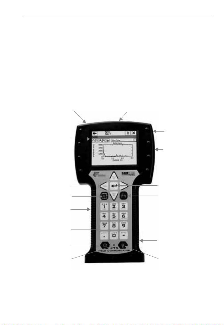
• The 375 Field Communicator includes an FSTN type LCD with touch-screen display,
a Nickel-Metal Hydride (NiMH) Battery Pack or Lithium Ion Power Module, an SH3
processor, memory components, and integral communication and measurement
circuitry.
• Three terminals are on the top of the 375 Field Communicator. Each red terminal is a
positive connection for its protocol, while the black terminal is a common terminal
shared by both protocols. An access door ensures that only one pair of terminals is
exposed at any one time. Several markings indicate which pair of terminals is for
which protocol.
• The touch screen must be contacted using blunt items only, preferably the stylus
included with the 375 Field Communicator. Using sharp instruments, such as
screwdrivers, can cause failure of the touch screen and void the warranty. Repair of
the touch screen requires replacement of the entire 375 Field Communicator display
assembly, which is possible only at an authorized service center.
• When connecting the 375 Field Communicator to an active FOUNDATION fieldbus
segment, ensure there is adequate spare current capacity to power the 375 Field
Communicator fieldbus circuits. The 375 Field Communicator draws approximately
17 mA.
• The infrared port and card reader let the 375 Field Communicator or its System Card
interface with a PC.
• Use the keypad or touch screen to enter data into the 375 Field Communicator.
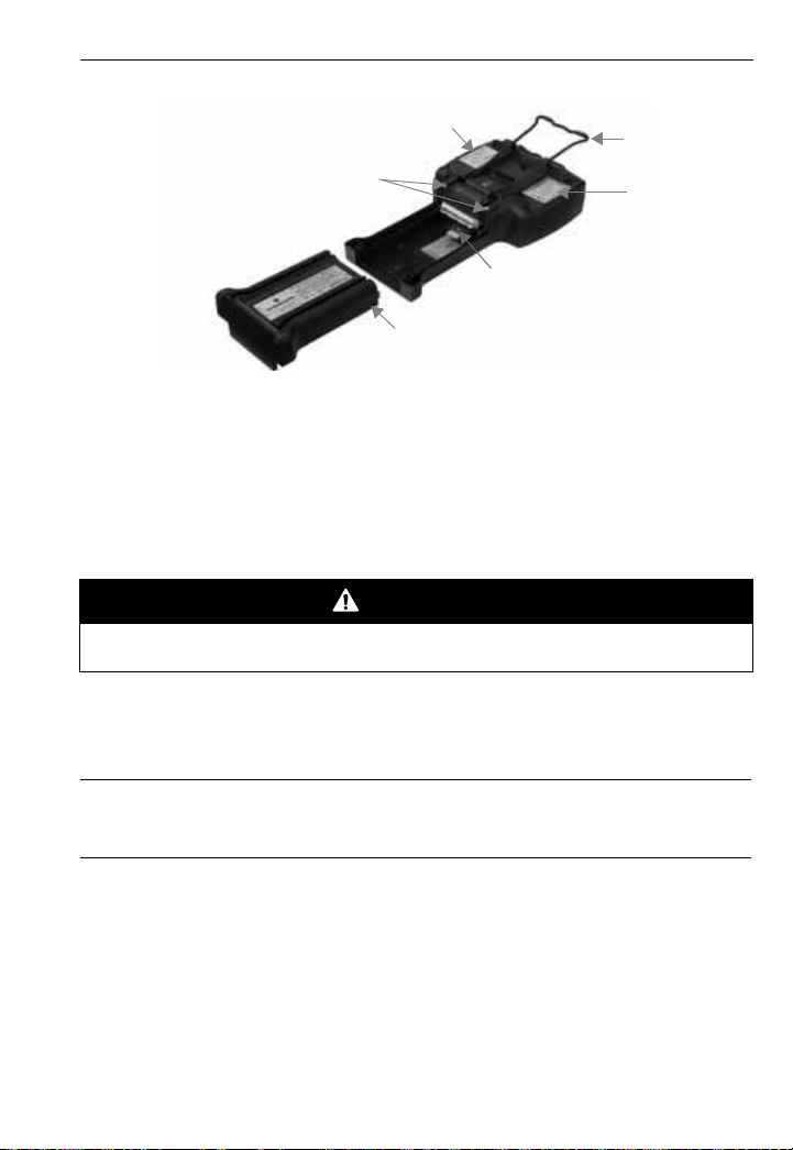
• An Expansion Module (EM) (labeled Expansion Module) is a removable memory
card that snaps into the Expansion Port. The EM can be removed or installed in a
hazardous area.
• Only the Expansion Module or Expansion Port Plug should be inserted into the
Expansion Port. System Cards/Secure Digital cards or other objects must not be put
into the Expansion Port. Failure to comply will void the IS approval and the warranty.
• The Secure Digital cards used in the System Port must be those supplied by the 375
Field Communicator manufacturer. Failure to comply will void the IS approval and
the warranty.
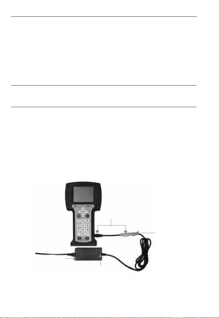
• The 375 Field Communicator supports two types of batteries: the NiMH Battery Pack
and the Lithium Ion Power Module. The NiMH Battery Pack has a black, 4-pin power
supply/charger connector, and the Lithium Ion Power Module has a green, 6-pin
connector. See Figure 1 for the location of the connector. In this manual, the term
“battery” is used to describe functionality that is common to both types of batteries.
Any differences are noted.
• When transporting a Lithium Ion Power Module, follow all applicable regulations.
• The battery can be removed and installed in a hazardous area environment.