Emerson Rosemount 375 User manual

User’s Manual
©2003, Emerson Process Management.
The contents of this publication are presented for
informational purposes only, and while every effort
has been made to ensure their accuracy, they are
not to be construed as warranties or guarantees,
express or implied, regarding the products or
services described herein or their use or applicability.
All sales are governed by our terms and conditions,
which are available on request. We reserve the right
to modify or improve the designs or specifications
of our products at any time without notice.
All rights reserved. The Emerson logo is a trademark
and service mark of Emerson Electric Company.
All other marks are the property of their
respective owners.
Emerson Process Management
Asset Optimization Division
12001 Technology Drive
Eden Prairie, MN 55344 USA
www.fieldcommunicator.com
Emerson Process Management
00375-0047-0001, rev B
Rosemount
00809-0100-4276
375 Field Communicator User’s Manual
REPLACE WITH NEW CODE


USER’SMANUAL
00375-0047-0001, Rev. C
February 2004 375 FIELD COMMUNICATOR
www.fieldcommunicator.com
375 FIELD COMMUNICATOR
© 2004 Emerson Process Management. All rights reserved.
The Emerson logo is a trademark and service mark of Emerson Electric Co.
AMS Suite is a trademark of Emerson Electric Co.
Rosemount and SMART FAMILY registered trademarks of Rosemount Inc.
Windows is a registered trademark of Microsoft Corporation in the United States and
other countries.
IrDA is a registered trademark of the Infrared Data Association.
FOUNDATION is a trademark of the Fieldbus Foundation.
HART is a registered trademark of the HART Communication Foundation.
Hitachi is a registered trademark of Hitachi America, Ltd.
All other marks are the property of their respective owners.
U.S. and foreign patent numbers are pending.
NOTICE
Read this User’s Manual before working with the Model 375 Field Communicator.
For personal and system safety, and for optimum product performance,
thoroughly understand the contents before using or servicing this product.
For equipment service needs, contact the nearest product representative.


www.fieldcommunicator.com
USER’SMANUAL
00375-0047-0001, Rev. C
February 2004 375 FIELD COMMUNICATOR
TABLE OF CONTENTS
SECTION 1
Introduction
Using this Manual. . . . . . . . . . . . . . . . . . . . . . . . . . . . . . . . . . . 1-1
SECTION 2
Learning the Basics
Overview . . . . . . . . . . . . . . . . . . . . . . . . . . . . . . . . . . . . . . . . . . 2-1
Safety Messages . . . . . . . . . . . . . . . . . . . . . . . . . . . . . . . . . . . 2-1
Installing the System Card and the battery pack . . . . . . . . . 2-2
Starting Up and Shutting Down . . . . . . . . . . . . . . . . . . . . . . . 2-3
Starting the 375 Field Communicator . . . . . . . . . . . . . . . . . . 2-4
Shutting down . . . . . . . . . . . . . . . . . . . . . . . . . . . . . . . . . . . . 2-4
Basic Features and Functions . . . . . . . . . . . . . . . . . . . . . . . . 2-5
Using the keypad . . . . . . . . . . . . . . . . . . . . . . . . . . . . . . . . . 2-6
On/off key. . . . . . . . . . . . . . . . . . . . . . . . . . . . . . . . . . . . . 2-6
Arrow navigation keys . . . . . . . . . . . . . . . . . . . . . . . . . . . 2-6
Enter key . . . . . . . . . . . . . . . . . . . . . . . . . . . . . . . . . . . . . 2-6
Tab key . . . . . . . . . . . . . . . . . . . . . . . . . . . . . . . . . . . . . . 2-6
Alphanumeric keypad . . . . . . . . . . . . . . . . . . . . . . . . . . . 2-7
Backlight adjustment key . . . . . . . . . . . . . . . . . . . . . . . . . 2-7
Function key. . . . . . . . . . . . . . . . . . . . . . . . . . . . . . . . . . . 2-8
Multifunction LED. . . . . . . . . . . . . . . . . . . . . . . . . . . . . . . 2-8
Using the touch screen . . . . . . . . . . . . . . . . . . . . . . . . . . . . . 2-8
Using the Soft Input Panel (SIP) keyboard . . . . . . . . . . . 2-9
Viewing The 375 Main Menu . . . . . . . . . . . . . . . . . . . . . . . . . . 2-9
Starting the HART application. . . . . . . . . . . . . . . . . . . . . . . 2-10
Starting the fieldbus application . . . . . . . . . . . . . . . . . . . . . 2-10

Table of Contents
TOC-2
Running the Settings menu . . . . . . . . . . . . . . . . . . . . . . . . . 2-10
About 375. . . . . . . . . . . . . . . . . . . . . . . . . . . . . . . . . . . . 2-10
Backlight. . . . . . . . . . . . . . . . . . . . . . . . . . . . . . . . . . . . . 2-11
Clock. . . . . . . . . . . . . . . . . . . . . . . . . . . . . . . . . . . . . . . . 2-11
Contrast . . . . . . . . . . . . . . . . . . . . . . . . . . . . . . . . . . . . . 2-11
Event capture . . . . . . . . . . . . . . . . . . . . . . . . . . . . . . . . . 2-12
License. . . . . . . . . . . . . . . . . . . . . . . . . . . . . . . . . . . . . . 2-13
Memory. . . . . . . . . . . . . . . . . . . . . . . . . . . . . . . . . . . . . . 2-13
Power . . . . . . . . . . . . . . . . . . . . . . . . . . . . . . . . . . . . . . . 2-13
Touch screen alignment. . . . . . . . . . . . . . . . . . . . . . . . . 2-14
Exit to the 375 Main Menu . . . . . . . . . . . . . . . . . . . . . . . 2-14
Communicating with a PC . . . . . . . . . . . . . . . . . . . . . . . . . . 2-14
IrDA communication with PCs . . . . . . . . . . . . . . . . . . . . 2-14
Listen For PC . . . . . . . . . . . . . . . . . . . . . . . . . . . . . . . . . 2-15
Transferring HART configurations using AMS Suite: Intelligent
Device Manager . . . . . . . . . . . . . . . . . . . . . . . . . . . . . . . 2-16
Easy Upgrade Programming Utility . . . . . . . . . . . . . . . . 2-16
Using the ScratchPad application . . . . . . . . . . . . . . . . . . . . 2-17
Create a new document . . . . . . . . . . . . . . . . . . . . . . . . . 2-18
Open an existing document . . . . . . . . . . . . . . . . . . . . . . 2-18
Enter text . . . . . . . . . . . . . . . . . . . . . . . . . . . . . . . . . . . . 2-18
Select text. . . . . . . . . . . . . . . . . . . . . . . . . . . . . . . . . . . . 2-18
Cut text. . . . . . . . . . . . . . . . . . . . . . . . . . . . . . . . . . . . . . 2-19
Copy text . . . . . . . . . . . . . . . . . . . . . . . . . . . . . . . . . . . . 2-19
Paste text . . . . . . . . . . . . . . . . . . . . . . . . . . . . . . . . . . . . 2-19
Undo text . . . . . . . . . . . . . . . . . . . . . . . . . . . . . . . . . . . . 2-19
Save a document . . . . . . . . . . . . . . . . . . . . . . . . . . . . . . 2-19
Save a copy . . . . . . . . . . . . . . . . . . . . . . . . . . . . . . . . . . 2-20
Delete a document . . . . . . . . . . . . . . . . . . . . . . . . . . . . . 2-20
Exiting ScratchPad. . . . . . . . . . . . . . . . . . . . . . . . . . . . . 2-20
Managing Storage. . . . . . . . . . . . . . . . . . . . . . . . . . . . . . . . . . 2-21
Types of storage . . . . . . . . . . . . . . . . . . . . . . . . . . . . . . . . . 2-21
Maintenance . . . . . . . . . . . . . . . . . . . . . . . . . . . . . . . . . . . . . . 2-22
Battery Information . . . . . . . . . . . . . . . . . . . . . . . . . . . . . . . 2-22
Checking the charge remaining . . . . . . . . . . . . . . . . . . . 2-22
Charging the battery. . . . . . . . . . . . . . . . . . . . . . . . . . . . 2-23
Removing the System Card and battery pack . . . . . . . . 2-23
Running a self test. . . . . . . . . . . . . . . . . . . . . . . . . . . . . . . . 2-24
Working in an Intrinsically Safe (IS) area. . . . . . . . . . . . . . . 2-24

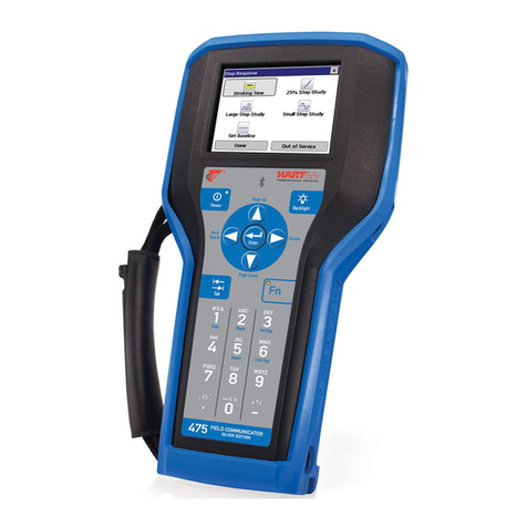
Table of Contents TOC-3
Waste disposal . . . . . . . . . . . . . . . . . . . . . . . . . . . . . . . . . . 2-24
SECTION 3
HART Functionality
Overview . . . . . . . . . . . . . . . . . . . . . . . . . . . . . . . . . . . . . . . . . . 3-1
Safety Messages . . . . . . . . . . . . . . . . . . . . . . . . . . . . . . . . . . . 3-1
Basic Features and Functions . . . . . . . . . . . . . . . . . . . . . . . . 3-2
Interpreting the HART icon . . . . . . . . . . . . . . . . . . . . . . . 3-2
Starting the HART Application . . . . . . . . . . . . . . . . . . . . . . . . 3-2
Using Fast Key sequences . . . . . . . . . . . . . . . . . . . . . . . . . . 3-2
Setting up Hot Key options . . . . . . . . . . . . . . . . . . . . . . . . . . 3-3
Executing Hot Key options . . . . . . . . . . . . . . . . . . . . . . . . . . 3-4
Removing Hot Key options one at a time . . . . . . . . . . . . . . . 3-4
Removing all Hot Key options. . . . . . . . . . . . . . . . . . . . . . . . 3-4
Working Offline. . . . . . . . . . . . . . . . . . . . . . . . . . . . . . . . . . . . . 3-5
Creating new configurations Offline . . . . . . . . . . . . . . . . . . . 3-5
Opening saved configurations Offline. . . . . . . . . . . . . . . . . . 3-7
Edit a saved configuration Offline . . . . . . . . . . . . . . . . . . 3-8
Copy a saved configuration Offline . . . . . . . . . . . . . . . . . 3-9
Send a saved configuration Offline . . . . . . . . . . . . . . . . . 3-9
Delete a saved configuration Offline . . . . . . . . . . . . . . . . 3-9
Rename a saved configuration Offline. . . . . . . . . . . . . . 3-10
Compare two saved configurations Offline . . . . . . . . . . 3-10
Working Online. . . . . . . . . . . . . . . . . . . . . . . . . . . . . . . . . . . . 3-11
Connecting to a HART loop . . . . . . . . . . . . . . . . . . . . . . . . 3-11
Viewing the Online menu. . . . . . . . . . . . . . . . . . . . . . . . . . . . 3-14
Viewing the Device Setup submenu . . . . . . . . . . . . . . . . . . 3-16
Process Variables (PV) . . . . . . . . . . . . . . . . . . . . . . . . . 3-16
Diagnostics and service. . . . . . . . . . . . . . . . . . . . . . . . . 3-16
Basic setup . . . . . . . . . . . . . . . . . . . . . . . . . . . . . . . . . . 3-17
Detailed setup . . . . . . . . . . . . . . . . . . . . . . . . . . . . . . . . 3-17
Review. . . . . . . . . . . . . . . . . . . . . . . . . . . . . . . . . . . . . . 3-17
Primary Variable (PV) . . . . . . . . . . . . . . . . . . . . . . . . . . . . . 3-18
Analog Output (AO). . . . . . . . . . . . . . . . . . . . . . . . . . . . . . . 3-18
Lower Range Value (LRV) . . . . . . . . . . . . . . . . . . . . . . . . . 3-18
Upper Range Value (URV) . . . . . . . . . . . . . . . . . . . . . . . . . 3-18
Viewing the Utility Menu . . . . . . . . . . . . . . . . . . . . . . . . . . . . 3-18

Table of Contents
TOC-4
Configuring the HART application . . . . . . . . . . . . . . . . . . . . 3-18
Changing the HART polling option. . . . . . . . . . . . . . . . . 3-18
Changing ignored status messages. . . . . . . . . . . . . . . . 3-20
Storage Cleanup. . . . . . . . . . . . . . . . . . . . . . . . . . . . . . . 3-20
Viewing available Device Descriptions . . . . . . . . . . . . . . . . 3-21
Simulating an online connection to a HART device. . . . . . . 3-21
Viewing HART diagnostics . . . . . . . . . . . . . . . . . . . . . . . . . 3-22
DC voltage measurement (HART terminals) . . . . . . . . . 3-22
Disconnecting from a HART device. . . . . . . . . . . . . . . . . . . 3-22
SECTION 4
Fieldbus Functionality
Overview . . . . . . . . . . . . . . . . . . . . . . . . . . . . . . . . . . . . . . . . . . 4-1
Safety Messages. . . . . . . . . . . . . . . . . . . . . . . . . . . . . . . . . . . . 4-1
Basic Features and Functions. . . . . . . . . . . . . . . . . . . . . . . . . 4-2
Link Active Scheduler (LAS) . . . . . . . . . . . . . . . . . . . . . . . . . 4-2
Interoperability. . . . . . . . . . . . . . . . . . . . . . . . . . . . . . . . . . . . 4-3
375 operation with other hosts. . . . . . . . . . . . . . . . . . . . . . . . 4-3
ST_REV. . . . . . . . . . . . . . . . . . . . . . . . . . . . . . . . . . . . . . . . . 4-3
Modes . . . . . . . . . . . . . . . . . . . . . . . . . . . . . . . . . . . . . . . . . . 4-4
Types of Modes . . . . . . . . . . . . . . . . . . . . . . . . . . . . . . . . 4-4
Locating Mode Parameters . . . . . . . . . . . . . . . . . . . . . . . 4-5
Changing Modes . . . . . . . . . . . . . . . . . . . . . . . . . . . . . . . 4-5
Permitted Modes . . . . . . . . . . . . . . . . . . . . . . . . . . . . . . . 4-5
Starting the Fieldbus Application . . . . . . . . . . . . . . . . . . . . . . 4-6
Working Online . . . . . . . . . . . . . . . . . . . . . . . . . . . . . . . . . . . . . 4-7
Connecting to a fieldbus loop . . . . . . . . . . . . . . . . . . . . . . . . 4-7
Bench hook-up . . . . . . . . . . . . . . . . . . . . . . . . . . . . . . . . . 4-9
Field hook-up . . . . . . . . . . . . . . . . . . . . . . . . . . . . . . . . . 4-10
Displaying the Live Device List . . . . . . . . . . . . . . . . . . . . . . 4-11
Displaying the Block List . . . . . . . . . . . . . . . . . . . . . . . . . . . 4-12
Working with Device Blocks. . . . . . . . . . . . . . . . . . . . . . . . . 4-13
Parameter Functionality . . . . . . . . . . . . . . . . . . . . . . . . . 4-13
Changing and sending parameter data . . . . . . . . . . . . . 4-14
Running methods (e.g. calibrations, sensor trim, diagnostic
etc.). . . . . . . . . . . . . . . . . . . . . . . . . . . . . . . . . . . . . . . . . 4-15
Displaying Device status . . . . . . . . . . . . . . . . . . . . . . . . 4-15

Table of Contents TOC-5
Other Block List selections . . . . . . . . . . . . . . . . . . . . . . . . . 4-15
Detail Menu . . . . . . . . . . . . . . . . . . . . . . . . . . . . . . . . . . 4-15
Changing the I/O block schedule. . . . . . . . . . . . . . . . . . 4-16
Displaying advanced features . . . . . . . . . . . . . . . . . . . . 4-17
Utility . . . . . . . . . . . . . . . . . . . . . . . . . . . . . . . . . . . . . . . . . . . . 4-17
Polling . . . . . . . . . . . . . . . . . . . . . . . . . . . . . . . . . . . . . . 4-17
Viewing Installed Fieldbus Device Descriptions. . . . . . . 4-18
Fieldbus Diagnostics . . . . . . . . . . . . . . . . . . . . . . . . . . . . . . . 4-18
Disconnecting from a Fieldbus Device . . . . . . . . . . . . . . . . 4-19
SECTION 5
Troubleshooting
Overview . . . . . . . . . . . . . . . . . . . . . . . . . . . . . . . . . . . . . . . . . . 5-1
Troubleshooting suggestions . . . . . . . . . . . . . . . . . . . . . . . . 5-1
Loops. . . . . . . . . . . . . . . . . . . . . . . . . . . . . . . . . . . . . . . . 5-2
Sample values . . . . . . . . . . . . . . . . . . . . . . . . . . . . . . . . . 5-3
Error and Status Messages. . . . . . . . . . . . . . . . . . . . . . . . . . . 5-5
Required information for technical assistance . . . . . . . . . . . 5-9
Contacting Technical Support Personnel. . . . . . . . . . . . 5-10
APPENDIX A
Reference Information
Processor and Memory Specifications . . . . . . . . . . . . . . . . . A-1
Microprocessor . . . . . . . . . . . . . . . . . . . . . . . . . . . . . . . . . . . A-1
Memory. . . . . . . . . . . . . . . . . . . . . . . . . . . . . . . . . . . . . . . . . A-1
Internal Flash. . . . . . . . . . . . . . . . . . . . . . . . . . . . . . . . . . A-1
System Card . . . . . . . . . . . . . . . . . . . . . . . . . . . . . . . . . . A-1
RAM. . . . . . . . . . . . . . . . . . . . . . . . . . . . . . . . . . . . . . . . . A-1
Expansion Module . . . . . . . . . . . . . . . . . . . . . . . . . . . . . . A-1
Physical Specifications . . . . . . . . . . . . . . . . . . . . . . . . . . . . . . A-1
Weight. . . . . . . . . . . . . . . . . . . . . . . . . . . . . . . . . . . . . . . . . . A-1
Display . . . . . . . . . . . . . . . . . . . . . . . . . . . . . . . . . . . . . . . . . A-1
Keypad . . . . . . . . . . . . . . . . . . . . . . . . . . . . . . . . . . . . . . . . . A-2
Power Supply Specifications . . . . . . . . . . . . . . . . . . . . . . . . . A-2
Power supply voltage. . . . . . . . . . . . . . . . . . . . . . . . . . . . A-2
Battery . . . . . . . . . . . . . . . . . . . . . . . . . . . . . . . . . . . . . . . A-2
Battery operating time . . . . . . . . . . . . . . . . . . . . . . . . . . . A-2
Power Supply/Charger. . . . . . . . . . . . . . . . . . . . . . . . . . . A-2

Table of Contents
TOC-6
Connection Specifications. . . . . . . . . . . . . . . . . . . . . . . . . . . .A-2
Battery Charger . . . . . . . . . . . . . . . . . . . . . . . . . . . . . . . . A-2
HART and Fieldbus Communication . . . . . . . . . . . . . . . . A-2
Personal Computer. . . . . . . . . . . . . . . . . . . . . . . . . . . . . . A-2
Environmental Specifications . . . . . . . . . . . . . . . . . . . . . . . . .A-3
Usage. . . . . . . . . . . . . . . . . . . . . . . . . . . . . . . . . . . . . . . . A-3
Charge . . . . . . . . . . . . . . . . . . . . . . . . . . . . . . . . . . . . . . . A-3
Storage. . . . . . . . . . . . . . . . . . . . . . . . . . . . . . . . . . . . . . . A-3
Storage without batteries . . . . . . . . . . . . . . . . . . . . . . . . . A-3
Enclosure rating . . . . . . . . . . . . . . . . . . . . . . . . . . . . . . . . A-3
Shock . . . . . . . . . . . . . . . . . . . . . . . . . . . . . . . . . . . . . . . . A-3
Ordering Information . . . . . . . . . . . . . . . . . . . . . . . . . . . . . . . .A-4
Spare Parts List. . . . . . . . . . . . . . . . . . . . . . . . . . . . . . . . . . . A-5
APPENDIX B
Approval Information
Overview . . . . . . . . . . . . . . . . . . . . . . . . . . . . . . . . . . . . . . . . . .B-1
Approved Manufacturing locations. . . . . . . . . . . . . . . . . . . . .B-1
European Directive Information . . . . . . . . . . . . . . . . . . . . . . .B-1
Electro Magnetic Compatibility (89/336/EWG). . . . . . . . . B-1
ATEX Directive (94/9/EC) (KL option only). . . . . . . . . . . . B-1
Other important guidelines . . . . . . . . . . . . . . . . . . . . . . . . B-1
Hazardous Locations Certifications (KL option only). . . . . .B-2
North American Certifications . . . . . . . . . . . . . . . . . . . . . . . . B-2
Factory Mutual (FM). . . . . . . . . . . . . . . . . . . . . . . . . . . . . B-2
Canadian Standards Association (CSA). . . . . . . . . . . . . . B-2
European Certifications . . . . . . . . . . . . . . . . . . . . . . . . . . . . . B-3
ATEX Intrinsic Safety . . . . . . . . . . . . . . . . . . . . . . . . . . . . B-3
HART Intrinsically Safe electrical parameters . . . . . . . . . B-3
Foundation fieldbus . . . . . . . . . . . . . . . . . . . . . . . . . . . . . B-3
Label Drawings . . . . . . . . . . . . . . . . . . . . . . . . . . . . . . . . . . . . .B-4
Approval Drawing. . . . . . . . . . . . . . . . . . . . . . . . . . . . . . . . . . .B-6
Glossary . . . . . . . . . . . . . . . . . . . . . . . . . . . . . . . . . .G-i
Index . . . . . . . . . . . . . . . . . . . . . . . . . . . . . . . . . . . . . I-1

www.fieldcommunicator.com
USER’SMANUAL
00375-0047-0001, Rev. C
February 2004 375 FIELD COMMUNICATOR
SECTION 1INTRODUCTION
USING THIS
MANUAL The sections in this manual provide information on
connecting and operating the 375 Field
Communicator.
Section 2: Learning the Basics contains
information on settings, types of storage, IrDA®
communication, using ScratchPad, maintenance,
managing files and storage.
Section 3: HART Functionality contains
information on starting the HART®application,
establishing communication with connected HART
devices, and configuring the HART application.
Section 4: Fieldbus Functionality contains
information on starting the fieldbus application,
establishing communication with connected
fieldbus devices, viewing the live list, block lists,
and configuring the fieldbus application.
Section 5: Troubleshooting provides solutions to
the most common 375 Field Communicator
operating problems.
Appendix A: Reference Information provides
physical, functional, and performance
specifications.
Appendix B: Approval Information contains
Hazardous Location Certifications, European
directive information, and approval drawings.

Introduction
1-2

www.fieldcommunicator.com
USER’SMANUAL
00375-0047-0001, Rev. C
February 2004 375 FIELD COMMUNICATOR
SECTION 2LEARNING THE BASICS
OVERVIEW This section provides instructions on basic features
and functions of the 375 Field Communicator. It
also provides instructions on starting, configuring
the settings, using ScratchPad, maintaining, and
shutting down the 375 Field Communicator.
SAFETY
MESSAGES Procedures and instructions in this section may
require special precautions to ensure the safety of
the personnel performing the operation.
Information that raises potential safety issues is
indicated by a warning symbol ( ). Refer to the
following safety messages before performing an
operation preceded by this symbol. Other warning
messages can be found in the Troubleshooting
section of this manual.
IMPORTANT NOTICE
Ensure the battery pack and the 375 Field Communicator are properly aligned during assembly
to prevent damage to the connector pins.
IMPORTANT NOTICE
During assembly/disassembly:
Do not pull up on the battery pack as this could damage the power supply connector.
Do not pull up on the System Card as this could damage the card or the System Card socket.

Learning the Basics
2-2
INSTALLING
THE SYSTEM
CARD AND
THE BATTERY
PACK
1.Place the 375 Field Communicator face down on
a level, secure surface; see Figure 2-1.
2.Lock the stand into the hanger position. To pivot
past the stand position, squeeze the stand
together near the hinge.
Figure 2-1. Back side of the 375 Field Communicator
WARNING
Contact with the touch screen should be made by blunt items only, preferably the stylus included
with the 375 Field Communicator. The use of sharp instruments, such as screwdrivers, can
cause failure of the touch screen interface.
WARNING
Initiating a Re-Flash initiates reinstallation of the system software from the System Card. This
should only be performed under the direction of technical support personnel.
Battery pack
retaining screws
Battery pack
System Card
Stand Assembly
Battery pack charge
indicator button

Learning the Basics 2-3
3.With the battery pack removed, place the
System Card, with the card contacts facing up,
on the main unit System Card guide ribs (located
directly below the battery pack connector). Insert
the System Card until it is firmly in place.
4.With the main unit still face down, ensure the
tops of the two battery pack retaining screws are
flush with the top of the battery pack.
5.Install the battery pack by aligning the sides of
the battery pack and main unit and carefully
sliding the battery pack forward until it is secure.
If the battery pack and main unit are not properly
aligned, the connector pins can be damaged.
6.Tighten the two battery pack retaining screws
until they are secure (do not overtighten). The
tops of the screws should now be close to flush
with the stand groove.
STARTING UP
AND
SHUTTING
DOWN
Prior to using the 375 Field Communicator without
the charger/power supply, fully charge the battery
pack. A full charge is indicated by a solid green
light on the charger/power supply. Charging may
take up to two hours. The 375 Field Communicator
may be used while charging. Before operating the
375 Field Communicator, ensure:
• The 375 Field Communicator is not damaged.
• The battery pack is fully seated.
• All screws are sufficiently tightened.
• An Expansion Module (EM) or Expansion Port
Plug is in place.
• The communication terminal recess is free of dirt
and debris.

Learning the Basics
2-4
Starting the
375 Field
Communicator
Press and hold the on/off key until the Multifunction
LED flashes to indicate the unit is powering
(approximately two seconds). See Figure 2-2 for
on/off key location.
During start-up, the 375 Field Communicator will
automatically install any software upgrades
available on the System Card. Once complete, the
375 Main Menu will be displayed. After starting the
375 Field Communicator, you can choose to:
• Launch the HART or FOUNDATION fieldbus
Applications (if licensed)
• Configure/view Settings
• Enter Listen for PC
• Launch the ScratchPad application
Shutting down While applications are open, the on/off key is
disabled. You must exit to the 375 Main Menu
before using the on/off key. To shut down the 375
Field Communicator press and hold the on/off key
until the display turns off (approximately three
seconds).

Learning the Basics 2-5
BASIC
FEATURES
AND
FUNCTIONS
Figure 2-2. 375 Field Communicator diagram
Backlight
adjustment key
IrDA interface
(top)
Touch screen
display
HART and fieldbus
communication
terminals (top)
Expansion po
rt
(side)
Enter key
Function key
(for multiple-key
combination functionality
)
Alphanumeric keypad
Power supply/charge
r
connection (side)
Multifunction LED
On/off key
Navigation keys
(four arrow keys)
Tab key
Stylus
(back)

Learning the Basics
2-6
Using the
keypad The 375 Field Communicator keypad and touch
screen have nearly total functional redundancy.
On/off key
The on/off ( ) key is used to power on and off the
375 Field Communicator.
You can also power the 375 Field Communicator
off by simultaneously pressing the backlight
adjustment key and the function key until the
display turns off. This is a mechanism by which the
power down is accomplished in the hardware
(similar to removing the power to a PC using a
switch). This is not the recommended way of
shutting off the 375 Field Communicator.
Arrow navigation keys
Four arrow navigation keys allow you to move
through the menu structure of the applications.
Press the right arrow navigation key ( ) to
navigate further into the menu.
Enter key
The enter ( ) key allows you to perform the
focused item or to complete an editing action and
does not navigate you through the menu structure.
For example, if you have the Cancel button in
focus (highlighted) when you push the enter key,
you will be choosing to cancel out of that particular
window.
Tab key
The tab ( ) key allows you to move between
selectable controls.

Learning the Basics 2-7
Alphanumeric keypad
The alphanumeric keypad allows you select to
both letters, digits, and other characters, such as
punctuation marks. It can perform a selection of
options and data entry in either numeric or
alphanumeric modes. The 375 Field
Communicator will automatically determine the
mode depending upon the input necessary for the
particular field.
When in alphanumeric mode, to enter text press
the desired keypad button in quick repetition to
scroll through the options to achieve the
appropriate letter or number. For example, to type
the letter Z, press the 9 key quickly four times; see
Figure 2-3.
Figure 2-3. Keypad button functionality example
Backlight adjustment key
The backlight adjustment ( ) key allows you to
adjust the intensity of the display. There are four
different settings. Intensity impacts the battery life
of the 375 Field Communicator. Expect a shorter
battery life for higher intensities; see “Backlight” on
page 2-11 for settings.

Learning the Basics
2-8
Function key
The function ( ) key allows you to enable
alternate functionality on select keys. The grey
characters on the keys indicate the alternate
functionality. When enabled, the orange
multifunction LED light will appear and an
indication button can be found on the Soft Input
Panel (SIP). If the function key is enabled, press
the key again to disable the functionality.
The alternate function on the Tab and
alphanumeric 5 key (insert) will be activated in
future releases of the 375 Field Communicator
software.
Multifunction LED
The multifunction LED allows you to recognize
when the 375 Field Communicator is in various
states; see Table 2-1.
Table 2-1. Multifunction LED
Using the
touch screen The touch screen display allows you to select and
enter text by touching the window. Tap the window
once to select a menu item or to activate a control.
Double-tap to move further into the menu level.
NOTE
All instructions in this manual are written for the
touch screen.
Multifunction LED Processing indication
Green The 375 Field Communicator is on.
Flashing Green The 375 Field Communicator is in
power saving mode. The display is off.
Green and Orange The Function key is enabled.
Flash green and orange The on/off button has been held down
long enough for power up.
Other manuals for Rosemount 375
4
Table of contents
Other Emerson Cell Phone manuals

Emerson
Emerson 475 User manual

Emerson
Emerson AMS Trex User manual

Emerson
Emerson 475 User manual

Emerson
Emerson Rosemount 375 User manual

Emerson
Emerson Rosemount 375 User manual

Emerson
Emerson AMS Trex Device Communicator User manual

Emerson
Emerson 475 Manual

Emerson
Emerson Rosemount 375 User manual

Emerson
Emerson Rosemount 375 User manual

Emerson
Emerson AMS Trex User manual