Type 1805P
4
150 psi (10,3 bar). The individual spring range of your
relief valve is stamped on the nameplate. System
operation within these limitations does not eliminate the
possibility of damage from external sources or debris in
the gas line. The valve should be inspected for damage
after any overpressure condition.
Vents
an explosion hazard under enclosed
installations. Install remote vent lines to
If remote venting is necessary, install remote vent
lines in both the outlet of the pilot and the outlet of
the main valve. Remove the screen, if one is present
in the outlet, and install remote vent lines in the
outlet openings. The vent lines must have the largest
practical diameter and be as short as possible with a
minimum number of bends or elbows.
Startup
With proper installation completed and system
equipment properly adjusted, close any vent valves,
and slowly open the upstream shutoff valve while using
pressure gauges to monitor pressure.
Adjustment
Note
Each unit is factory set for the pressure specied on
your order. The allowable spring range is stamped
on the nameplate. If a pressure setting beyond the
indicated range is required, substitute the appropriate
spring. Be sure to label the valve to indicate the new
pressure range.
Pilot Adjustment
If set pressure adjustment is necessary, monitor
the inlet pressure with a gauge during the
adjustment procedure.
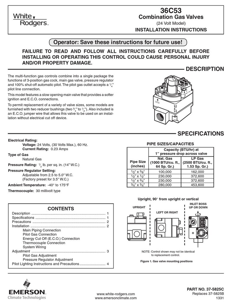
If it is necessary to vent the unit, install an exhaust
line into the 1/4 NPT pilot exhaust (port A, Figure 2).
This exhaust line may be vented directly into the main
valve outlet or separately to atmosphere. In either
case, the vent line or stack diameter should be as
large as practical with a minimum number of bends or
other restrictions.
A vent line or stack must be located to avoid venting
gas near buildings, air intakes, or any hazardous
location. The line or stack opening must be protected
against debris, weather, condensation, insects, or
anything else that might clog it.
The set pressure of the unit is adjusted by changing the
pilot spring compression. The pressure setting of each
unit is factory set. If adjustment is necessary, refer to
the Adjustment section for the procedures.
Overpressure Protection
Relief ranges are from 10 to 150 psig (0,69 to 10,3 bar).
The maximum inlet pressure including build-up, is
Before installing, inspect the main valve and pilot for
any shipment damage and any foreign material. Make
sure that the valve is oriented so that pipeline ow is
in the same direction as indicated by the arrow cast on
the body. Use a good grade of pipe compound on the
pipe threads, but not on the body threads.
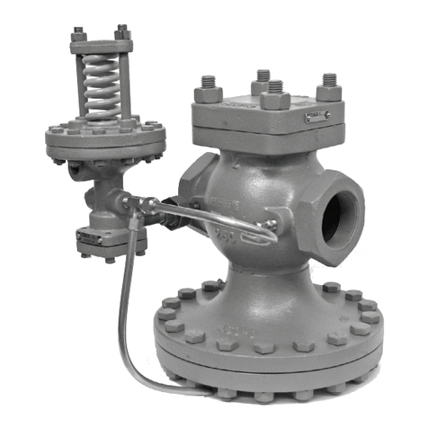
A typical pilot mounting position is shown in Figure 1.
To achieve other desired control and exhaust
connections, the pilot may be rotated on the pipe nipple
(port C, Figure 2).
The Type 1805P requires a control line attached to the
1/4 NPT control connection (port D, Figure 2). The
control line should be 1/4-inch (6,4 mm) outer diameter
pipe or tubing or larger and connected to a straight
run of inlet piping. If the pipeline contains dirt, install a
lter in the control line and/or upstream piping.
an explosion hazard under enclosed
is remotely vented to a safe location.
than the upper limit of the set pressure
!
WARNING
!
WARNING
