manuals.online logo
Brands
  1. Home
  2. •
  3. Brands
  4. •
  5. Emerson
  6. •
  7. Control Unit
  8. •
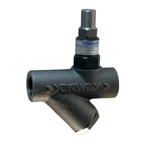
  9. Emerson YARWA 151 Series User manual

Emerson YARWA 151 Series User manual

Other Emerson Control Unit manuals

Emerson Fisher V260 User manual

Emerson

Emerson Fisher V260 User manual

Emerson Fisher 161 Series User manual

Emerson

Emerson Fisher 161 Series User manual

Emerson PACSystems VersaMax IC200CMM020 User manual

Emerson

Emerson PACSystems VersaMax IC200CMM020 User manual

Emerson Crosby JOS-E Series User manual

Emerson

Emerson Crosby JOS-E Series User manual

Emerson NEOTECHA KR Series Quick guide

Emerson

Emerson NEOTECHA KR Series Quick guide

Emerson Daniel 700 Series Quick start guide

Emerson

Emerson Daniel 700 Series Quick start guide

Emerson 1805 Series User manual

Emerson

Emerson 1805 Series User manual

Emerson Vanessa 30000 Series User manual

Emerson

Emerson Vanessa 30000 Series User manual

Emerson FRM-2 Manual

Emerson

Emerson FRM-2 Manual

Emerson 581 Series Installation instructions

Emerson

Emerson 581 Series Installation instructions

Emerson Tartarini V Series User manual

Emerson

Emerson Tartarini V Series User manual

Emerson unidrive m User manual

Emerson

Emerson unidrive m User manual

Emerson ASCO 290 Series User manual

Emerson

Emerson ASCO 290 Series User manual

Emerson Fisher Design GX Series User manual

Emerson

Emerson Fisher Design GX Series User manual

Emerson Rosemount 68 Series User manual

Emerson

Emerson Rosemount 68 Series User manual

Emerson CROSBY BP SERIES Guide

Emerson

Emerson CROSBY BP SERIES Guide

Emerson FieldQ QC4124 V DC User manual

Emerson

Emerson FieldQ QC4124 V DC User manual

Emerson Daniel 700 Series User manual

Emerson

Emerson Daniel 700 Series User manual

Emerson Anderson Greenwood 9300 Series User manual

Emerson

Emerson Anderson Greenwood 9300 Series User manual

Emerson TX7 User manual

Emerson

Emerson TX7 User manual

Emerson KEYSTONE F635 Installation instructions

Emerson

Emerson KEYSTONE F635 Installation instructions

Emerson Daniel 762 User manual

Emerson

Emerson Daniel 762 User manual

Emerson CROSBY Guide

Emerson

Emerson CROSBY Guide

Emerson Enardo ES-665-HF User manual

Emerson

Emerson Enardo ES-665-HF User manual

Popular Control Unit manuals by other brands

Seitz 14A80 user manual

Seitz

Seitz 14A80 user manual

Wilo RS485 Installation and operating instructions

Wilo

Wilo RS485 Installation and operating instructions

Becker CentralControl CC41 Commissioning Instruction

Becker

Becker CentralControl CC41 Commissioning Instruction

SICK CDB650 operating instructions

SICK

SICK CDB650 operating instructions

Panduit NetKey NKP5E88M Series installation instructions

Panduit

Panduit NetKey NKP5E88M Series installation instructions

MX Options Concentric Petite Fitting instructions

MX

MX Options Concentric Petite Fitting instructions

Clean Water Systems Fleck 2510 Installation & start?up guide

Clean Water Systems

Clean Water Systems Fleck 2510 Installation & start?up guide

Fairchild FSB44104A user guide

Fairchild

Fairchild FSB44104A user guide

LEGRAND Wattstopper LMIN-104 installation instructions

LEGRAND

LEGRAND Wattstopper LMIN-104 installation instructions

PMK ATT10BNCS instruction manual

PMK

PMK ATT10BNCS instruction manual

Tektronix TDS3FFT user manual

Tektronix

Tektronix TDS3FFT user manual

Woodward easYgen Technical manual

Woodward

Woodward easYgen Technical manual

Balluff BNI EIP-502-105-R015 user guide

Balluff

Balluff BNI EIP-502-105-R015 user guide

NXP Semiconductors TWR-LS1021A Getting started

NXP Semiconductors

NXP Semiconductors TWR-LS1021A Getting started

Advantech PCM-3117 Startup manual

Advantech

Advantech PCM-3117 Startup manual

Danfoss MCO 101 manual

Danfoss

Danfoss MCO 101 manual

Moons' Lin Engineering R701P user manual

Moons'

Moons' Lin Engineering R701P user manual

Aventics RV1 operating instructions

Aventics

Aventics RV1 operating instructions

manuals.online logo
manuals.online logoBrands
  • About & Mission
  • Contact us
  • Privacy Policy
  • Terms and Conditions

Copyright 2025 Manuals.Online. All Rights Reserved.

© 2017 Emerson. All Rights Reserved.Emerson.com/FinalControl
How to install repair capsules in Series 151 steam traps
YARWAY PROCESS THERMOSTATIC STEAM TRAPS
SerieS 151
OPERATION
Series 151 steam traps are designed for use
in process heat exchange applications. A filled
thermal element actuates the pilot valve. The
main valve/cage assembly is actuated by fluid
dynamics. Discharge is basically cyclic in
nature and occurs near steam temperature.
The pilot valve can discharge condensate
continuously, but will close when dry steam
reaches the trap.
WARNING
Hot discharge from this product may cause severe
burns. Discharge must be piped away or directed
so that persons in the vicinity are not endangered.
This product must be isolated, vented and cool to
the touch before repairing or inspecting.
VCIOM-05067-EN17/01
INSTALLATION
Before installing the trap, blow out the piping
thoroughly to remove loose scale and dirt. Use
pipe dope or tape sparingly when attaching the
trap to the pipe.
Observe the pressure limitations and flow
direction shown on the trap label. Install the
trap in an accessible location for inspection
and maintenance, below the equipment being
drained (see Fig. 1).
STRAINER
Series 151 traps have built-in screen. Install a
separate Yarway series 921 Wye strainer with
blowdown valve.
FIGURE 1
Recommended installation
Full pipe size of
equipment outlet
¾” Min. for 151
1” Min for 151H
Isolated valves
(Gate or Ball)
Test valve
(Gate or Ball)
Union
Series 151 - A trap
921 Strainer
20" min
Series 151-A (Angle) Series 151-I (In-Line)
SPECIFICATION
ANSI Class 300
Maximum Operating Pressure: 300 psig (21 bar)
Maximum Operating Temperature: 500F (260C)
Minimum differential: 1 psi (.07 bar)
Maximum test pressure: 740 psig (51 bar)
Nominal Capacity
100 psi (7 bar) near saturation temperature.
Series 151: 4500 lb/hr (2040 kg/hr).
Series 151H: 8500 lb/hr (3850 kg/hr).
End Connections
¾”, 1” NPT-ANSI B1.20.1
¾”, 1” Socketwelding-ANSI B16.11
Position
The trap may be installed as shown in Fig. 1
with discharge downward or with bonnet on the
side. For freezeproof installation, it should be
positioned vertically or on its side. Make certain
that the arrow on the body agrees with the
direction of flow.
Discharge piping
To avoid excessive back pressures, discharge
piping should be amply sized. For short
discharge lines, (up to equivalent length of 10
ft.) use pipe equal to trap size. If several traps
discharge to a common return line or manifold,
size the line to prevent buildup of excessive
back pressure during the simultaneous
discharge of all traps. All piping and fittings
downstream of 151H traps must be 1” or
larger.
2
YARWAY PROCESS THERMOSTATIC STEAM TRAPS
SerieS 151
MAINTENANCE
Inspect the trap and clean the strainer screen
during the first month of operation. Inspect and
clean the trap every 6 to12 months.
Inspect the trap and clean the screen
Close the valve ahead of the trap and close the
downstream valve. Allow the trap to cool and
slowly open the test valve. Sudden opening of
the test or strainer valve can cause damage to
the filled thermal element. Open the strainer
blowdown slowly. Loosen the bonnet. The
strainer screen fits tightly on the bonnet screen
guide. Remove the bonnet and screen to expose
the working parts of the trap.
Caution
Be certain the pressure in the trap is relieved
before removing the bonnet.
Clean the trap
Inspect the following parts for wear or oxide
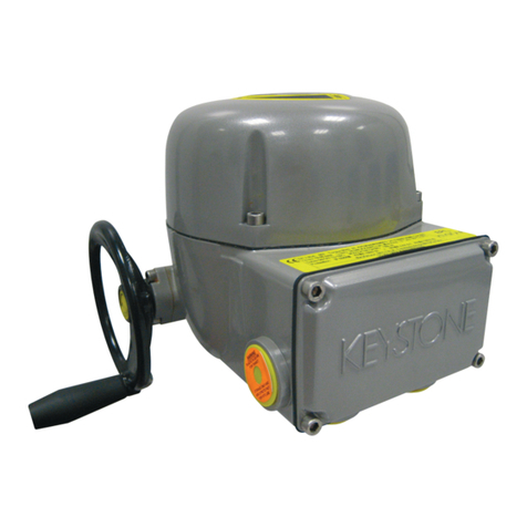
deposit: the seat (4), the outside surface of the
cage (3) and the inside bore of the bonnet (2).
Do not remove the seat unless it is damaged.
Clean dirt or oxides from inspected parts using
a commercial solvent. Do not scrape surfaces
and do not use emery paper or other abrasive
material.
If internals are damaged or worn, renewal
kits are available from your local distributor. A
renewal kit consists of a seat (4), seat gasket
(5), preassembled cage assembly (3), bonnet
gasket (8) and strainer screens (6). Bonnets (2)
are available separately.
Reassembly
Lubricate the bonnet (2) threads and both sides
of the bonnet gasket (8) with Loctite Stainless
Steel PST sealant or equivalent. Place the
screen on the bonnet screen guide. Place
the cage assembly (3) in the body. Thread the
bonnet into the body making sure that the cage
enters the bonnet and the screen fits properly.
Recommended bonnet torque: 150-160 ft-lb
(203-217 Nm).
Installation of renewal kit
Remove the old seat. Clean gasketing surfaces
in the body to remove dirt. Use a new seat
gasket (5). Lubricate the seat (4) threads with
suitable high temperature lubricant such
as Loctite Stainless Steel PST sealant or
equivalent. Thread the seat (4) into the body.
Recommended seat torque: 60-65 ft-lb (81-88
Nm). Install cage assembly (3), screen (6) and
gaskets (5)(8) in accordance with reassembly
instructions.
Start-up
Slowly open the isolating valve ahead of the
trap. This allows the filled thermal element
to warm up and minimize water hammer and
shock. Slowly open the downstream line valve.
Close the test valve.
TROUBLESHOOTING
Problem Potential Remedy
Trap remains
closed or
provides
inadequate
drainage.*
a. Check the upstream and downstream isolation and check valves to assure they are open.
b. Check the strainer for clogging. Blow down the separate strainer and clean the screen
within the trap.
c. Dirt or oxide deposits. Clean the trap internal cage plugged with dirt. Replace cage.
d. Poor Installation-the trap is too hot. Be certain the trap is installed bellow equipment
being drained, using uninsulated piping to condense untrapped steam and provide
sufficient subcooling to open the main valve.
e. Trap may be undersized. Check requirements against trap rating.
CAUTION: Follow the maintenance instructions when attempting to disassemble and service
the trap.
Trap remains
open and
is blowing
steam; is not
shutting off.*
a. Dirt on the seat of the cage and/or pilot valve, or oxide deposits between the cage and the
bonnet. Clean the trap.
b. Damaged or worn pilot. Replace the cage with a new repair kit.
c. Condensate load is too low. Pilot capacity is adequate to remove condensate. Trap is not
full open, just operating on pilot flow only. The trap is not faulty.
CAUTION: Follow the maintenance instructions when attempting to disassemble and service
the trap.
*Dirt can lodge between the bonnet and cage. This unlikely event could result in the cage remaining open or
closed. Disassemble and remove dirt. Check to be sure screen is in place and undamaged.
3
2
1B
7
3
8
4
5
7
2
6
5
4
3
1A
8
6
YARWAY PROCESS THERMOSTATIC STEAM TRAPS
SerieS 151
PARTS AND MATERIALS
Item Part Material
1A Body 151 angle
Body 151S/SN angle
ASME SA-105, Carbon steel
ASME SA182 316L Stainless steel
1B Body 151 In-line ASME SA 182 F11, Cr. Mo.
0.15% Maximum Carbon
1B Body 151S/SN In-line ASME SA182 316L Stainless steel
2Bonnet ASTM A-582 416 Stainless steel
31Cage assembly Stainless steel
41Seat Stainless steel
51Gasket, seat Monel®
61Screen 18-8 Stainless steel
7Nameplate 302 Stainless steel
81Gasket, bonnet Monel®Teflon®coated
SERIES 151 ANGLE SERIES 151 IN-LINE
NOTES:
1. Denotes available repair kit.
Neither Emerson, Emerson Automation Solutions, nor any of their affiliated entities assumes responsibility for the selection, use or maintenance of any product.
Responsibility for proper selection, use, and maintenance of any product remains solely with the purchaser and end user.
Yarway is a mark owned by one of the companies in the Emerson Automation Solutions business unit of Emerson Electric Co. Emerson Automation Solutions, Emerson,
and the Emerson logo are trademarks and service marks of Emerson Electric Co. All other marks are the property of their respective owners.
The contents of this publication are presented for informational purposes only, and while every effort has been made to ensure their accuracy, they are not to be
construed as warranties or guarantees, express or implied, regarding the products or services described herein or their use or applicability. All sales are governed by
our terms and conditions, which are available upon request. We reserve the right to modify or improve the designs or specifications of such products at any time without
notice.
Emerson.com/FinalControl
YARWAY PROCESS THERMOSTATIC STEAM TRAPS
SerieS 151
NOTE
Any malfunction of this product must be reported to the service department.
Repare made to the product by unauthorized personnel will void the warranty.
Right to know laws and OSHA standard 29CFR (1910.1200)
Material Safety Data Sheets on the following Yarway products:
Valves, Steam traps and Strainers
The OSHA Hazard Communication Standard 29CFR 1910.1200, states that the standard does not
apply to “articles.” The standard defines an article as:
“A manufactured item formed to a specific shape or design for a particular use which does not
release or otherwise expose an employee to a hazardous chemical under normal conditions of use.”
The above named products fall within the definition of an “article”, no Material Safety Data Sheets
are available or are required. Our product is manufactured as an “end product.”
If the product is a weld end the following applies.
WARNING
Materials used in manufacture of Yarway products are considered in a stable condition when shipped.
However, under certain conditions purchasers could create potential hazardous conditions by their
future operations.
CAUTION
Welding, cutting, burning, machining or grinding of this product can generate toxic dust and fumes of
potentially hazardous ingredients. The dust or fumes can cause irritation of the respiratory tract, nose,
throat, skin and eyes. It may cause temporary or permanent respiratory disease in a small percentage
of exposed individuals. Use moderate ventilation when grinding or welding. Avoid breathing dust, fumes
or mist. Avoid prolonged skin contact with dust or mist. Maintain dust levels below OSHA and ACGIH
levels. Use protective devices. Wash hands thoroughly after contact with dust before eating or smoking.