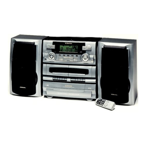
Emerson RS1008 User manual

HOMEAUDIOSYSTEM
withCD PLAYER,DIGITALTUNER,
3-WAYTOWERSPEAKERS
and POWEREDSUBWOOFER
RS1008
OWNER'SMANUAL
Visitourweb siteatwww.emersonradio.com
RS1008_ib042303.p65 23/4/2003, 14:5131

1
TO PREVENT FIRE OR SHOCK HAZARD, DO NOT USE THIS PLUG WITH AN EXTENSION
CORD, RECEPTACLE OR OTHER OUTLET UNLESS THE BLADES CAN BE FULLY
INSERTED TO PREVENT BLADE EXPOSURE. TO PREVENT FIRE OR SHOCK HAZARD,
DO NOT EXPOSE THIS APPLIANCE TO RAIN OR MOISTURE.
IMPORTANTSAFETYINSTRUCTIONS
1.) Read these instructions.
2.) Keep these instructions.
3.) Heed all warnings.
4.) Follow all instructions.
5.) Do not use this apparatus near water.
6.) Clean only with dry cloth.
7.) Do not block any ventilation openings. Install in accordance with the manufacturer’s instructions.
8.) Do not install near any heat sources such as radiators, heat registers, stoves, or other apparatus
(including amplifiers) that produce heat.
9.) Do not defeat the safety purpose of the polarized or grounding-type plug. A polarized plug has two blades
with one wider than the other. A grounding type plug has two blades and a third grounding prong. The
wide blade or the third prong are provided for your safety. If the provided plug does not fit into your outlet,
consult an electrician for replacement of the obsolete outlet.
10.) Protect the power cord from being walked on or pinched particularly at plugs, convenience receptacles,
and the point where they exit from the apparatus.
11.) Only use attachments / accessories specified by the manufacturer.
12.) Unplug this apparatus during lightning storms or when unused for long periods of time.
13.) Refer all servicing to qualified service personnel. Servicing is required when the apparatus has been
damaged in any way, such as power-supply cord or plug is damaged, liquid has been spilled or objects
have fallen into the apparatus, the apparatus has been exposed to rain or moisture, does not operate
normally, or has been dropped.
14.) This appliance shall not be exposed to dripping or splashing water and no object filled with liquids such
as vases shall be placed on the apparatus.
15.) Do not overload wall outlet. Use only power source as indicated.
16.) Use replacement parts as specified by the manufacturer.
17.) The product may be mounted to a wall only if recommended by the manufacturer.
18.) Upon completion of any service or repairs to this product, ask the service technician to perform
safety checks.
CAUTION
!
CAUTION
RISK OFELECTRICSHOCK
DONOTOPEN
The lightning flashwitharrowhead
symbol,withinanequilateraltriangle
isintented toalertthe userto
the presenceofuninsulated
‘dangerousvoltage’withinthe
product’s enclosurethatmaybe
ofsufficientmagnitudetoconstitute
arisk ofelectricshock topersons
The exclamation pointwithin
an equilateraltriangleisintended
toalertthe usertothe presence
ofimportantoperating and
maintenance(servicing)instructions
inthe literatureaccompanying
the appliance.
WARNING:TOREDUCETHERISK
OFELECTRICSHOCKDONOT
REMOVE COVER(ORBACK),NO
USERSERVICEABLEPARTSINSIDE
REFERSERVICINGTOQUALIFIED
SERVICEPERSONNEL.
RS1008_ib042303.p65 23/4/2003, 14:511
2
Thankyou forpurchasing thisEmerson floorstanding homeaudiosystemwithCD player,digital
tuner,3-waytowerspeakers,and powered subwoofer.
Pleaseread thisinstruction manualcompletelyand carefullytomakesureyou getthe maximum
benefitoutofall the advanced featureswehavebuiltintothissystem.
Thissystemwasinperfectworking orderwhen itleft ourfactory.If you haveanyproblemwiththe
setup oroperation ofthissystem,do notreturnittothe retail store.Pleasecall the Emerson
CustomerServiceHotline,toll free,at800-898-9020.
Once again, thanks for purchasing this Emerson audio product.
For future reference, record the serial number in the space provided.
Model No: RS1008
Serial No:
RS1008_ib042303.p65 23/4/2003, 14:512

3
•Avoidinstalling thisunitinplacesexposed to
directsunlightorclosetoheatradiating
appliancessuchaselectricheaters,on top of
otherstereoequipmentthatradiatestoomuch
heat, placeslacking ventilation ordustyareas,
placessubjecttoconstantvibration and/or
humidormoistareas.
•Donotattempttoclean thisunitwithchemical
solventsasthismightdamage the finish.Use
aclean drycloth.
CLASS 1LASERPRODUCT
CLASS 1LASERPRODUCT
APPAREILÁLASERDECLASSE 1
PRODUCTOLASERDECLASE 1
CAUTION
INVISIBLELASERRADIATION
WHENOPENAND INTERLOCKS
DEFEATED.
AVOIDEXPOSURETOBEAM
ThisproductcontainsalowpowerLaserDevice.
FCC INFORMATION
Thisequipmenthasbeen tested and found tocomplywiththe limitsforaClass Bdigitaldevice,
pursuanttoPart15 ofthe FCC Rules.Theselimitsaredesigned toprovide reasonableprotection
againstharmfulinterferenceinaresidentialinstallation.Thisequipmentgenerates,uses,and can
radiateradiofrequency energyand,ifnotinstalled and used inaccordancewiththe instructions,
maycauseharmfulinterferencetoradiocommunications.However,thereisno guarantee that
interferencewill notoccurinaparticularinstallation.If thisequipmentdoescauseharmful
interferencetoradioortelevision reception,whichcan be determined byturning the equipmentoff
and on,the userisencouraged totrytocorrectthe interferencebyone ormoreofthe following
measures:
•Reorientorrelocatethe receiving antenna.
•Increasethe separation between the equipmentand receiver.
•Connectthe equipmentintoan outleton acircuitdifferentfromthattowhichthe receiveris
connected.
•Consultthe dealeroran experienced radio/TVtechnician forhelp.
ThisdevicecomplieswithPart15 ofthe FCC Rules.Operation issubjecttothe following two
conditions:
(1)Thisdevicemaynotcauseharmfulinterference,and
(2)Thisdevicemustacceptanyinterferencereceived,including interferencethatmaycause
undesired operation.
IMPORTANTNOTES
•Operatecontrolsand switchesasdescribed
inthe manual.
•Beforeturning ‘On’the power,makecertain
thatpowercordisproperlyinstalled.
•StoreyourCDs,inacoolarea toavoid
damage fromheat.
•When moving the set, be suretofirst
disconnectthe powercord.
RS1008_ib042303.p65 23/4/2003, 14:513

4
PREPARATIONFORUSE
UNPACKING AND SET-UP
• Carefully remove all of the components and confirm that you have the following:
1.) Center Stand with Subwoofer x 1.
2.) Tower Speakers x 2.
3.) Receiver/CD Player Unit x 1 (with FM Antenna Wire attached).
4.) Remote Control x 1.
5.) Speaker Cables x 2.
6.) Subwoofer Connection Cable x 1.
• Position the Center Stand with Subwoofer unit in the desired location. Note that this system requires two
AC outlets. If you do not have two outlets available in the desired location you may have to use a UL
Listed multi-outlet surge protector, or power-strip, not included.
• Note that there are two exposed screws on the front side of the Center Stand. These screws are aligned
with two matching “keyholes” on the back of the Receiver/CD Player unit. Hold the Receiver/CD player
unit facing you with two hands. Position the Receiver/CD Player against the stand so that the two mounting
screws on the stand fit into the two “keyholes” on the back of the Receiver/CD Player.
Hint: It’s easier to do this if you are looking down from the top as you position the Receiver/CD
Player against the center stand. When the two mounting screws are inside the two keyholes, slide
the Receiver/CD Player unit slightly downward to lock the unit in place. If it should become necessary
to remove the Receiver/CD Player unit from the center stand, slide the unit upward slightly to
‘unlock’ it, and then pull the unit gently toward you.
• After you have mounted the Receiver/CD Player unit on the Center Stand unwind the FMAntenna Wire
that is attached to the back panel of the Receiver/CD Player unit and let the wire hang freely against the
back of the Center Stand.
IMPORTANT: Save the carton and all packing materials until the system has been completely
set up and is operating properly. The retail store cannot accept the return of this system without
the original carton and all packing materials.
BACKVIEWFRONTVIEW
KEY HOLES HANGINGSCREWS
RS1008_ib042303.p65 23/4/2003, 14:514

5
CONNECTING THE SPEAKERS
Note: The Receiver CD/Player unit must be mounted on the Center Stand before you connect the
speakers to the back panel.
TOWER SPEAKERS
Locate the color-coded speakers cables. The speaker terminals on the back of the tower speakers are
‘Spring Type’. Depress the red lever on the back of each tower speaker and insert the bare end of the red
wire into the terminal. Release the red lever to lock the wire in place. Follow the same procedure to connect
the black wire to the black terminal of each tower speaker.
BACK PANEL
Connect the other end of the color-coded speaker cables to the speaker terminals on the back panel of the
Receiver/CD Player unit. The terminals on the back of the Receiver/CD Player unit are ‘Lever Type’. Set the
4 plastic levers to their ‘Down’ (Open) position. Insert the bare wires from the left tower speaker into the color
coded terminals and then set the levers back to the ‘Up’ (Closed) position to lock the wires in place. Repeat
this procedure to connect the wires from the right tower speaker to the right terminals.
Note: Be sure to make the connections correctly. If the speakers are connected incorrectly the sound
may be ‘muddy’ or distorted.
L+
L-
Black Wire
Red Wire
R-
R+
Red
Black
Red
Red
Black
Black Wire
Red Wire
RS1008_ib042303.p65 2/5/2003, 9:405

6
SUBWOOFER
Locate the Subwoofer Connection Cable. This is a black cable with black colored plugs on each end. Connect
one end of the Subwoofer cable to the AUDIO IN jack on the back of the subwoofer. Connect the other end
of the Subwoofer Connection Cable to the SUBWOOFER jack on the back panel of the Receiver/CD Player
unit.
CABLE ROUTING GUIDES
For a neater appearance, and to avoid too many dangling wires, we have provided upper and lower plastic
cable routing guides which are attached to the back panel of the Center Stand. If desired you may snap the
covers off these cable guides, place the wires in the channels, and then snap the covers back on.
SUBWOOFERBACKPANELRECEIVER/CD BACKPANEL
CONNECTIONCABLE
AUDIOINJACK
SUBWOOFER
JACK
CABLEROUTINGGUIDES
RS1008_ib042303.p65 23/4/2003, 14:516

7
INSTALLING THE REMOTE CONTROL BATTERIES
Locate the Remote Control unit. The battery compartment is on the back side of the remote. Press down on
the battery door locking tab to open and remove the door.
Insert two fresh “AA” alkaline batteries in the battery compartment, then replace the battery door. Be sure to
insert the batteries according to the polarity (+ / – ) markings inside the battery compartment. If the batteries
are inserted incorrectly the remote control will not work.
BATTERYPRECAUTIONS
Followtheseprecautionswhen using batteriesinthisdevice:
1.)Useonlythe sizeand type ofbatteriesspecified.
2.)Besuretofollowthe correctpolaritywhen installing the batteriesasindicated inthe battery
compartment. Reversed batteriesmaycausedamage tothe device.
3.)Donotmixdifferenttypesofbatteriestogether(e.g.Alkaline and Carbon-Zinc)orold
batterieswithfreshones.
4.)If the deviceisnottobe used foralong period oftime,removethe batteriestoprevent
damage orinjuryfrompossiblebatteryleakage.
5.)Donottrytorecharge batteriesnotintended tobe recharged;theycan overheatand
rupture.(Followbatterymanufacturer’s directions.)
RS1008_ib042303.p65 23/4/2003, 14:517

8
POWER SOURCE
This system requires two 120V 60 Hz AC outlets.
The small plug from this AC adapter must be connected
to the DC Input Jack on the back of the Receiver/CD Player
as shown
The power source for the stereo receiver/CD player unit is
a separate AC adapter, included. This adapter is located
inside the bottom of the cabinet.
The power cord from the AC Adapter is then connected to a standard 120V 60 Hz AC outlet.
The active subwoofer has its own AC power cord that should be connected directly to a standard 120V 60 Hz
AC outlet.
Both of these AC power cords have polarized plugs with one blade wider than the other. These polarized
plugs are designed for connection to polarizedAC outlets with
one wide slot and one narrow slot. These plugs can only be
inserted in polarized outlets and they will only fit one way. This
is a safety feature designed to protect you from electric shock.
If you find that the plugs do not fit in your outlets you may have
outdated non-polarized outlets. Do not try to defeat the safety
feature by filing the wider blade to make it fit, or by using an
adapter.
If the plugs of this system will not fit in your AC outlets you should contact a qualified, licensed electrician to
replace your outdated outlets with polarizedAC outlets.
AC Plug
AC Outlet
DC 15VINPUT
JACK
DC 15VCABLE
AC/DC ADAPTER
ACCORD
120V/60Hz
ACOUTLETS
RS1008_ib042303.p65 23/4/2003, 14:518

9
SYSTEM CONTROLS
There are two ways to operate this system. You may use the remote control or you may use the touch sensor
control panel that is located above the CD door.All of the main system controls are found in both locations,
however the remote handset has some additional controls that are not on the touch sensor control panel.
As you read this manual, unless otherwise specified, the operations described can be performed either with
the remote control or with the touch panel. If an operation can only be performed with the remote control, the
instructions for that operation will clearly indicate “REMOTE CONTROL ONLY”.
USING THE REMOTE CONTROL UNIT
To use the remote control the IR transmitter on the top edge of the remote handset should be pointed in the
direction of the Remote Sensor on the front panel of the main unit. The remote control has an effective
operating range of approximately 15 feet, and an operating angle of approximately 15° to the left or right of
‘dead center’.
When not in use the Remote Control unit may be placed in the remote
control rest area on top of the subwoofer.
The Remote Control unit will also operate the system while it is in its rest
position.
REMOTECONTROLUNIT
RS1008_ib042303.p65 2/5/2003, 9:399

10
LOCATIONOFCONTROLSAND INDICATORS
1.)LCDDisplay/TouchPanel.
2.)CDDoorOpen/Close.
3)POWEROn/Off.
4.)VOLUME.
5.)SKIP/TUNER.
6.)POWER‘On’Indicator.
7.)PLAY/PAUSE .
8.)STOP.
9.)CD.
10.)EQ.
11.)TUNER/BAND.
12.)X-BASS.
13.)AUX.
14.)PROGRAM.
15.)VOLUME.
16.)SKIP/TUNER.
17.)RemoteSENSOR.
FRONTPANEL
BACK PANEL
3
1
2
4
5
6
7
8
9
10
11
12
13
14
15
16
17
18
19
20.)SUBWOOFEROutJack.
21.)AUXINJacks.
22.)Stand Mounting Holes.
23.)FMWireAntenna.
24.)DC 15VInputJack.
25.)Left SpeakerTerminals.
26.)RightSpeakerTerminals.
22
20
21
22
23
24
25
26
LEFT SIDEPANEL
18.)PHONES Jack.
RIGHTSIDEOFDISPLAY
19.)RESETButton.(Inside pinhole)
RS1008_ib042303.p65 23/4/2003, 14:5110

11
SUBWOOFERAND SPEAKER
1.)DetachableSpeakerGrille.
2.)POWERON/OFF Button (Subwoofer).
3.)SubwooferPower‘On’Indicator.
4.)VOLUMEControl(Subwoofer).
5.)Subwoofer.
6.)FMWireAntenna.
7.)DC PowerPlug ofAC/DC AdapterforConnecting to
MainUnit.
8.)WireGrooveforDressing All Cablesinside.
9.)AUDIOINJack.
10.)ACPowerCordofSubwoofer.
11.)ACPowerCordofAC/DC AdapterforMainUnit.
7
8
9
10
11
1
2
5
4
3
6
RS1008_ib042303.p65 23/4/2003, 14:5911

12
REMOTECONTROL
TUNER/
BAND
CD
X-BASS EQ
MODE SLEEP
TIMER
AUX
REPEAT
POWER
MUTE
VOL
VOL
PRESET
STOP
PLAY/
PAUSE
SNOOZE
1 2
3
5
4
8
7
6
9 0
10
ST/MONO
PROGRAM
1.)EQButton.
2.)X-BASS Button.
3.)SNOOZEButton.
4.)TIMERButton.
5.)MODEButton.
6.)SLEEP Button.
7.)PLAY/PAUSE Button.
8.)TUNING–/RevSkip-SEARCH Button.
9.)CD Button.
10.)MUTEButton.
11.)VOL(Volume)Button.
12.)TUNER/BAND Button.
13.)TUNING+/FwdSkip-SEARCH Button.
14.)VOL(Volume)Button.
15.)STOPButton.
16.)AUXButton.
17.)REPEATButton.
18.)PRESETButton.
19.)ST/MONOButton.
20.)POWERButton.
21.)CD DOOROpen/CloseButton.
22.)PROGRAMButton.
23.)+10 Button.
24.)Number0-9Buttons.
1
2
3
4
5
6
7
8
9
10 11 12
13
14
15
16
17
18
19
20
21
24 23 22
RS1008_ib042303.p65 23/4/2003, 14:5112

13
MULTIFUNCTIONLCD DISPLAY
1
2
3 4 5 6 7 8
9
10
11
1.)TouchPanelFunction Controls.
2.)CLOCKIndicator.
3.)AM/PMIndicators.
4.)REPEAT/REPEATALL Indicators.
5.)TIMERON/OFF Indicators.
6.)SNOOZEIndicator.
7.)SLEEP Indicator.
8.)MUTEIndicator.
9.)ST(FMStereo)Indicator.
10.)Multi-DataIndicators.
11.)PresetEQIndicators.
RS1008_ib042303.p65 23/4/2003, 14:5113

14
OPERATINGINSTRUCTIONS
• Make sure that the AC power cords from both the Receiver/CD Player unit and the Subwoofer
are connected to 120V 60Hz AC outlets.
• Make sure that you have installed batteries in the Remote Control unit.
• Make sure that both the tower speakers and the subwoofer are correctly connected to the
appropriate terminals and jacks on the back of the Receiver/CD Player unit.
GENERAL CONTROLS
POWER Button
Press the POWER button on the touch panel or the remote control to switch the system ‘On’ and ‘Off’.
VOLUME / Buttons
Press these buttons on the touch panel or on the remote to increase or decrease the volume. When the
volume level is adjusted the volume level indicator appears on the display.
Preset Equalizer (EQ) Button
This system includes a 4 mode electronic preset equalizer that adjusts the tone for popular types of music.
Press the EQ button on the touch panel or the remote to select the following EQ modes:
POP ROCK JAZZ DISCO FLAT (EQ ‘Off’). The selected setting appears in the main
display momentarily and then disappears. However the POP/ROCK/JAZZ or DISCO indicators will remain
in the display until you change to a new setting or shut the EQ ‘Off’ by selecting the FLAT mode.
X-BASS
Press the X-BASS button on the touch panel or the remote to switch the X-BASS circuit ‘On’ or ‘Off”.
The X-BASS ON or OFF indicator momentarily flashes in the display to confirm your selection.
Subwoofer POWER ON /OFF Button (on Subwoofer only)
Press this button to switch the active subwoofer ‘ON ’ or ‘OFF ’. The Subwoofer Power ‘On’ indicator
lights when the subwoofer is ‘On’.
RS1008_ib042303.p65 23/4/2003, 14:5114

15
Subwoofer VOLUME Level Control (on Subwoofer only)
After switching the Subwoofer POWER Button ‘On’, rotate the Subwoofer VOLUME level control to adjust
the volume of the subwoofer speaker.
Note: The volume of the subwoofer speaker cannot be controlled by the VOLUME / Buttons on
the touch panel or the remote control.
MUTE Button (Remote Control unit only)
Press the MUTE button on the Remote Control unit to temporarily shut off the sound. The MUTE indicator
appears in the display. To cancel Mute and restore the sound, press the MUTE button again; or press the
VOLUME / buttons. The MUTE indicator disappears.
ST/MONO-Stereo/Mono Button (Remote Control unit only)
Press this button to switch between FM Stereo and FM Mono reception modes. If FM Stereo reception is
noisy or weak try switching to the FM Mono mode. Reception on weak stations will normally improve although
the sound will no longer be in Stereo.
RS1008_ib042303.p65 23/4/2003, 14:5115

16
SETTING THE CLOCK
When the AC cord from the Receiver/CD Player unit is connected to
the AC outlet for the first time, the time display will begin flashing.
This flashing is your indication that power has been interrupted, the
display is incorrect and the time must be reset. The flashing will
stop when you set the time.
1.) Press the POWER button to switch the system ‘On’. The display will briefly indicate “HELLO”. Then
press the MODE button (Remote Control unit only) to enter the time setting mode. The CLOCK indicator
appears in the display.
2.) Press the PROGRAM button. The HOUR digits begin to flash.
Press the or buttons to set the correct hour, AM or PM.
3.) Press the PROGRAM button again. The MINUTE digits begin
to flash. Press the or buttons to set the correct minute.
4.) When the correct time appears on the display press the PROGRAM button once more. The display
stops flashing and the clock begins to run.
Notes:
• The correct time appears on the display when the unit is in the Power Off/Standby mode.
• Time setting can be done also when the unit is in Power Off/Standby mode.
RS1008_ib042303.p65 23/4/2003, 14:5116

17
LISTENING TO RADIO
Reminder: Unless otherwise specified you may use the controls on the touch panel display or on the
remote control to perform all of the following operations.
1.) Press the POWER button to turn the Receiver/CD Player unit
‘On’. The touch panel display lighting turns on. Also press the
Subwoofer POWER button, on the Subwoofer only, to turn the
Subwoofer ‘On’ if necessary.
2.) Press the TUNER/BAND button to select the Tuner function if
necessary. An AM or FM radio frequency will appear on the
display. If necessary press the TUNER/BAND button again to
switch betweenAM and FM bands.
3.) Press the or buttons to tune to the frequency of your desired station as follows:
•Manual Tuning
Repeatedly press the or buttons until the display shows the frequency of the desired station. Use
this method when tuning in weak or distant stations. If the you tune to an FM Stereo station the ST
indicator will appear in the display.
•Automatic Tuning
Depress the or buttons until the display begins to move, then release the buttons. The tuner will
search up or down for the next strong station and stop on that station. Repeat this procedure until the
tuner stops on the desired station.
4.) Adjust the main VOLUME, EQ, X-BASS, and Subwoofer VOLUME controls as desired.
5.) When you are finished listening press the POWER button to shut the system ‘Off’. The touch panel
display lighting goes off and the display again shows the correct time.
Note: It is not necessary to manually shut off the Subwoofer power each time you switch the main
power off. However if you do not plan to use the system again for a long period of time it is
recommended to manually switch the Subwoofer power ‘Off’.
Note: The system will remember the last station you were listening to before you shut the power off,
plus the volume level, EQ setting, X-Bass setting and FM mode setting. It will automatically return to
the same station and same setting when the power is switched ‘On’ again.
Antenna Information
FM
Make sure that the lead wire FMAntenna, attached to the FMAntenna screw terminal on the back panel of
the Receiver/CD Player unit, is fully unwound and allowed to hang freely down from the back of the unit.
AM
The AM ferrite bar antenna is located inside the cabinet of the Receiver/CD Player unit. If AM reception is
unsatisfactory try repositioning the center stand slightly until the built inAM antenna is picking up the strongest
signal.
RS1008_ib042303.p65 23/4/2003, 14:5117

18
Presetting Stations In The Tuner Memory
The tuner in this system has a 32 station preset memory. You can store up to 16 FM stations and 16 AM
stations in the tuner memory for immediate recall.
1.) Tune to the first station you wish to memorize.
Example: FM 103.5 MHz.
2.) Press the PROGRAM button. The program indicator icon will
flash and the display will show preset memory number “01”.
3.) Within 5 seconds press the PROGRAM button again. The program indicator icon stops flashing and
your station is entered into preset memory number 01.
4.) Tune to the next station you wish to memorize and press the
PROGRAM button. The display will now show preset memory
number “02”. Press the PROGRAM button to enter your station
in memory “02”.
5.) Repeat Step 4 until you have entered up to 16 FM stations in the memory, then press the TUNER/BAND
button to change to AM band and follow the same procedure to enter up to 16 AM stations in the tuner
memory.
Recalling Preset Stations (Remote Control Only)
1.) Turn the system ‘On’ and press the TUNER/BAND button to select Tuner function and the desired Band.
2.) Press the PRESET button on the remote control repeatedly to scroll through all the preset stations one
by one.
3.) You may also go directly to any preset station by pressing the corresponding number button on the
remote control.
• For preset memories 1 through 9 press the corresponding number button.
• For preset stations 10 through 16, press the “+10” button first and the press the corresponding number
button. For example, press “+10” and “0” for memory number 10; press “+10” and “1” for memory
number 11, etc.
RS1008_ib042303.p65 23/4/2003, 14:5118

19
Changing Preset Stations (Remote Control Only)
1.) Tune to the new station you wish to memorize. When the desired station appears on the display press
the PROGRAM button.
2.) Within 5 seconds press the PRESET button on the remote control repeatedly to select the preset number
that you wish to change, or select the preset number directly with the corresponding number keys.
3.) When the display is showing both the new station you wish to memorize and the preset number you wish
to change, press the PROGRAM button again. Your new station will be entered in the memory and the
previously memorized station will be erased from the memory.
Note: After pressing the PROGRAM button you must press either the PRESET button, the number
buttons, or the PROGRAM button again within 5 seconds while the Program Indicator icon is flashing.
If the icon stops flashing you cannot enter a station in memory. If this occurs press the PROGRAM
button again to get the Program icon flashing and enter your station in memory as described above.
RS1008_ib042303.p65 23/4/2003, 14:5119
Table of contents
Other Emerson Stereo System manuals

Emerson
Emerson NR305TT User manual

Emerson
Emerson MS9600 User manual

Emerson
Emerson NR303TT User manual

Emerson
Emerson Research iE600 User manual

Emerson
Emerson MS3100 User manual

Emerson
Emerson MS7630 User manual

Emerson
Emerson MS7608 User manual

Emerson
Emerson MS3111M User manual

Emerson
Emerson MS7618R User manual

Emerson
Emerson ES1065 User manual

Emerson
Emerson NR290TTC User manual

Emerson
Emerson MS3110 User manual

Emerson
Emerson ES27 User manual

Emerson
Emerson ES769 User manual

Emerson
Emerson ES13 User manual

Emerson
Emerson MS7625 User manual

Emerson
Emerson MS3108 User manual

Emerson
Emerson Research iS133 User manual

Emerson
Emerson MS9903TT User manual

Emerson
Emerson ES88 User manual