EMH metering LZQJ-SGM User manual

EMH metering
GmbH & Co. KG
Neu-Galliner Weg 1 • 19258 Gallin
GERMANY
Tel. +49 38851 326-0
Fax +49 38851 326-1129
Web www.emh-metering.com
Tel. +49 38851 326-1930 (Technical Support)
Email [email protected]
Instruction Manual
LZQJ-SGM transformer connected meter
Digital 4-quadrant/combination meter
EN
Issue date: 19 November 2021; subject to technic al changes. LZQJ-SGM2-IM-E-1.04
Scope of delivery.................................................................................... 2
Important information.............................................................................. 2
Technical data......................................................................................... 5
Housing, display and control elements................................................... 7
Installation and start-up ........................................................................ 13
Functions and operation....................................................................... 20
Installation control register C.86.0........................................................ 31
Error register F.F................................................................................... 33
COMBI-MASTER 2.0................. 34
Communication module........................................................................ 35
Abbreviations........................................................................................ 36
EU Declaration of Conformity............................................................... 38

2
Scope of delivery
Please check that the contents of the packing box are complete before
starting the installation and start-up procedure.
y1 LZQJ-SGM device
y1 operating instructions
yConnection diagram
yAccessory (optional)
If the contents are incomplete or damaged, please contact your supplier.
Store, use and transport the device in such a way that it is protected
against moisture, dirt and damage.
Important information
These operating instructions are part of the documentation.
-
tures described herein may not be applicable to your particular device.
Please see the user manual for more comprehensive information about
the device. Please also observe all the documents included with other
components (such as the optical communication unit, for example).
Symbols used
DANGER Indicates immediate danger that can lead to severe
injuries or death unless avoided.
ATTENTION Indicates a situation that can cause damage to prop-
erty or the environment unless avoided.
This note indicates important information in the oper-
ating instructions.

3
Target audience
These instructions are intended for technicians who are responsible for
the installation, connection and servicing of the devices.
in accordance with the generally accepted technology standards and,
communication equipment and terminal devices.
After installation and start-up of the meter, make sure that the
operating instructions are available to the electricity customer.
Intended use
The meter is intended to be used solely for the measurement of electrical
energy in inside spaces, and it must not be operated outside the speci-
Make sure that the meter is suitable for the intended application.
Maintenance and warranty instructions
The device requires zero maintenance. It is not permitted to make any
repairs independently in the event of any damage (e.g. due to transport
or storage).
If the device is opened, the warranty and the Declaration of Conformity
will be rendered null and void. The same applies where a defect is
-
peratures and weather conditions), or by improper or careless use or
handling.
The seals may only be broken by authorised personnel.
4
Care and disposal information
DANGER
Risk of fatal injury in case of contact with live parts!
Before the housing of the meter is cleaned, all conductors that the
meter is connected to must be de-energised.
Use a dry cloth to clean the device housing. Do not use any chemical
cleaning agents!
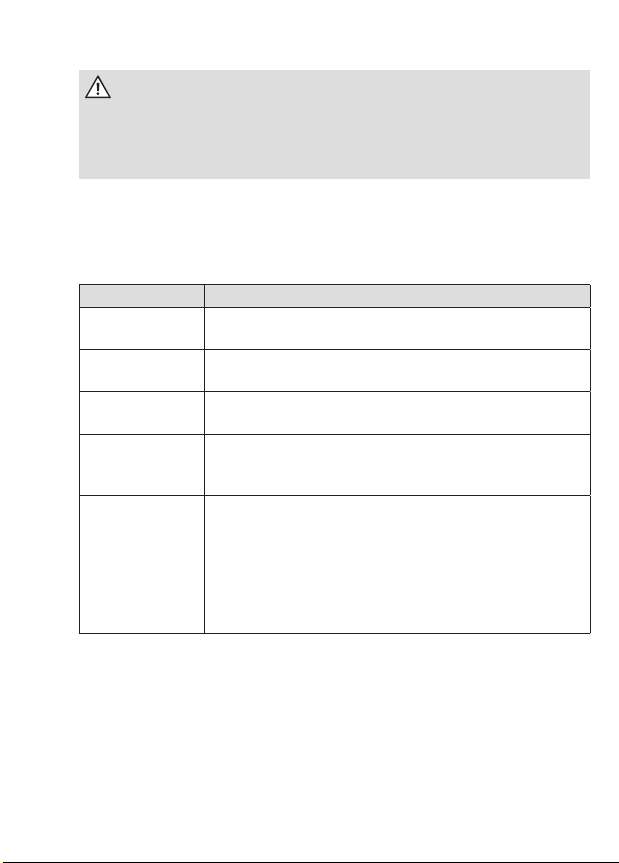
The following table names the components and how they are to be
treated at the end of their life cycle.
Components Waste collection and disposal
Printed circuit
boards
Electronic waste: Dispose of such waste in accord-
ance with the local regulations.
LEDs, LC
displays
Hazardous waste: Dispose of such waste in accord-
ance with the local regulations.
Metal parts Recyclable material: Sort such material and send it
for recycling.
Plastic parts Send sorted plastic parts to a recycling plant (re-
granulation) or, where applicable, to a waste inciner-
ation plant (thermal energy generation).
Batteries Take safety precautions against short circuits before
disposing of the batteries. Batteries can leak or
self-ignite. Dispose of the batteries in their original
packaging or insulate the terminals. Do not dispose
of batteries with the domestic waste. Instead, observe
the locally applicable waste and environmental
protection standards.
Basic safety instructions
Please adhere to the following basic safety instructions:
yRead all the enclosed instructions and information.
yObserve the warnings on the device and in the documents.

5
yAlways be aware of safety issues and hazards when working on
the device.
yThe applicable occupational health and safety regulations for electri-
cal installations must be observed during assembly, installation and
removal of the device.
yMake sure that the installation and operating location of the device
yBefore assembly, check the devices for any externally visible damage.
y
line with its intended use.
yThe connection cables used to connect a meter must be selected to
match the maximum load of the meter and the installation environ-
ment in terms of type, cross section, voltage and temperature.
y
yObserve the maintenance and warranty instructions.
yIf the mains power fails and then returns, there is no need to do
anything to the meter.
Notes on correctness of measurements
For the notes on correctness of measurements applicable to
this meter in Germany, please see the enclosed document enti-
tled “Notes on correctness of measurements for LZQJ-SGM.”
Technical data
Voltage, current,
frequency, utilisation
category
See name plate
Overvoltage category
Rated peak withstand
voltage
OVC III (as per EN 62052-31)
4 kV (as per EN 62052-31)
Input
System voltage
100...240 V

6
Data interfaces
Optical
Electrical
Optical data interface D0 (38400 baud),
as per EN 62056-21
RS232 (115200 baud), as per
ANSI EIA/TIA-232-F (R1997)
RS485 (115200 baud), as per
ANSI/TIA/EIA-485-A-98 (R2003)
CL0 (19200 baud), as per DIN 66348-1
Output
Optocoupler MOSFET
max. 250 V AC/DC, max. 100 mA
Power consumption per
phase as per EN 62053-61
Base meter
Voltage circuit
Current path
Multifunction mode
approx. 95% power
consumption in
voltage circuit as per
EN 62052-31
<1.2 W / <1.9 VA
<0.04 VA
max. 2.1 W / 2.7 VA @ 3 x 58/100 V AC (RMS)
max. 2.4 W / 4.0 VA @ 3 x 240/415 V AC (RMS)
Temperature range −25 °C...+55 °C
Limit range for operation, storage and transport:
−40 °C...+70 °C
Altitude Operation up to 3,000 m
Humidity Maximum 95%, non-condensing, as per
EN 62052-11, EN 50470-1 and EN 60068-2-30
Protection class II
Degree of protection IP 54
Fire properties As per EN 62052-31
Environmental conditions Mechanical:
M1 according to the Measuring Instruments Directive
(2014/32/EU)
Electromagnetic:
E2 according to the Measuring Instruments Directive
(2014/32/EU)
Intended operating location:
Interior as per EN 50470-1
Weight Approx. 1.0 kg (transformer connected meter)

7
Housing, display and control elements
1 - Name plate
2 - Test LED for reactive power
3 - LC display
4 - Test LED for active power
5 - Optical call sensor (optional)
6 - Meter cover
7 - Sealing screw
8 - Optical data interface D0
9 - Call-up button
10 - Transformer plate (only for transformer connected meters)
11 - Reset button
12 -
13 - Module compartment
14 - Terminal cover
15 - Sealing screws

8
Optical call sensor: Used to call up the display lists on the
display. The sensor is operated with a
focussing torch.
Optical data
interface D0:
For communication between meter and
read-out device by means of an optical
more information on the optical data inter-
face in the user manual.
Module compartment:
A modem or interface module can be
installed here. Installation and removal
can be performed under voltage.

9
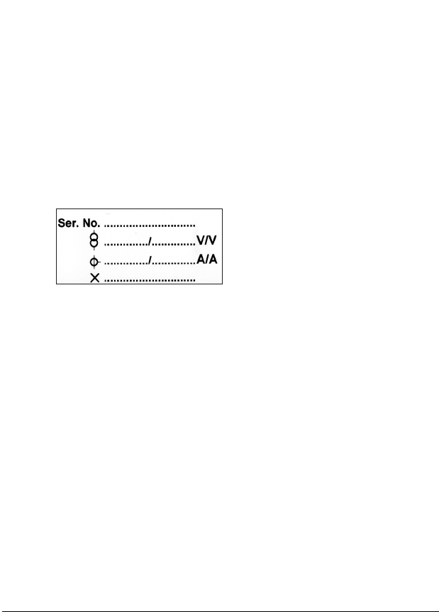
Name plate (example)
1 - Year of construction
2 - Test LED for reactive power
3 - Serial number
4 - Test LED for active power
5 - Product standard
6 - Optical call sensor
7 - Overvoltage category
8 - Accuracy class
9 - Operating temperature
10 - Space for ownership labelling
11 - Information about connection of the meter
12 - OBIS codes for the most important registers
13 -
14 - Safety and application information
15 - Voltage, current, frequency
16 - Type designation and type code
10
-
The cursor labelling below the display and the description of the OBIS
code numbers on the name plate are designed as standard and not
adapted to the meter version.
in question.
Transformer plate
Transformer connected meters (usually secondary meters) are
equipped with a transformer plate. It is located under the sealable
11
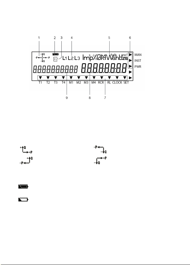
LC display
The LZQJ-SGM is equipped with a liquid crystal (LC) display as per
1. The operation display shows the energy direction that is currently
being measured by the meter (supply/draw of active power, inductive/
direction arrow indicates which quadrant is being used for the
measurement, e.g.:
1st quadrant +P/+Q 3rd quadrant −P/−Q
2nd quadrant −P/+Q 4th quadrant +P/−Q
2. The battery status indicator shows the residual capacity of
the internal power reserve of the real time clock.
= Power reserve run-down, internal battery is empty or not
available. In this instance, the real time clock cannot be
3. The communication display lights up permanently when the data
interface (optical or electrical) and the meter are communicating.
4. The phase display indicates when individual phase voltages are

12
5. The unit shown matches the type of energy being measured or the
measured value displayed.
6. The additional cursor eld displays the operating states for the
meter. The arrows indicate whether any manipulation or an installation
error was registered or if the power threshold was exceeded.
MAN The cursor is active where any manipulation of the terminal
INST The cursor is active if an entry has been registered in the
installation control register.
PWR
meter was exceeded.
7. The standard cursor eld displays the operating states for the
internal device clock.
T1 - T4
M1 - M4
RL
is active.
CLOCK The cursor is active when the internal device clock actu-
SET The corresponding cursor is active when the meter is in
the Set mode.
8. The value area displays the measured values.
9. The code area
the OBIS key. The display can show all six value groups.

13
Installation and start-up
The meters in series LZQJ-SGM
are suitable for wall mounting as per
DIN 43857-2.
When connecting the meter, always
observe the corresponding connec-
tion diagram, which is located on the
meter’s name plate and in the delivery
documents. Please also observe
the notes on the installation control
register.
DANGER
Risk of fatal injury due to arcing and electric shock!
The voltage taps in the meter are not fuse-protected, and are connect-
ed directly to the measuring voltage potential.
yExternal devices that are operated using the meter’s voltage taps
the applicable technical regulations.
yThe transformer connected meter must be fuse-protected in a voltage
DANGER
Risk of fatal injury due to arcing and electric shock!
The inputs and outputs for the additional terminals are not fuse-pro-
tected in the meter.
y
the applicable technical regulations.
y-
tions on the meter name plate in accordance with the applicable
technical regulations.
y

14
DANGER
Risk of fatal injury in case of contact with live parts!
During installation or when replacing the meter, the wires connected to
the meter must be de-energised.
yThe installer bears responsibility for coordinating the rated values
and parameters of the supply-side overcurrent protection devices
with the maximum rated currents of the meter.
yRemove the corresponding pre-fuses, on the mains side and on the
creation side in case of a two-sided feed. Store them in a secure
location to ensure that no one else can insert the pre-fuses again
without being noticed.
yIf you use selective automatic circuit breakers for system discon-
nection, secure them to prevent them from being switched on again
without being noticed.
yBefore the installation of a meter, make sure that the consequences
of disconnecting the electrical system will not result in immediate
danger to the life or health of persons or cause any economic
damage.
yTo avoid any immediate hazards or damage, take appropriate
measures to prevent malfunctions before disconnection of the
system.
y
connection of the meter.
ATTENTION
Application of excessive torque will damage the connection
terminals!
The appropriate torque is dependent on the type of connection line
involved and its maximum current.
yTighten the connection terminals to the corresponding torque as
per EN 60999-1.
15
Transformer
connected meter
Current and voltage
terminals
Additional
terminals
Terminal dimensions
W x H or d (mm) 5.3 x 5.5 2.6 x 2.2
Minimum connection cross
sections (mm²) 2.5 1.0
Maximum connection
cross sections (mm²)* 10 2.5
Minimum torques
(Nm) 1.2 —
Maximum torques
(Nm) 1.7 —
Screw type
Cross slot combination screw
type PZ1
(as per ISO 4757)
Spring-loaded
terminal
Thread size M4 —
Stripping length (mm) 10.0 5.0
* Rated connection capacity based on EN 60999-1
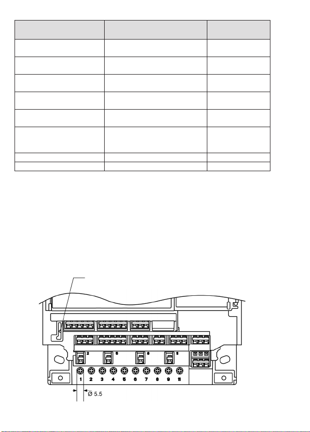
Terminal block
the meter.
View from the front (maximum terminal assignment,
specications in mm)
Button for manipulation recognition
of the terminal cover

16
View from below (maximum terminal assignment,
specications in mm)
DANGER
Risk of fatal injury from high voltage when power transformers
disconnected!
In transformer connected meters, the high voltage generated on
a disconnected power transformer can cause fatal injuries and result
in electric arcs on the terminal block.
yBefore disconnecting the current paths, short-circuit the secondary
circuits of the power transformer at its testing terminals.
DANGER
Danger to life due to excess voltages on the terminals of the
current paths!
The voltages on the terminals of the current paths must not be higher
than the rated voltages of the voltage circuits and not be higher than
yUse the meter only with suitable current transformers to avoid
exceeding the voltage limits. If necessary, the secondary side of
the transformers must be earthed.

17
DANGER
Risk of fatal injury from high voltage when voltage transformers
are used!
yObserve all the safety instructions in the documents for the voltage
transformers in use.
yIf necessary, the secondary side of the voltage transformers must
be earthed.
Connection to current and voltage terminals
Proceed as follows when connecting the LZQJ-SGM:
1. Ensure that all lines are free from voltage.
2. Shorten the conductors to the necessary length if necessary.
3. Strip 9 to 10 mm of each conductor.
4.
a ferrule.
5. Open the screw-type terminal.
6. Insert the conductor into the screw-type terminal up to its
insulation.
7. Tighten the screw of the screw-type terminal while observing
the cable insulation is not put inside the terminal.
8. Repeat the process until all conductors are connected.
Connection to spring-loaded terminals
Proceed as follows to connect external devices to the spring-loaded
terminals:
1. Shorten the conductors to the necessary length.
2. Strip 4 to 5 mm of the conductor.
3.
that all individual wires are fully inside the terminal.

18
4. Push the lever of the spring-loaded terminal
down with the screwdriver until the terminal
opens.
5. Insert the line into the open terminal up to its
insulation. Ensure that the cable insulation is
not put inside the terminal.
6. Remove the screwdriver to allow the
terminal to close.
7. Repeat the process until all conductors are connected.
Information on connecting interfaces
Example:

19
the user manual.
In addition to the connection diagram for current and voltage, the type
plate contains information on the interfaces, such as the maximum
voltage of the outputs, for example.
The interfaces are marked with numbers, which can be found above the
matching terminals in the terminal block area. Framed terminal numbers
indicate the respective earth (GND) of the interface.
The electrical data interfaces RS232, RS485 and CL0 are implemented
by means of spring-loaded terminals.
The assignment is as follows:
RS232
Tx Rx RS GND
23 24 27
RS485
A(-) B(+) RS GND
23 24 27
CL0
+NC -
23 24
Securing the terminal cover
To prevent any unauthorised access to the connection terminals, the
terminal cover is attached with 2 sealing screws (slot and PZ2 drive),
which you can secure with seals.

20
ATTENTION
Application of excessive torque will damage the device!
yTighten the sealing screws on the terminal cover with a maximum
torque of 0.5 Nm.
Functions and operation
For a detailed description on operating the LZQJ-SGM by means of a
PC connected to the meter, please see the chapter on the COMBI-
MASTER 2.0 in the user manual. The following sections describe only
the procedure using the buttons on the device itself.
Calling up display lists
The display lists below can be displayed on the meter display. The dis-
play is operated by means of the call-up and reset button. As an alterna-
tive to the call-up button, it is possible to use the optical call sensor.
The display lists contain the following:
yOperation display (alternating display)
yDisplay test
yCall list (Std-dAtA display all register contents in the list)
yP.01
yAdjustment list (SEt edit adjustable variables)
yInformation list (InFO-dAtA display instantaneous values)
MASTER 2.0 tool.
Other manuals for LZQJ-SGM
1
Table of contents
Other EMH metering Measuring Instrument manuals


 Beta Module user guide")


