manuals.online logo
Brands
  1. Home
  2. •
  3. Brands
  4. •
  5. Chauvin Arnoux
  6. •
  7. Measuring Instrument
  8. •
  9. Chauvin Arnoux AEMC MN352 User manual

Chauvin Arnoux AEMC MN352 User manual

99-MAN 100160.v9 04/15
OPERATION
Please make sure that you have already read and fully understand the WARNING section on page 1.
Making Measurements with the AC Current Probe Model MN352/MN353
Connect the black lead of the current probe to “common” and the red lead to the AC voltage input on
your DMM or other voltage-measuring instrument. The AC current probe has an output of 10mV/A. This
means that for 200AAC in a conductor around which the probe is clamped, 2VAC will come out of the
probe leads to your DMM or instrument. Select the range which corresponds to the measured current.
If the current magnitude is unknown, start with the highest range and work down until the appropriate
range and resolution are reached. Clamp the probe around the conductor. Take the reading on the
meter and multiply it by 100 to obtain the measured current (e.g, 160mV reading = 160 x 100 =
16,000mA or 16A)
For best accuracy, avoid if possible, the proximity of other conductors which may create noise.
Tips for Making Precise Measurements
When using a current probe with a meter, it is important to select the range that provides the best
resolution. Failure to do this may result in measurement errors.
Make sure that probe jaw mating surfaces are free of dust and contamination. Contaminants cause air
gaps between the jaws, increasing the phase shift between primary and secondary. It is very critical for
power measurement.
MAINTENANCE:
Warning
For maintenance use only original factory replacement parts.
To avoid electrical shock, do not attempt to perform any servicing unless you are qualified to do so.
To avoid electrical shock and/or damage to the instrument, do not get water or other foreign agents
into the probe.
Cleaning:
To ensure optimum performance, it is important to keep the probe jaw mating surfaces clean at all times.
Failure to do so may result in error in readings. To clean the probe jaws, use very fine sand paper (fine
600) to avoid scratching the jaw, then gently clean with a soft oiled cloth.
REPAIR AND CALIBRATION
You must contact our Service Center for a Customer Service Authorization number (CSA#). This will
ensure that when your instrument arrives, it will be tracked and processed promptly. Please write the CSA#
on the outside of the shipping container.
Chauvin Arnoux®, Inc. d.b.a. AEMC®Instruments
15 Faraday Drive Dover, NH 03820 USA
(800) 945-2362 (Ext. 360) • (603) 749-6434 (Ext. 360) • [email protected]
(Or contact your authorized distributor)
NOTE: All customers must obtain a CSA# before returning any instrument.
TECHNICAL AND SALES ASSISTANCE
If you are experiencing any technical problems, or require any assistance with the proper use or
application of this instrument, please contact our technical hotline:
(800) 343-1391 • (508) 698-2115 • [email protected]
LIMITED WARRANTY
The current probe is warranted to the owner for a period of one year from the date of original purchase
against defects in manufacture. This limited warranty is given by AEMC®Instruments, not by the
distributor from whom it was purchased. This warranty is void if the unit has been tampered with, abused
or if the defect is related to service not performed by AEMC®Instruments.
Full warranty coverage and product registration is available on our website at:
www.aemc.com/warranty.html.
Please print the online Warranty Coverage Information for your records.
AC Current Probe
Models MN352 and MN353
User Manual
DESCRIPTION
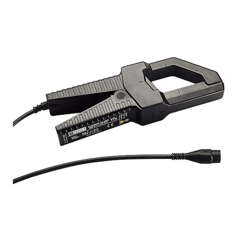
The MN352/353 (Catalog #2116.26 and #2116.27) are the latest in compact AC current probes.
Designed to meet the most stringent demands in industry and electrical contracting, they also meet the
latest safety and performance standards. The probes have a measurement range up to 240 Arms which
make them perfect tools for measurements with DMMs, recorders, power and harmonic meters. The
Models MN352/MN353 are compatible with any AC voltmeter, multimeter, or other voltage
measurement instrument that is capable of displaying 10mV of output per amp of measured current, an
accuracy of 0.75% or better and an input impedance of 1 M.
WARNING
The safety warnings are provided to ensure the safety of personnel and proper operation of the
instrument. Read the instruction completely.
• Use caution on any circuit: potentially high voltages and currents may be present and may pose
a shock hazard.
• Do not use the probe if damaged. Always connect the current probe to the measuring device
before it is connected around the conductor
• Do not use on non-insulated conductor with a potential to ground greater than 600V CAT III
pollution 2. Use extreme caution when clamping around bare conductors or bus bars.
• Before each use, inspect the probe; look for cracks in housing or output cable insulation.
• Do not use clamp in wet environment or in locations that hazardous gases exist.
• Do not use the probe anywhere beyond the tactile barrier.
INTERNATIONAL ELECTRICAL SYMBOLS
This symbol signifies that the current probe is protected by double or reinforced insulation. Use
only factory specified replacement parts when servicing the instrument.
This symbol signifies CAUTION! and requests that the user refer to the user manual before
using the instrument.
This is a type A current sensor. This symbol signifies that application around and removal from
HAZARDOUS LIVE conductors is permitted.
DEFINITION OF MEASUREMENT CATEGORIES
CAT IV: For measurements performed at the primary electrical supply (<1000V) such as on primary
overcurrent protection devices, ripple control units, or meters.
CAT III: For measurements performed in the building installation at the distribution level such as on
hardwired equipment in fixed installation and circuit breakers.
CAT II: For measurements performed on circuits directly connected to the electrical distribution system.
Examples are measurements on household appliances or portable tools.
RECEIVING YOUR SHIPMENT
Upon receiving your shipment, make sure that the contents are consistent with the packing list. Notify
your distributor of any missing items. If the equipment appears to be damaged, file a claim immediately
with the carrier and notify your distributor at once, giving a detailed description of any damage.
ELECTRICAL SPECIFICATIONS
Nominal Range: 150A
Measurement Range: 0.1 to 200A
Transformation Ratio: Voltage output
Output Signal: 10mV/A
Accuracy and Phase Shift*:
Accuracy:
0.1 to 1A: 3% Reading ± 200µV
1 to 20A: 2% Reading ± 200µV
20 to 80A: 1% Reading
80 to 150A: 3% Reading
150 to 200A: 7% Reading
Phase Shift:
0.1 to 1A: Not Specified
1 to 20A: 3°
20 to 80A: 2°
80 to 150A: 3°
150 to 200A: 4°
(*Reference conditions: 18°C to 28°C, 20 to 75%
RH, external magnetic field <40 A/m, 48 to 65 Hz
sine wave, distortion factor less than 1%, no DC
component, no external current carrying conductor,
test sample centered.)
Load impedance > 1 M.
Frequency Range: 40 to 10kHz
Limit Operating Conditions:
200A permanently to 1kHz;
Derating above 3kHz: 200A x (1/0.333F), F in kHz
Crest Factor:
3 @ 150A peak max with an error
(due to CF) of 3%
Overload: 240A for 10 min ON, 30 min OFF
Working Voltage: 600Vrms
Common Mode Voltage: 600Vrms
Influence of Adjacent Conductor:
< 15mA/A at 50 Hz
Influence of DC on AC signal:
DC Current < 10A, < 10%
Influence of Conductor Position in Jaw:
0.5% of mV output @ 50/60 Hz
Influence of Frequency:
40 Hz to 1 kHz: 5% of mV output
1 kHz to 10 kHz:15% of mV output
Influence of Load:
< 3% of mA output from 40 Hz to 1 kHz
< 12% of mA output from 1 kHz to 10 kHz
Influence of Temperature:
200 ppm/°K, or 0.2% of mV output per 10°K
Influence of Humidity (10 - 90% RH):
0.2% of mV output per 10°K @ 18°C to 28°C
MECHANICAL SPECIFICATIONS
Operating Temperature:
14° to 131°F (-10° to +55°C)
Storage Temperature:
-40° to 158°F (-40° to +70°C)
Operating Relative Humidity:
10-35°C 85% RH
(without roll-off above 35°C)
Maximum Cable Diameter:
One Ø 0.78” (20mm), bus bar 20 x 5mm
Case Protection:
IP 40 (IEC 529)
Drop Test:
Test per IEC 68-2-32:
1.0m drop on 38 mm of Oak on concrete.
Mechanical Shock:
Test per IEC 68-2-27
Vibration:
Test per IEC 68-2-6
Dimensions:
5.47 x 2.00 x 1.18" (139 x 51 x 30mm)
Weight:
180 g (6.5 oz)
Polycarbonate Material:
Jaws: Polycarbonate with 10% fiberglass charge,
Red UL 94 V0
Case: Polycarbonate 920A Gray
Opening Operations - Life:
> 50,000
Output:
MN352: Two standard safety banana jacks (4mm)
MN353: Double/reinforced insulated 5 ft (1.5m)
lead with safety 4mm banana plug
SAFETY SPECIFICATIONS
Electrical:
Double insulation or reinforced insulation between
the primary or secondary and the outer case of
the handle conforms to IEC 1010-2-32.
Common Mode Voltage:
600V Category III
Pollution Degree 2
Dielectric Strength:
5550 V, 50/60 Hz between primary, secondary
and the outer case of the handle
Electromagnetic Compatibility:
EN 50081-1 Class B
EN 50082-2 Electrostatic discharge
IEC 1000-4-2
Radiated field IEC 1000-4-3
Fast transients IEC 1000-4-4
Magnetic field at 50/60 Hz IEC 1000-4-8
ORDERING INFORMATION
AC Current Probe MN352 ..........Cat #2116.26
AC Current Probe MN353 ..........Cat #2116.27
Accessories:
Leads, set of 2, 5 ft safety
(1000V) for Model MN352............Cat #2111.29
Banana plug adapter
(to non-recessed plug) ................Cat #1017.45
E192383
2.56"
(65 mm)
5.47"
(139 mm)
.83"
(21 mm)
Black
Red
.73"
2.00"
(51 mm)
(18.5 mm)
1.18"
(30 mm)
Tactical
Barrier
(keep hands below
this barrier)
ELECTRICAL SPECIFICATIONS
Nominal Range: 150A
Measurement Range: 0.1 to 150A
Transformation Ratio: Voltage output
Output Signal: 10mV/A
Accuracy and Phase Shift*:
Accuracy:
0.1 to 1A: 3% Reading ± 200µV
1 to 20A: 2% Reading ± 200µV
20 to 80A: 1% Reading
80 to 150A: 3% Reading
150 to 200A: 7% Reading
Phase Shift:
0.1 to 1A: Not Specified
1 to 20A: 3°
20 to 80A: 2°
80 to 150A: 3°
150 to 200A: 4°
(*Reference conditions: 18°C to 28°C, 20 to 75%
RH, external magnetic field <40 A/m, 48 to 65 Hz
sine wave, distortion factor less than 1%, no DC
component, no external current carrying conductor,
test sample centered.)
Load impedance > 1 M.
Frequency Range: 40 to 10kHz
Limit Operating Conditions:
200A permanently to 1kHz;
Derating above 3kHz: 200A x (1/0.333F), F in kHz
Crest Factor:
3 @ 150A peak max with an error
(due to CF) of 3%
Overload: 240A for 10 min ON, 30 min OFF
Working Voltage: 600Vrms
Common Mode Voltage: 600Vrms
Influence of Adjacent Conductor:
< 15mA/A at 50 Hz
Influence of DC on AC signal:
DC Current < 10A, < 10%
Influence of Conductor Position in Jaw:
0.5% of mV output @ 50/60 Hz
Influence of Frequency:
40 Hz to 1 kHz: 5% of mV output
1 kHz to 10 kHz:15% of mV output
Influence of Load:
< 3% of mA output from 40 Hz to 1 kHz
< 12% of mA output from 1 kHz to 10 kHz
Influence of Temperature:
200 ppm/°K, or 0.2% of mV output per 10°K
Influence of Humidity (10 - 90% RH):
0.2% of mV output per 10°K @ 18°C to 28°C
MECHANICAL SPECIFICATIONS
Operating Temperature:
14° to 131°F (-10° to +55°C)
Storage Temperature:
-40° to 158°F (-40° to +70°C)
Operating Relative Humidity:
10-35°C 85% RH
(without roll-off above 35°C)
Maximum Cable Diameter:
One Ø 0.78” (20mm), bus bar 20 x 5mm
Case Protection:
IP 40 (IEC 529)
Drop Test:
Test per IEC 68-2-32:
1.0m drop on 38 mm of Oak on concrete.
Mechanical Shock:
Test per IEC 68-2-27
Vibration:
Test per IEC 68-2-6
Dimensions:
5.47 x 2.00 x 1.18" (139 x 51 x 30mm)
Weight:
180 g (6.5 oz)
Polycarbonate Material:
Jaws: Polycarbonate with 10% fiberglass charge,
Red UL 94 V0
Case: Polycarbonate 920A Gray
Opening Operations - Life:
> 50,000
Output:
MN352: Two standard safety banana jacks (4mm)
MN353: Double/reinforced insulated 5 ft (1.5m)
lead with safety 4mm banana plug
SAFETY SPECIFICATIONS
AC Current Probe MN352 ..........Cat #2116.26
AC Current Probe MN353 ..........Cat #2116.27
Accessories:
Leads, set of 2, 5 ft safety
(1000V) for Model MN352............Cat #2111.29
Banana plug adapter
(to non-recessed plug) ................Cat #1017.45
E192383
Electrical:
Double insulation or reinforced insulation between
the primary or secondary and the outer case of
the handle conforms to IEC 1010-2-32.
Common Mode Voltage:
600V Category III
Pollution Degree 2
Electromagnetic Compatibility:
Emission and immunity in an industrial
environment according to EN61326-1
ORDERING INFORMATION
2.56"
(65 mm)
5.47"
(139 mm)
.83"
(21 mm)
Black
Red
.73"
2.00"
(51 mm)
(18.5 mm)
.1.18"
(30 mm)
Tactical
Barrier
(keep hands below
this barrier)
99-MAN 100160 v11 05/19
OPERATION
Please make sure that you have already read and fully understand the WARNING section on page 1.
Making Measurements with the AC Current Probe Model MN352/MN353
Connect the black lead of the current probe to “common” and the red lead to the AC voltage input on
your DMM or other voltage-measuring instrument. The AC current probe has an output of 10mV/A. This
means that for 200AAC in a conductor around which the probe is clamped, 2VAC will come out of the
probe leads to your DMM or instrument. Select the range which corresponds to the measured current.
If the current magnitude is unknown, start with the highest range and work down until the appropriate
range and resolution are reached. Clamp the probe around the conductor. Take the reading on the
meter and multiply it by 100 to obtain the measured current (e.g, 160mV reading = 160 x 100
= 16,000mA or 16A).
For best accuracy, avoid if possible, the proximity of other conductors which may create noise.
Tips for Making Precise Measurements
When using a current probe with a meter, it is important to select the range that provides the best
resolution. Failure to do this may result in measurement errors.
Make sure that probe jaw mating surfaces are free of dust and contamination. Contaminants cause air
gaps between the jaws, increasing the phase shift between primary and secondary. It is very critical for
power measurement.
MAINTENANCE:
Warning
For maintenance use only original factory replacement parts.
To avoid electrical shock, do not attempt to perform any servicing unless you are qualified to do so.
To avoid electrical shock and/or damage to the instrument, do not get water or other foreign agents
into the probe.
Cleaning:
To ensure optimum performance, it is important to keep the probe jaw mating surfaces clean at all times.
Failure to do so may result in error in readings. To clean the probe jaws, use very fine sand paper (fine
600) to avoid scratching the jaw, then gently clean with a soft oiled cloth.
REPAIR AND CALIBRATION
You must contact our Service Center for a Customer Service Authorization number (CSA#). This will
ensure that when your instrument arrives, it will be tracked and processed promptly. Please write the CSA#
on the outside of the shipping container.
Chauvin Arnoux®, Inc. d.b.a. AEMC®Instruments
15 Faraday Drive Dover, NH 03820 USA
(800) 945-2362 (Ext. 360) • (603) 749-6434 (Ext. 360) • [email protected]
(Or contact your authorized distributor)
NOTE: All customers must obtain a CSA# before returning any instrument.
TECHNICAL AND SALES ASSISTANCE
If you are experiencing any technical problems, or require any assistance with the proper use or
application of this instrument, please contact our technical hotline:
(800) 343-1391 • (508) 698-2115 • [email protected]
LIMITED WARRANTY
The current probe is warranted to the owner for a period of two years from the date of original purchase
against defects in manufacture. This limited warranty is given by AEMC®Instruments, not by the
distributor from whom it was purchased. This warranty is void if the unit has been tampered with, abused
or if the defect is related to service not performed by AEMC®Instruments.
Full warranty coverage and product registration is available on our website at:
www.aemc.com/warranty.html.
Please print the online Warranty Coverage Information for your records.
AC Current Probe
Models MN352 and MN353
User Manual
DESCRIPTION
The MN352/353 (Catalog #2116.26 and #2116.27) are the latest in compact AC current probes.
Designed to meet the most stringent demands in industry and electrical contracting, they also meet the
latest safety and performance standards. The probes have a measurement range up to 240 Arms which
make them perfect tools for measurements with DMMs, recorders, power and harmonic meters. The
Models MN352/MN353 are compatible with any AC voltmeter, multimeter, or other voltage
measurement instrument that is capable of displaying 10mV of output per amp of measured current, an
accuracy of 0.75% or better and an input impedance of 1 M.
WARNING
The safety warnings are provided to ensure the safety of personnel and proper operation of the
instrument. Read the instruction completely.
• Use caution on any circuit: potentially high voltages and currents may be present and may pose
a shock hazard.
• Do not use the probe if damaged. Always connect the current probe to the measuring device
before it is connected around the conductor
• Do not use on non-insulated conductor with a potential to ground greater than 600V CAT III
pollution 2. Use extreme caution when clamping around bare conductors or bus bars.
• Before each use, inspect the probe; look for cracks in housing or output cable insulation.
• Do not use clamp in wet environment or in locations that hazardous gases exist.
• Do not use the probe anywhere beyond the tactile barrier.
INTERNATIONAL ELECTRICAL SYMBOLS
This symbol signifies that the current probe is protected by double or reinforced insulation. Use
only factory specified replacement parts when servicing the instrument.
This symbol signifies CAUTION! and requests that the user refer to the user manual before
using the instrument.
This is a type A current sensor. This symbol signifies that application around and removal from
HAZARDOUS LIVE conductors is permitted.
DEFINITION OF MEASUREMENT CATEGORIES
CAT II: For measurements performed on circuits directly connected to the electrical distribution system.
Examples are measurements on household appliances or portable tools.
CAT III: For measurements performed in the building installation at the distribution level such as on
hardwired equipment in fixed installation and circuit breakers.
CAT IV: For measurements performed at the primary electrical supply (<1000V) such as on primary
overcurrent protection devices, ripple control units, or meters.
RECEIVING YOUR SHIPMENT
Upon receiving your shipment, make sure that the contents are consistent with the packing list. Notify
your distributor of any missing items. If the equipment appears to be damaged, file a claim immediately
with the carrier and notify your distributor at once, giving a detailed description of any damage.

This manual suits for next models

5

Other Chauvin Arnoux Measuring Instrument manuals

Chauvin Arnoux CA 6161 User manual

Chauvin Arnoux

Chauvin Arnoux CA 6161 User manual

Chauvin Arnoux C.A762 User manual

Chauvin Arnoux

Chauvin Arnoux C.A762 User manual

Chauvin Arnoux PSD 1 User manual

Chauvin Arnoux

Chauvin Arnoux PSD 1 User manual

Chauvin Arnoux E1N User manual

Chauvin Arnoux

Chauvin Arnoux E1N User manual

Chauvin Arnoux MEMO MD65 User manual

Chauvin Arnoux

Chauvin Arnoux MEMO MD65 User manual

Chauvin Arnoux C.A 1623 User manual

Chauvin Arnoux

Chauvin Arnoux C.A 1623 User manual

Chauvin Arnoux C.A 6255 User manual

Chauvin Arnoux

Chauvin Arnoux C.A 6255 User manual

Chauvin Arnoux CA834 User manual

Chauvin Arnoux

Chauvin Arnoux CA834 User manual

Chauvin Arnoux C.A 6513 User manual

Chauvin Arnoux

Chauvin Arnoux C.A 6513 User manual

Chauvin Arnoux AEMC Simple Logger SL Series Service manual

Chauvin Arnoux

Chauvin Arnoux AEMC Simple Logger SL Series Service manual

Chauvin Arnoux AEMC Instruments OX5042 User manual

Chauvin Arnoux

Chauvin Arnoux AEMC Instruments OX5042 User manual

Chauvin Arnoux 6250 User manual

Chauvin Arnoux

Chauvin Arnoux 6250 User manual

Chauvin Arnoux C.A 811 User manual

Chauvin Arnoux

Chauvin Arnoux C.A 811 User manual

Chauvin Arnoux pel 102 User manual

Chauvin Arnoux

Chauvin Arnoux pel 102 User manual

Chauvin Arnoux MiniFLEX  MA200 User manual

Chauvin Arnoux

Chauvin Arnoux MiniFLEX MA200 User manual

Chauvin Arnoux Enerdis mDIGI2-P User manual

Chauvin Arnoux

Chauvin Arnoux Enerdis mDIGI2-P User manual

Chauvin Arnoux C.A 1550 User manual

Chauvin Arnoux

Chauvin Arnoux C.A 1550 User manual

Chauvin Arnoux F 65 User manual

Chauvin Arnoux

Chauvin Arnoux F 65 User manual

Chauvin Arnoux C.A 6608 User manual

Chauvin Arnoux

Chauvin Arnoux C.A 6608 User manual

Chauvin Arnoux C.A 1227 User manual

Chauvin Arnoux

Chauvin Arnoux C.A 1227 User manual

Chauvin Arnoux C.A 6545 User manual

Chauvin Arnoux

Chauvin Arnoux C.A 6545 User manual

Chauvin Arnoux MEMO MD65 User manual

Chauvin Arnoux

Chauvin Arnoux MEMO MD65 User manual

Chauvin Arnoux CA 10 User manual

Chauvin Arnoux

Chauvin Arnoux CA 10 User manual

Chauvin Arnoux C.A 6545 User manual

Chauvin Arnoux

Chauvin Arnoux C.A 6545 User manual

Popular Measuring Instrument manuals by other brands

PASCO PS-3515 instruction sheet

PASCO

PASCO PS-3515 instruction sheet

Burster RESISTOMAT 2329 Operation manual

Burster

Burster RESISTOMAT 2329 Operation manual

SARAD Radon Scout Home manual

SARAD

SARAD Radon Scout Home manual

Blue-White industries F-462 Series instruction manual

Blue-White industries

Blue-White industries F-462 Series instruction manual

Fluke 1653B manual

Fluke

Fluke 1653B manual

Zamel EXTA LDM-10 instruction manual

Zamel

Zamel EXTA LDM-10 instruction manual

ACO 6236 instruction manual

ACO

ACO 6236 instruction manual

Kusam-meco KM 1002 user manual

Kusam-meco

Kusam-meco KM 1002 user manual

HEDÜ Laser plumb Bob II manual

HEDÜ

HEDÜ Laser plumb Bob II manual

Eno Scientific Well Watch 670 user manual

Eno Scientific

Eno Scientific Well Watch 670 user manual

AmScope HL250-A Series user manual

AmScope

AmScope HL250-A Series user manual

PCB Piezotronics IMI SENSORS 683A1 Installation and operating manual

PCB Piezotronics

PCB Piezotronics IMI SENSORS 683A1 Installation and operating manual

SEFRAM MW 3517BF user manual

SEFRAM

SEFRAM MW 3517BF user manual

Banner Q5X quick start guide

Banner

Banner Q5X quick start guide

Sthor 81716 manual

Sthor

Sthor 81716 manual

CyberVisuell LDW-6095K Operation manual

CyberVisuell

CyberVisuell LDW-6095K Operation manual

Vetland V1407 user manual

Vetland

Vetland V1407 user manual

ESD SYSTEMS SPI Westek 95420 Operation and maintenance manual

ESD SYSTEMS

ESD SYSTEMS SPI Westek 95420 Operation and maintenance manual

manuals.online logo
manuals.online logoBrands
  • About & Mission
  • Contact us
  • Privacy Policy
  • Terms and Conditions

Copyright 2025 Manuals.Online. All Rights Reserved.