EMH metering DIZ User manual

Scope of delivery.................................................................................... 2
Important information.............................................................................. 2
General description ................................................................................ 5
Technical data......................................................................................... 5
Housing, display and control elements................................................... 7
Interfaces.............................................................................................. 12
Inputs and outputs................................................................................ 14
Installation and start-up ........................................................................ 17
Meter operation .................................................................................... 26
Abbreviations........................................................................................ 46
EU Declaration of Conformity............................................................... 47
Instructions for use
EN
DIZ-G-EMH-BIA-E-1.60
DIZ Generation G
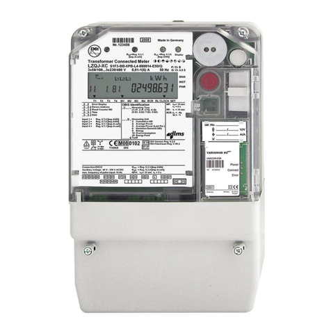
Digital industrial meter
Issue date: 15 February 2022; subject to technical changes!
Specications apply under reference conditions.
EMH metering
GmbH & Co. KG
Neu-Galliner Weg 1 • 19258 Gallin
GERMANY
Tel. +49 38851 326-0
Fax +49 38851 326-1129
Web www.emh-metering.com
Tel. +49 38851 326-1930 (Technical Support)
Email [email protected]

2
Scope of delivery
Please check that the contents of the packing box are complete before
starting the installation and start-up procedure.
y1 Generation G DIZ device
y1 Instructions for use
yAccessory (optional):
• Path separator
If the contents are incomplete or damaged, please contact your supplier.
Store, use and transport the device in such a way that it is protected
against moisture, dirt and damage.
Important information
These instructions for use are part of the documentation.
These instructions list all the dierent device versions. Some of the fea-
tures described herein may not be applicable to your particular device.
Please see the product manual for more comprehensive
information about the device. Please also observe all the docu-
ments included with other components.
Target audience
These instructions are intended for technicians who are responsible for
the installation, connection and servicing of the devices.
The device must be installed and put into operation only by qualied
electricians in accordance with generally accepted rules of technology
and the regulations, which are relevant for the installation of telecom-
munications equipment and end devices.
Intended use
The meter is intended to be used solely for the measurement of electri-
cal energy, and it must not be operated outside the specied technical
data (see name plate).

3
Maintenance and warranty instructions
The device requires zero maintenance. It is not permitted to make any
repairs in the event of any damage (e.g. due to transport or storage).
If the device is opened, the warranty and the Declaration of Conformity
will be rendered null and void. The same applies where a defect is
caused by external factors (e.g. lightning, water, re, extreme tem-
peratures and weather conditions), or by improper or careless use or
handling.
The seals may only be broken by authorised personnel.
Care and disposal information
DANGER
Risk of fatal injury in case of contact with live parts!
Before the housing of the meter is cleaned, all conductors that
the meter is connected to must be de-energised.
Use a dry cloth to clean the device housing. Do not use any chemical
cleaning agents!
The following table names the components and how they are to be
treated at the end of their life cycle.
Components Waste collection and disposal
Printed circuit
boards
Electronic waste: Dispose of such waste in accord-
ance with the local regulations.
LEDs,
LC display
Hazardous waste: Dispose of such waste in
accordance with the local regulations.
Metal parts Recyclable material: Sort such material and send it
for recycling.
Plastic parts Send sorted plastic parts to a recycling plant
(regranulation) or, where applicable, to a waste
incineration plant (thermal energy generation).

4
Components Waste collection and disposal
Battery Take safety precautions against short circuits before
disposing of the batteries. Dispose of the batteries
in their original packaging or insulate the terminals.
Do not dispose of batteries with the domestic waste.
Instead, observe the locally applicable waste and
environmental protection standards.
Basic safety instructions
yRead all the enclosed instructions and information.
yObserve the warnings on the device and in the documents.
yAlways be aware of safety issues and hazards when working on the
device.
yThe customary local occupational health and safety regulations for
electrical installations must be observed during assembly, installation
and removal of the device.
yMake sure that the installation and operating location of the device
meets the specications in the technical data.
yBefore assembly, check the devices for any transport damage and
other externally visible damage.
yOnly use the device if it is in a technically awless state, and solely
in line with its intended use.
yThe connection cables used to connect a meter must be selected
for type, cross section, voltage and temperature. In the process,
the maximum load on the meter and the installation environment
must be considered.
yAttach ferrules to exible wires.
yObserve the maintenance and warranty instructions.
yIf the mains power fails and then returns, there is no need to do
anything to the meter.

5
General description
This generation G DIZ is a digital single-rate, two-rate or four-rate tari
meter for measuring positive and negative eective and reactive energy
in 2, 3 and 4-wire networks. Tari switching is performed via the internal
real time clock (RTC) or an external control input.
The device is primarily designed for use in energy data collection for
industrial engineering and building technology, and for use in the utility
sector.
In the transformer version, the meter has an adjustable transformer ratio
for recording the actual energy consumption. The transformer ratio can
be adjusted directly on the meter with the control button.
If the meter is to be used for billing purposes, the editing menu must
be locked irrevocably. The transformer factors can then no longer be
modied.
Furthermore, the energy consumption values can be output via second-
ary or primary pulse outputs and/or via an electrical two-wire (M-Bus) or
RS485 (M-Bus, SML, Modbus-RTU®) interface.
The pulse constant and pulse length can be adjusted, depending on the
version of the meter.
The meter can be operated as a secondary meter (energy measured on
the secondary side of the transformers) or, by setting the transformer
factors, as the primary meter (actual energy on the primary side of the
transformers).
Technical data
Voltage, current See name plate
Utilisation category UC2 (direct metering meter)
Overvoltage category
Rated peak withstand
voltage
OVC III (as per EN 62052-31)
4 kV (as per EN 62052-31)
Frequency 50 Hz, 60 Hz

6
Control input
Low voltage
System voltage
5...40 V AC
58...230 V AC
Output
S0 output
Opto-MOSFET
max. 27 V DC, 27 mA (passive)
max. 250 V AC/DC, 100 mA
Power consumption
per phase
Voltage circuit
Current path
< 2.0 VA / 1.0 W
< 2.5 VA
Temperature range Dened operating range:
-25 °C...+55 °C
Limit range for operation,
storage and transport:
-40 °C...+70 °C
Humidity Maximum 95%, non-condensing, as per
EN 62052-11, EN 50470-1 and EN 60068-2-30
Altitude up to 3,000 m
Protection class II
Degree of protection Housing, terminal block: IP30
Installation environment The device may only be used in switch and
meter cabinets with a degree of protection
of IP51 (or higher). This ensures protec-
tion against penetration by dust and water
as specied by the relevant standards
(EN 50470-1, EN 62052-31).
Fire properties As per EN 62052-31
Environmental conditions Mechanical:
M1 according to the Measuring Instruments
Directive (2014/32/EU)
Electromagnetic:
E2 according to the Measuring Instruments
Directive (2014/32/EU)
Intended operating location:
Interior as per EN 50470-1
Weight Approx. 450 g

7
Housing, display and control elements
1 - Display
2 - Folding terminal cover
3 - Sealing eye
4 - Field for transformer plate (for transformer connected meters only)
5 - Test LED
6 - Call-up button for operating the meter
7 - Name plate
8 - Catch mechanism on the back of the meter

8
Name plate
1 - Space for ownership labelling
2 - Registered quadrants
3 - Safety and application information
4 - Product standards
5 - Conformity and certication marking
6 - Manufacturer’s address
7 - Frequency, accuracy classes
8 - Overvoltage category, utilisation category
9 - Type designation and type code
10 - Voltage, current
11 - Output pulse constant
12 - LED pulse constant
13 - Operating temperature as per EN 60721-3-3, alternatively in plain text
14 - Circuit number
15 - Year of construction
16 - Space for server ID (for SML) or neuron ID (for LON®)
17 - Serial number
18 - Bar code

9
Display
1 - Phase indication
2 - Display of the active tari
3 - Energy direction indicator
4 - Clock symbol
5 - Locking symbol (key)
6 - Communication symbol
7 - Test mode symbol (star)
8 - Display of units
9 - Value area
10 - Information area

10
Phase indication
L1, L2, L3 are
permanently on:
Phase voltages are present
L1, L2, L3 ash: Rotating eld of the voltage is wrong
Display of the active tari
T1, T2, T3 or T4: Tari 1, 2, 3 or 4 is active
Energy direction indicator
+A is permanently on: Meter has started and is registering positive
active energy.
+R is permanently on: Meter has started and is registering positive
reactive energy.
–A is permanently on: Meter has started and is registering negative
active energy.
–R is permanently on: Meter has started and is registering negative
reactive energy.
Symbol ashing: Return lock active.
The energy is not registered.
Clock symbol
Permanently on: Tari control is performed by the tari timer.
Flashes: Clock is defective or power reserve is
exhausted.
O: Tari control deactivated or performed via an
external signal (control input).
Locking symbol (key)
Flashes: Editing mode is active or was exited without
locking. It is still possible to modify editing
data (not permitted for billing).
O: Editing mode is permanently locked and
cannot be activated again (permitted for
billing).

11
Communication symbol
Lit: Communication active via the electrical
interface.
Symbol frame ashes: Parametrisation status is activated.
Test mode symbol
(star)
Permanently on: Test mode active. Pulse output of the active
power on test LED with increased pulse value.
Flashes: Test mode active. Output of the reactive pow-
er on test LED with increased pulse value.
Display of units
Unit of the value displayed in the value area.
Value area
Display of register contents or action destinations during menu naviga-
tion.
Information area
Additional description of the displayed value.
Illuminated display (optional)
The illumination is activated by briey pressing the call-up button in
the standard operating display.
The illumination goes out:
yWhen the call-up menu is exited.
yWhen the call-up button is pressed for a longer time (t ≥ 5 s).
yIf the call-up button is not pressed:
• In the standard operating display, automatically after 30 s
• In the menus, automatically after 5 mins.
In battery mode, no illumination of the display is possible.

12
Interfaces
M-Bus interface
The M-Bus interface is designed as per DIN EN 13757-2, -3.
The M-Bus interface is galvanically isolated from the meter and is located
on additional terminals 23 and 24.
The following parameters can be transferred via the M-Bus:
yManufacturer identication
yMedium
yPrimary and secondary address of the M-Bus
yEnergy values
yInstantaneous values:
• PTotal
• Individual power values (P1, P2, P3)
• Currents
• Voltages (U1, U2, U3, U12, U23, U13)
• Reactive power values (Q)
• Apparent power values (S)
• Frequency
• Power factors (PF)
• Neutral conductor current
yU and I transformer factors
yError status
yLoad prole
Further functions and details are described in the M-Bus description for
this meter.
RS485 interface (M-Bus, SML, Modbus-RTU®)
The electrical RS485 interface is a symmetrical two-wire interface
(half-duplex) as per TIA/EIA-485/ITU-T V.11.
The RS485 interface is galvanically isolated from the meter and is locat-
ed on additional terminals 14 and 16.

13
The data protocols used are the M-Bus protocol (see also M-Bus
interface on page 12), SML (as per SML specication version 1.03) or
Modbus-RTU® (Remote Terminal Unit).
Properties
Number of connected devices up to 32
Maximum cable length up to 1,000 m
Data transfer rate 300...38400 baud, depending on
the protocol
Signal as per TIA/EIA-485/ITU-T
V.11
Logical “1”
–0.3 V to −6 V
Logical “0”
+0.3 V to +6 V
RS485 standard bus
An RS485 bus can be used to operate up to 31 meters and 1 modem.
The rst and last devices are each terminated with a terminator be-
tween the lines to eliminate line reections. If a terminator is already
contained, no additional resistor is necessary on this side of the bus.
This device must be installed on the start or end of the bus.
For further functions and details, see the protocol descriptions for this
meter.
SML (Smart Message Language)
The energy meter readings can be read out as a table by means of
“SML_GetList.Request”.
It is not possible to read out the load prole.
Please see the product manual for the values that can be read
out.
Modbus-RTU®(Remote Terminal Unit)
Only the master is permitted to initiate a data exchange.
Every interconnection can contain only one master but up to 247 slaves.

14
The settings for the serial interface are described as the transfer mode.
The following options are available:
y1 start, 8 data, 1 stop bit, even parity (8E1)
y1 start, 8 data, 1 stop bit, uneven parity (8O1)
y1 start, 8 data, 2 stop bit, no parity (8N2)
y1 start, 8 data, 1 stop bit, no parity (8N1)
The transfer mode can be changed via Modbus® or the call-up buttons.
Supported baud rates: 1200, 2400, 4800, 9600, 19200 and 38400 baud.
Inputs and outputs
Input
In the two-tari version, the meter can be equipped with a control input
for tari switching.
Outputs
The meter has 2 potential-free S0 pulse outputs (as per EN 62053-31)
or 2 potential-free MOSFET pulse outputs (semiconductor relay).
The MOSFET outputs are designed as normally open contacts.
Secondary pulse outputs
Set transformer factors do not aect the pulse outputs.
The pulse duration is 30, 50, 100 or 500 ms, depending on the device
version.
Depending on the device version, the energy pulses (RA) are 1, 10,
50, 100, 500, 1 000, 5 000, 10 000, 50 000 or 100 000 pulses/kWh or
pulses/kvarh and are always obtained in secondary form.
Primary pulse outputs
Set transformer factors aect the pulse outputs.
The pulse duration is 100 or 500 ms, depending on the device version
and the set transformer factors.

15
The pulse value can be set to 1, 10, 100 or 1 000 pulses/kWh or pulses/
kvarh.
For a meter with a congured primary pulse output, the
functionality of the pulse output also depends on the set total
transformer factor.
Choose the transformer factors so that a suciently large pulse
pause is ensured when the meter is under maximum load.
Conguration of pulse outputs
The conguration of the pulse outputs is permanently set for the meters
when they are delivered and cannot be modied.
Out 1 Out 2
|P| None
|P| |Q|
+P None
+P −P
+P +Q
Test LED
Set transformer factors do not aect the test LEDs.
The LED constant (RL) depends on the device version and is always obtained
in secondary fashion.
Battery
WARNING
Risk of explosion if battery is not replaced properly!
If the meter contains a battery, this battery can only be exchanged
by the manufacturer as it is in the sealed area. Batteries can leak or
self-ignite.
yNever short-circuit, damage, heat or force open batteries.
The meter can optionally be equipped with an internal battery
that allows the display to be read even when the meter is in
voltage-free condition.

16
The internal battery allows at least 250 readings with a duration of 1 min
each to be performed. These readings can be performed over a period
of 8 years; however, the service life of the battery can change due to
the user prole.
In battery mode, the display automatically goes out 20 s after the call-up
button was pressed for the last time.
The following is not available in battery mode:
yOptical/electrical interface
yMeasuring element
yData storage
yPulse counting
yInput
yOutputs
yDisplay lighting
ySymbols are shown on the display
Next to the standard operating display, the call-up menu contains the list
menu as its only submenu.
The measurements list is hidden in the list menu.
The alternating display of the standard operating display shows the
energy values for the current tari.
If the battery is not used for a longer time, the read-out can
pause for technological reasons.
In this case, press and hold the call-up button for a longer time
(≤ 30 s) so that the meter can be operated again.
Real time clock
The real time clock (RTC) is used for tari switching and for synchroni-
sation of the load prole.
During operation, the real time clock has a running accuracy within
± 5 ppm (at 23 °C). After a 24-hour charging period (minimum) for the
gold cap, the device clock will continue to run with a power reserve of at
least 168 hours (7 days) in the event of a voltage failure.
The time and date can be set via the data interface and the set menu
(“Setmenu”).

17
Installation and start-up
Mounting the meter
The meter can be mounted on TH 35-7.5 cap rails as per EN 60715.
The following gures show the dimensions (in mm) relevant for mounting.
The device may only be used in switch and meter cabinets with
a degree of protection of IP51 (or higher). This ensures the
requisite protection against penetration by dust and water.
DANGER
Risk of fatal injury in case of contact with live parts!
During installation or when replacing the meter, all wires connected to
the meter must be de-energised.
yRemove the corresponding pre-fuses, on the mains side and on
the creation side in case of a two-sided feed.
yStore them in a secure location to ensure that no one else can
insert them again without being noticed.
yIf you use selective automatic circuit breakers for system discon-
nection, secure them to prevent them from being switched on again
without being noticed.
yBefore the installation of a meter, make sure that the consequences
of disconnecting the electrical system will not result in immediate
danger to the life or health of persons or cause any economic
damage.
yTo avoid any immediate hazards or damage, take appropriate
measures to prevent malfunctions before disconnection of the
system.
yUse only the specied screw-type terminals for installation and
connection of the meter.
ATTENTION
Damage to meter due to missing pre-fuse on Opto-MOSFET
output!
yFuse-protect the Opto-MOSFET output with a pre-fuse of 0.1 A.

18
ATTENTION
Damage to meter due to missing pre-fuse on control input!
yFuse-protect the control input with a pre-fuse of 0.5 A.
All measurements in the following drawings are given in mm.
Front view Left side view
View from above View from below

19
DANGER
Risk of fatal injury due to arcing, re and electric shock!
The voltage taps in the meter are not fuse-protected, and are connect-
ed directly to the main voltage.
yExternal devices that are operated using the meter’s voltage taps
must be fuse-protected with a pre-fuse of ≤ 0.5 A in accordance with
the applicable technical regulations.
DANGER
Risk of fatal injury due to arcing and electric shock!
The inputs and outputs for the additional terminals are not fuse-protected
in the meter.
yFuse-protect the inputs with a pre-fuse of ≤ 0.5 A in accordance with
the applicable technical regulations.
yFuse-protect the outputs as per the current specication on the
meter name plate, and the Opto-MOSFET output with a pre-fuse of
0.1 A in accordance with the applicable technical regulations.
Removing the meter
To remove the meter, it is possible to undo the catch mechanism on
the underside of the meter with a suitable screwdriver.
Connecting the meter
When connecting the meter, always observe the connection
diagram in the terminal cover of the meter. If there is no con-
nection diagram, contact your supplier.
Example connection diagrams
DANGER
Improper installation endangers life and health, and can lead to
malfunctions and material damage!
yWhen connecting the meter, make sure that the neutral conductor
terminals 10/11 and 12 are on the left.

20
2-wire version, connected directly
3-wire version, connected to current and voltage transformers
4-wire version, connected to current transformers
The voltage variant 3x290/500V must not be used in 3-wire networks
without N being connected.
Table of contents
Other EMH metering Measuring Instrument manuals
Popular Measuring Instrument manuals by other brands
KERN
KERN ORD 45BM, ORD 92BM, ORD 85BM, ORD 92HM, ORD 1SM, ORD 3SM, ORD 2WM, ORD 1PM, ORD 2UM, ORD 5UM, ORD 6 US, ORD... operating instructions

Obvius
Obvius AcquiSuite Ally 12 install guide

AKSOTRONIK
AKSOTRONIK LC200A user manual

Kestrel
Kestrel 2000 user manual

UEi
UEi C163KIT instruction manual

Duratool
Duratool D03405 manual