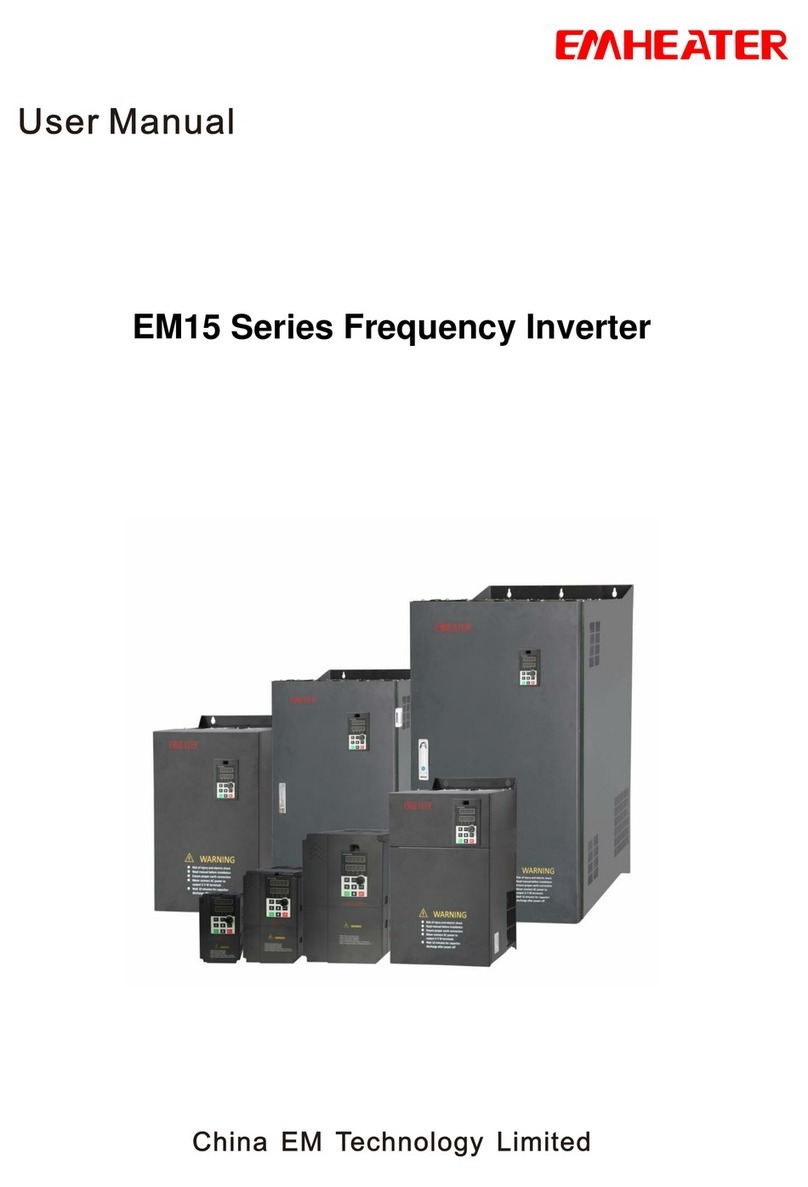
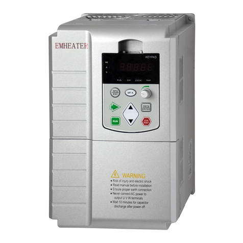
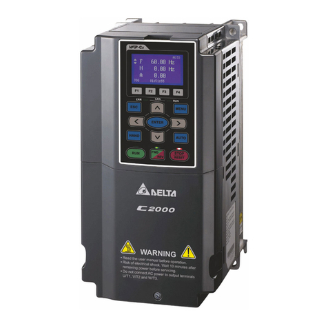
Emheater EM8 Series User manual

User’s Manual
China EM Technology Limited
Address:No.80, Baomin 2 road, Xixiang, Bao'an District,Shenzhen ,China
Phone: 86-0755-29985851
Fax: 86-0755-29970305
Zip code: 518101
Website : Http://www.emheater.com China EM Technology Limited
EMHEATER
EM8 Series Frequency Inverter
EM8 Series Inverter User’s Manual

EM8 User's Manual Foreword
Foreword
Thanks for using EMHEATER EM8 series inverter.
EM8 series inverter is China EM Technology Limited adopted the new concept to research and developed
high-performance product; With unique control model, this inverter can realize high torque, high precision,
wide variable speed and low noise drive; With more superior performance than similar products, EM8
inverters have practical PID regulation, simple PLC, flexible input and output terminals, parameter online
modification, automatic identification signal transmission failure, parameter storage of power outages and
stop, fixed length control, swing frequency control, main and auxiliary given control, field bus control and
a series of practical operation, control function, which provide a highly integrated solution for equipment
manufacturers and terminal customers, in speed, energy saving, protection, automatic control and other
aspects. EM8 inverter has great value to reduce the purchase and operating costs, enhance the reliability of
customers’system.
Before installation, use and maintenance of this inverter, the relevant personnel please read the user manual
carefully, to ensure the correct installation and operation of this product, make it play its best performance.
As for any query of frequency inverter application or having special requirements, you can feel free to
contact my company's agents, but also can directly call our company after sale service department; we will
make effort to service well for you.
This manual copyright belongs to China EM Technology Limited; please forgive without notice of revise.
Version:201302

EM8 User's Manual Table of Contents
I
Table of Contents
1. Caution........................................................................................................................................................1
1.1 Safety caution clause.........................................................................................................................1
1.1.1 To get the product's confirmation...........................................................................................1
1.1.2 Installation..............................................................................................................................1
1.1.3 Wiring.....................................................................................................................................1
1.1.4 Running, maintenance, inspection..........................................................................................1
1.2 Precaution of use...............................................................................................................................2
1.2.1 Motor insulation confirmation................................................................................................2
1.2.2 Negative torque load ..............................................................................................................2
1.2.3 Mechanical resonance of load equipment ..............................................................................2
1.2.4 The capacitor and piezoresistor of improving power factor of electricity..............................2
1.2.5 To drop down KW because of basic frequency setting...........................................................2
1.2.6 Running upper 50Hz ..............................................................................................................2
1.2.7 Electronic thermal protection of motor ..................................................................................2
1.2.8 To drop down KW because of altitude...................................................................................2
1.2.9About IP..................................................................................................................................3
1.3 End of life caution.............................................................................................................................3
2. Installation and Wiring................................................................................................................................4
2.1 EM8 series inverter model explanation.............................................................................................4
2.2 Specification......................................................................................................................................5
2.3 Installation size of inverter................................................................................................................7
2.4 Cable sectional area of inverter and breaker .....................................................................................9
2.5 EM8 inverter circuit diagram..........................................................................................................10
2.6 Main circuit terminal explanation ...................................................................................................11
2.7 Terminal of control circuit
...............................................................................................................13
2.7.1 Explanation of terminals of control circuit...........................................................................14
2.8 JP jumper explanation .....................................................................................................................15
3. Operation and Running .............................................................................................................................16
3.1 The panel layout..............................................................................................................................16
3.2 The eM8 series frequency inverter parameter categories................................................................16
3.2.1 Basic parameter....................................................................................................................16
3.2.2 Intermediate parameters .......................................................................................................16
3.2.3 Senior parameters:................................................................................................................16
3.3 Working model of panel..................................................................................................................17
3.3.1 Monitoring state mode..........................................................................................................17
3.3.2 Parameter setting mode ........................................................................................................17
3.3.3 Checking mode of monitoring parameter.............................................................................17
3.3.4 The revise mode of digital setting frequency .......................................................................17
3.4 Parameter explanation.....................................................................................................................17
3.5 Panel function description...............................................................................................................17
3.6 Running way of panel .....................................................................................................................18
3.6.1Switching mode.....................................................................................................................18
3.6.2Monitor parameter inquiry ....................................................................................................19
3.6.3 Setting parameter..................................................................................................................19
3.6.4 Modification of digital setting frequency.............................................................................19
4. Function Parameter List ............................................................................................................................21

Table of Contents EM8 User's Manual
II
4.1 Basic running parameters (Group A)...............................................................................................21
4.2 Intermediate running parameters (Group B) ...................................................................................23
4.3 Advanced running parameters (Group C)........................................................................................27
4.4 State monitor parameter list ............................................................................................................31
4.5 Protection and solution....................................................................................................................33
4.6 Fault record inquiry.........................................................................................................................35
5. The Concrete Explanation of Function Parameters...................................................................................36
5.1 Inverter running parameters (Group A)...........................................................................................36
5.2 Intermediate running parameters (Group B) ...................................................................................44
5.3 Advanced running parameter (Group C).........................................................................................60
6. Care and Maintenance...............................................................................................................................76
6.1 Daily inspections and maintenance.................................................................................................76
6.2 Periodic maintenance ......................................................................................................................76
6.2.1 Inspection content.................................................................................................................77
6.3 Inspection and replacement of damageable parts............................................................................77
6.3.1 Filtering capacitors...............................................................................................................77
6.3.2 Cooling fan...........................................................................................................................77
6.4 Storage and warranty.......................................................................................................................77
6.4.1 Storage..................................................................................................................................77
6.4.2 Warranty...............................................................................................................................77
7. Application Examples ...............................................................................................................................79
7.1 Panel control: start and stop, panel potentiometer set frequency ....................................................79
7.1.1 Parameter settings.................................................................................................................79
7.1.2 Basic wiring diagram............................................................................................................79
7.1.3 Running description .............................................................................................................79
7.2 Three wire control mode .................................................................................................................79
7.2.1 Parameter settings.................................................................................................................79
7.2.2 The basic diagram ................................................................................................................80
7.2.3 Operating instructions ..........................................................................................................80
7.3 External control mode, external voltage setting frequency.............................................................80
7.3.1 Parameter settings.................................................................................................................80
7.3.2 The basic wiring...................................................................................................................80
7.3.3 Operating instructions ..........................................................................................................80
7.4 Multi-step speed running, external control mode............................................................................81
7.4.1 Parameter settings.................................................................................................................81
7.4.2 Basic wiring diagram............................................................................................................81
7.4.3 Operating instructions ..........................................................................................................81
7.5 Programmable multi-step speed control..........................................................................................81
7.5.1 Parameter settings.................................................................................................................81
7.5.2 Basic wiring..........................................................................................................................82
7.5.3 Operating instructions ..........................................................................................................82
7.6 The linkage control of many frequency inverter (Group Control)..................................................82
7.6.1 To use external voltage to realize many sets of inverter linkage control .............................82
7.6.1.1 Parameter Setting ......................................................................................................82
7.6.1.2 The basic diagram......................................................................................................82
7.6.1.3 Operating instructions ...............................................................................................83
7.6.2 Using RS485 constitute a linkage running...........................................................................83
7.6.2.1 Parameter settings......................................................................................................83
7.6.2.2 Basic wiring diagram.................................................................................................84

EM8 User's Manual Table of Contents
III
7.6.2.3 Operating instructions ...............................................................................................84
7.7 Inverters constitute a closed-loop control system............................................................................85
7.7.1 Parameter settings.................................................................................................................85
7.7.2 Wiring...................................................................................................................................85
7.8 Use upper computer (PC) control many sets frequency inverters...................................................85
7.8.1 Parameter settings.................................................................................................................85
7.8.2 Basic wiring diagram............................................................................................................85
7.8.3 Operating instructions ..........................................................................................................86
8. Optional Accessories.................................................................................................................................87
8.1 Remote control cable and adapter...................................................................................................87
8.2 Braking accessories.........................................................................................................................87
Appendix 1: RS485 Communication Protocol..............................................................................................88
1. Summary ...........................................................................................................................................88
1.1 Content of communication protocol........................................................................................88
1.2 Scope of application................................................................................................................88
1.2.1Applicabledevices........................................................................................................88
1.2.2Applicationtype ...........................................................................................................88
2. Bus structure and specification of communication protocol .............................................................88
2.1 Bus structure............................................................................................................................88
2.2 Specification of communication protocol ...............................................................................88
2.2.1 Data Format..................................................................................................................88
2.2.2 Baud rate ......................................................................................................................89
2.2.3 Communication mode ..................................................................................................89
2.2.4 Communication rules
...................................................................................................89
2.3 Structure of message ...............................................................................................................89
2.3.1 Master command frame................................................................................................90
2.3.2 Slave response frame....................................................................................................90
2.4 Message data encoding............................................................................................................90
2.4.1 Frame header................................................................................................................90
2.4.2 Data of user ..................................................................................................................90
2.4.3 Frame footer(checksum)...............................................................................................93
3. Example of using...............................................................................................................................94

1.Caution EM8 User's Manual
1
1. Caution
To ensure that you're personal, equipment and property safety, in use before frequency inverter, please be
sure to read this chapter content, and comply with in the later carry, installation, running, debugging and
maintenance, running process.
Warning
●This symbol can lead to death, serious injury or heavy losses of property.
Caution
●This symbol can lead to body moderate damage or minor injuries, equipment damage.
1.1 Safety caution clause
1.1.1 To get the product's confirmation
Caution:
●The damaged and lack of parts of the frequency inverter, do not install. Or you risk of injury.
1.1.2 Installation
Caution
●When carrying, please take the bottom of inverter, otherwise the inverter body may lose and hurt your
foot.
●Please install in metal materials plate burning not easily. If installed near flammable materials, there is
danger of fire.
1.1.3 Wiring
Warning
●Before wiring, please confirm the input power has cut off.
●Please let electrical engineering personnel wiring homework.
●Grounding terminals must be reliable grounding.
●Prohibit to input the power to output U, V, W terminal. Add in the output terminal voltage will lead
frequency inverter internal damage.
●The emergency stop terminal after wiring, please check its actions are effective. Or you risk of injury.
●Prohibit to touch output terminal, short connect output terminals and shell and between output terminals.
Caution
●Please confirm the input power voltage is the same as inverter rated voltage.
●Please do not do withstand voltage test for frequency inverter.
●please connect brake unit and resistor according to frequency inverter circuit diagram.
Otherwise you may cause the damage of the semiconductor components, etc.
1.1.4 Running, maintenance, inspection
Warning
●Prohibit to touch inverter input and output terminals
●Before power on, please install terminal house properly, before you take off terminal house, please make
sure power off.
●Amateur technicians, please do not for maintenance and inspection.

EM8 User's Manual 1.Caution
2
Caution
●The panel board, control circuit board, driving circuit boards installed the CMOS integrated circuit, when
using, please pay special attention, Directly with finger touch circuit boards, electrostatic induction it might
damage the circuit boards integrated chips.
●Power on, please do not change wiring or remove the terminal wiring. Have the risk of damage to
equipment.
1.2 Precaution of use
In using of frequency inverter , please pay attention to following clause.
1.2.1 Motor insulation confirmation
When use inverter, please make sure motor insulation to avoid damaging other equipment. In the motor
environment is poor, please routine check the insulation of the motor to ensure the safety of the system.
1.2.2 Negative torque load
Such as load of lift and elevator is negative torque load, the system will feedback current to inverter, so
please consider to match optional braking resistor.
1.2.3 Mechanical resonance of load equipment
Inverter in certain output frequency range, may meet load mechanical resonance, must be set to avoid
jumping through this frequency.
1.2.4 The capacitor and piezoresistor of improving power factor of electricity
As the inverter output voltage is pulse wave, so the output side cannot connect capacitor and piezoresistor,
which will damage inverter, please take off. At same time, please do not add air switch and contactor on
output of inverter. For 1-1 diagram, (if you must add switch device, please make sure the inverter no output
current, and then you can take on-off switch).
Diagram 1-1:Prohibit to connect capacitor on output of inverter
1.2.5 To drop down KW because of basic frequency setting
When basic frequency setting is lower than rated frequency, please drop down the KW of matched motor in
avoiding motor overheat burnt.
1.2.6 Running upper 50Hz
If inverter output is upper 50Hz, except consider motor vibration, noise, please consider the rated speed of
your motor avoiding damaging motor.
1.2.7 Electronic thermal protection of motor
When properly matched motor, inverter has thermal protection for motor. If inverter is not proper
matched with motor, please adjust relative parameter to protect motor.
1.2.8 To drop down KW because of altitude
When the altitude is higher than 1000m, the inverter must be drop down to match motor because of thin air
poor the cooling effect. As diagram 1-2 is the relationship curve of inverter rated current and altitude.

1.Caution EM8 User's Manual
3
Diagram 1-2: The curve relationship of output current and altitude
1.2.9About IP
Our inverter is IP20, you can add cabinet to improve its protection level.
1.3 End of life caution
When you end of inverter life:
The capacitor of main circuit and board can not burn, it will explode; Plastic house cannot burn, it will emit
toxic gas, please deal with it as industrial refuse.

EM8 User's Manual 2.Installation and Wiring
4
2. Installation and Wiring
2.1 EM8 series inverter model explanation
Model No. Voltage Power Current G.W Inverter size
G series P series (V) (KW) (A) (KG) H/W/D(mm)
EM8-G1-d75 -- 220 0.75 5 2 150/85/115
EM8-G1-1d5 -- 220 1.5 7.5
EM8-G1-2d2 -- 220 2.2 10
3 173/133/133
EM8-G3-d75 EM8-P3-1d5 380 0.75 2.5
EM8-G3-1d5 EM8-P3-2d2 380 1.5 3.7
EM8-G3-2d2 EM8-P3-004 380 2.2 5
EM8-G3-004 EM8-P3-5d5 380 4.0 8.5 4 235/137/175
EM8-G3-5d5 EM8-P3-7d5 380 5.5 11 7 305/208/185
EM8-G3-7d5 EM8-P3-011 380 7.5 17
EM8-G3-011 EM8-P3-015 380 11 25
12 390/240/235
EM8-G3-015 EM8-P3-018 380 15 33
EM8-G3-018 EM8-P3-022 380 18.5 39
EM8-G3-022 EM8-P3-030 380 22 45 21 460/260/248
EM8-G3-030 EM8-P3-037 380 30 60
EM8-G3-037 EM8-P3-045 380 37 75 40 580/320/295
EM8-G3-045 EM8-P3-055 380 45 90
EM8-G3-055 EM8-P3-075 380 55 110 45 590/380/312.5
EM8-G3-075 EM8-P3-093 380 75 150
EM8-G3-093 EM8-P3-110 380 93 176 95 744/512/273
EM8-G3-110 EM8-P3-132 380 110 210
EM8-G3-132 EM8-P3-160 380 132 250
140 793/583/315
EM8-G3-160 EM8-P3-185 380 160 300
EM8-G3-185 EM8-P3-200 380 185 340
EM8-G3-200 EM8-P3-220 380 200 380
EM8-G3-220 EM8-P3-250 380 220 415
300 1172/790/397
EM8-G3-250 EM8-P3-280 380 250 470
EM8-G3-280 EM8-P3-315 380 280 520
EM8-G3-315 EM8-P3-350 380 315 600 450 1828/981/496

2.Installation and Wiring EM8 User's Manual
5
Model No. Voltage Power Current G.W Inverter size
EM8-G3-350 EM8-P3-400 380 350 640
450 1828/981/496
EM8-G3-400 EM8-P3-500 380 400 690
EM8-G3-500 EM8-P3-630 380 500 860
EM8-G3-630 -- 380 630 1100
2.2 Specification
Items Specification
Input Rated voltage and frequency Single phase 220/Three Phase 380V, 50/60Hz
Voltage allowable deviation range 200V~240V,320V~460V
Output
Voltage 0~380V
Frequency 0Hz~500Hz
Over-load capability
G3 Series:
150% rated current for 1 minute
180% rated current for 2seconds
P3 Series:
120% rated current for 1 minute
150% rated current for 2seconds
Control
character
Control mode V/F Control
Frequency
setting
resolution
Analog terminal input 0.1% of max output frequency
Digital setting 0.01Hz
Panel analog setting 0.4 % of max frequency
External pulse 0.1% of max frequency
Frequency
accuracy
Analog Input Within ±0.2% of max. output frequency
Digital Input Within ±0.01% of setting output frequency
External pulse Within ±0.1% of max. output frequency
V/F curve
(Voltage-frequency character)
Base frequency can be set from 5~500Hz arbitrarily,
and there are three kinds of curve: constant
torque ,Dec torque 1 and Dec torque 2.
Torque boost
Manual Setting: 0~20% of rated output, Auto-boost:
Automatically boost torque according to output
current.
Auto energy-saving running
Adjust output voltage and slip compensation properly
according to output current, which will make the
motor working in highest efficiency.
Acc./Dec time setting 0.1~6000seconds can be set continuously, and S type
and line type can be selected.
Braking
Dynamic braking Over 75% (External braking resistor)
DC braking
It is selected respectively at start and stop, and its
frequency is 0~15Hz, the action voltage is 0~15%, and
the action time is 0~20.0 second or act continuously.
Auto current-limiting function
Fast auto current-
limiting function ensures not to occur
the over-current during the accelerate process or under
the impact load.

EM8 User's Manual 2.Installation and Wiring
6
Items Specification
Control
character
Overvoltage prevention Ensure not over-voltage in Dec process.
Low noise running
Carrier
freq. can be adjusted continuously form
1.5KHz to 15.0KHz, which can reduce the motor’s
noise furthest.
Speed tracking restart It can realize the smoothness restart and
instantaneous stop then restart function.
Freq
setting
signal
Analog input DC voltage 0~10V,-10V~10V, DC current 0~20mA
(Upper limit and Lower limit can be selected).
Digital setting By the running panel.
Pulse input 0~50.000kHz (Upper limit and Lower limit can be
selected)
Startup signal FWD, REV, startup signal can be selected and
self-keep (Three line control).
Timer and Counter Embedded one timer and one counter , which will
help the system’s integration.
Multi-speed control function /
Wobble frequency
Seven steps programmable multi-
speed control at
most, every step’s running dire
ction, running time
can be set respectively. In external terminal control,
It reaches 15 steps, and there are 6 kind of running
modes. Include wobble frequency.
Built-in
PID
control
Common PID Expediently compose the simple control system
without accessional PID controller.
Special for water
supply
(Need accessories)
Make it possible to construct the constant-pressure
water-
supply system of 4 pumps switch at most,
which includes the following functions: pressure
upper or Lower limit alarm, Sleep or wake, Timing
water-supply etc. multi kind running mode.
Running function
Setting the
upper and lower limit of frequency,
frequency jump-running, reversal running limit, slip
frequency compensation, auto constant-voltage
running, RS485 communication frequency increment
and decrement control, fault self-
restore running,
multi inverter coupled running.
Output
signal
Running status
(OC Output)
During the running of inverter, f
requency arrival,
frequency level detection, over-
load alarm, and
external fault stop-machine. Frequency upper-limit
arrival, Frequency lower-limit arrival, under-voltage
stop, zero-speed running, programmable multi-speed
running state, Internal counter arrival, Internal timer
arrival, pressure lower-upper limit alarm.
Indicating meter
Output Frequency, output current, o
utput voltage,
motor speed, PID setting and feedback, external
voltmeter, external cymometer.

2.Installation and Wiring EM8 User's Manual
7
Items Specification
Display
Running
panel
display
Running status
Output Frequency, output current, o
utput voltage,
motor rotate speed, setting frequency
, PID setting,
PID feedback, model temperature, accumulative
running time, analog I/O, terminal Input status.
Alarm content
Last six fault records, output frequency, setting
frequency, output current, o
utput voltage, DC
voltage, model temperature, t
erminal status,
accumulative running time of Last fault trip.
Protective / Alarm function Over-current, over-voltage, under voltage, electronic
thermal protection, over-heat, short-circuit.
Operating
Environ-
ment
Temperature -10ºC to +50ºC
(Put down one grade capacity in 40 ºC ~50 ºC)
Humidity Below 90%RH(non-dewing)
Ambient environment Indoors (no inflammable gasses or dust)
Altitude Under 1000m
Structure Protective class IP20
Cooling method Fans cooling
Mounting model Wall mounting
2.3 Installation size of inverter
Diagram 2-1: Installation size of inverter
Inverter model W1
(mm) W
(mm) H1
(mm) H
(mm) D1
(mm) D
(mm) Screw
standard
G Series
EM8-G1/G3 P Series
EM8-P3
EM8-G1-d75
77 89 145 155 116 126 M4
EM8-G1-1d5
EM8-G1-2d2
123
133
163
173
123
133
M4
EM8-G3-d75
EM8-P3-1d5
126 136 163 173 123 133 M4
EM8-G3-1d5
EM8-P3-2d2
EM8-G3-2d2
EM8-P3-004
EM8-G3-004
EM8-P3-5d5
123
137
225
235
160
175
M4

EM8 User's Manual 2.Installation and Wiring
8
Inverter model W1
(mm) W
(mm) H1
(mm) H
(mm) D1
(mm) D
(mm) Screw
standard
G Series
EM8-G1/G3 P Series
EM8-P3
EM8-G3-5d5 EM8-P3-7d5 190 208 285 305 170 185 M4
EM8-G3-7d5 EM8-P3-011
EM8-G3-011 EM8-P3-015
190 240 372 390 220 235 M6
EM8-G3-015 EM8-P3-018
EM8-G3-018 EM8-P3-022
EM8-G3-022 EM8-P3-030 242 260 440.5 460 233 248 M6
EM8-G3-030 EM8-P3-037
EM8-G3-037 EM8-P3-045 283 320 550 580 280 295 M6
EM8-G3-045 EM8-P3-055
EM8-G3-055 EM8-P3-075 320 380 568 590 297.5 312.5 M8
EM8-G3-075 EM8-P3-093
EM8-G3-093 EM8-P3-110 445 512 714 744 258 273 M8
EM8-G3-110 EM8-P3-132
EM8-G3-132 EM8-P3-160
515 583 760 793 300 315 M8
EM8-G3-160 EM8-P3-185
EM8-G3-185 EM8-P3-200
EM8-G3-200 EM8-P3-220
Cabinet inverter:
Inverter model W
(mm) H
(mm) D
(mm)
G Series
EM8-G1/G3 P Series
EM8-P3
EM8-G3-220 EM8-P3-250
790 1172 397
EM8-G3-250 EM8-P3-280
EM8-G3-280 EM8-P3-315
EM8-G3-315 EM8-P3-350
981 1828 496
EM8-G3-350 EM8-P3-400
EM8-G3-400 EM8-P3-500
EM8-G3-500 EM8-P3-630
Panel size is as diagram 2-2:
Suitable for: Suitable for:
EM8-G1-d75~EM8-G1-2d2 EM8-G3-004~EM8-G3-630
EM8-G3-d75~EM8-G3-2d2 EM8-P3-5d5~EM8-P3-630
Diagram 2-2: Digital display running panel size

2.Installation and Wiring EM8 User's Manual
9
The running panel disassemble and installation
Disassemble: Put your finger into the hole above panel and gently press down the fixed shrapnel, and then
take off key panel.
Installation: Put the panel into the slot until to hear a voice "click".
Inverter installation direction and space
The EM8 series frequency inverter for wall hung should be installed vertically for air circulation and heat
dissipation. The reserved space around inverter should be according to diagram 2-3. The fan of inverter
cabinet should be according to the diagram 2-4 correct way. The installation of many pcs inverters should
be installed as diagram 2-5 and diagram 2-6. As in the same vertical direction and installation, please note
that application of diversion board.
Diagram 2-3: Inverter around space Diagram 2-4: Cabinet fan correct way
Diagram 2-5: The air division board Diagram 2-6: Many pcs inverter installation
2.4 Cable sectional area of inverter and breaker
Please refer the following data to choose breaker capacity and cable sectional area.
Model
EM8-G/P
Input side
Main circuit(mm2)
Control circuit(mm2)
Breaker(A)
Input cable
Output cable
Control cable
G3/P3-d75
10
2.5
2.5
1
G3/P3-1d5
10
2.5
2.5
1
G3/P3-2d2
10
2.5
2.5
1
G3/P3-004
16
4
4
1
G3/P3-5d5
20
4
4
1
G3/P3-7d5
25
6
6
1
G3/P3-011
40
10
10
1
G3/P3-015
50
10
10
1
G3/P3-018
63
16
16
1
G3/P3-022
63
16
16
1
G3/P3-030
100
25
25
1

EM8 User's Manual 2.Installation and Wiring
10
Model
EM8-G/P
Input side
Main circuit(mm2)
Control circuit(mm2)
Breaker(A)
Input cable
Output cable
Control cable
G3/P3-037
125
25
25
1
G3/P3-045
160
35
35
1
G3/P3-055
160
35
35
1
G3/P3-075
250
50
50
1
G3/P3-090
250
70
70
1
G3/P3-110
315
70
70
1
G3/P3-132
400
95
95
1
G3/P3-160
630
120
120
1
G3/P3-185
630
150
150
1
G3/P3-200
630
150
150
1
G3/P3-220
630
150
150
1
G3/P3-250
800
150
150
1
G3/P3-280
800
185
185
1
G3/P3-315
1000
185
185
1
G3/P3-350
1000
240
240
1
G3/P3-400
1250
240
240
1
G3/P3-500
1250
300
300
1
G3/P3-630
1250
300
300
1
2.5 EM8 inverter circuit diagram
Diagram 2-7: EM8 single phase 220-240V inverter diagram

2.Installation and Wiring EM8 User's Manual
11
Diagram 2-8: EM8 Three phase 380V inverter diagram
2.6 Main circuit terminal explanation
Diagram 2-9: Main circuit terminal (1)
Series
Suitable Inverter
G1
EM8-G1-d75~EM8-G1-2d2
Terminal
mark Function explanation
L
1
,L
2
Single phase 220V AC power
U,V,W
Output three phase terminals connect with motor
E
Connect with earth terminal

EM8 User's Manual 2.Installation and Wiring
12
Diagram 2-10: Main circuit terminal (2)
Series
Suitable Inverter
G3
EM8-G3-d75~EM8-G3-2d2
P3
EM8-P3-1d5~EM8-P3-004
Terminal
mark Function explanation
P+
DC BUS positive pole
PB
The braking resistor connect between P+ and PB
R,S,T
Input three phase terminals connect with grid
U,V,W
Output three phase terminals connect with motor
E
Connect with earth terminal
Diagram 2-11: Main circuit terminal (3)
Series
Suitable Inverter
G3
EM8-G3-004~EM8-G3-018
P3
EM8-P3-5d5~EM8-P3-022
Diagram 2-12: Main circuit terminal (4)
Series
Suitable Inverter
G3
EM8-G3-022~EM8-G3-030
P3
EM8-P3-030~EM8-P3-037

2.Installation and Wiring EM8 User's Manual
13
Diagram 2-13: Main circuit terminal (5)
Series
Suitable Inverter
G3
EM8-G3-037~EM8-G3-630
P3
EM8-P3-045~EM8-P3-630
2.7 Terminal of control circuit
Diagram 2-14: Terminal of control circuit (1)
Series
Suitable Inverter
G1
EM8-G1-d75~EM8-G1-2d2
Diagram 2-15: Terminal of control circuit diagram (2)
Series
Suitable Inverter
G3
EM8-G3-d75~EM8-G3-2d2
P3
EM8-P3-1d5~EM8-P3-004
Diagram 2-16: Terminal of control circuit diagram (3)
Series
Suitable Inverter
G3
EM8-G3-004~EM8-G3-630
P3
EM8-P3-5d5~EM8-P3-630

EM8 User's Manual 2.Installation and Wiring
14
2.7.1 Explanation of terminals of control circuit
Type
Terminal
Terminal function
Notes
Analog
input
+10V/V+ Provide +5V/50mA power or +10V/10mA
power to external Selected by control panel JP1
(refer to the following diagram)
-10V/V-
Provide -10V/10mA power
V/V1
Analog input voltage signal input terminal 1
0~10V
V2
Analog input voltage signal input terminal 2
-10~10V
I
Input positive terminal of frequency setting
current signal (Current input terminal). 0~20mA
GND
Command terminal of Frequency setting
voltage signal (Power earth of V+,V- ),
Negative terminal of f
requency setting
current signal(Current output terminal).
Control
terminal
X1
Multi-function input terminal 1
The detailed function of
Multi-function input terminal
is set by parameter b-63~b-69,
the terminal is valid while
being closed with COM
terminal.
X2
Multi-function input terminal 2
X3
Multi-function input terminal 3
X4
Multi-function input terminal 4
X5
Multi-function input terminal 5
X6
Multi-function input terminal 6
PUL/X7
Multi-function input terminal 7,and it can
also be as the input terminal of
external
pulse signal (refer to the following diagram).
FWD FWD control command terminal
The terminal is valid while being
closed with COM terminal. The
close of terminals FWD and
COM decides the inverter
running direction under panel
control mode..
REV
REV control command terminal
RST
Fault resetting input terminal
COM Command terminal of control terminal
+24V
Provide +24V/50mA Power (COM is the
ground of power).
AOI
Analog voltage output, between GND and
AOI connected a current meter
AOV
Analog voltage output, between GND and
AOI connected a voltmeter
Analog
output
AO
Programmable voltage signal output
terminal can connect the external voltmeter
(set by parameter A-10).
Highest allowable Current:
1mA; Output voltage:0-10V
FM
Programmable frequency signal output
terminal can connect the external
cymometer. (Set by parameter A-11)
Max. output signal frequency:
50KHz Signal amplitude
value: 10V
OC
output OC1
OC2 Programmable open-circuit collector
output is set by parameter A-15 and A-16.
The highest loadcurrent is 50m
and The highest withstand
voltage is 24V
Fault
output TA/TB/TC Normal: TA-TB is closed, TA-TC is off
Fault : TA-TB is off, TA-TC is closed Contact capacity: AC250V 1A
resistive load
RS485
485+/485-
RS485 communication terminal
ERH E Earth terminal

2.Installation and Wiring EM8 User's Manual
15
2.8 JPjumper explanation
The 0.4KW to 4KW JP on PCB board as following diagram 2-16:
Diagram 2-17: 0.4KW~4KW Jumper
The 5.5KW to 630 KW JP on PCB board as following diagram 2-17:
Diagram 2-18: 5.5KW~630KW Jumper
This manual suits for next models
60
Table of contents
Other Emheater DC Drive manuals

