Emheater EM12 Series User manual

User ManualEM12 Series Frequency Inverter
EM12 Series Frequency Inverter
EMHEATER
China EM Technology LimitedChina EM Technology LimitedAddress:No.80, Baomin 2 road, Xixiang, Bao'an District,Shenzhen ,ChinaPhone:86-0755-29985851Fax:86-0755-29970305Zip code:518101Website :Http://www.emheater.com
EMHEATER
R
EM12 User’s Manual Preface
I
Preface
Thank you for purchasing the EM12 series frequency inverter developed by China EM Technology Limited.
The high-performance EM12 series vector control frequency inverter has the following features:
1. Multiple voltage classes
It provides coverage of single-phase 220 V, three-phase 220 V, three-phase 380 V, three-phase 480 V and
three-phase 690 V.
2. Support multiple motor types
It supports vector control of three-phase AC asynchronous motor and three-phase AC permanent magnet
synchronous motor (PMSM).
3. Diversified control modes
It supports four control modes: sensor-less vector control (SVC), closed-loop vector control (FVC) and V/F
control and V/F separately control.
4. Multiple communication protocols
It supports communication via Modbus-RTU, Profibus-DP and CANopen bus.
5. Multiple encoder types
It supports various encoders such as differential encoder, open-collector encoder, resolver and UVW encoders.
6. Super SVC algorithm
It adopts high-speed response, enhanced low-frequency loading capacity and supports torque control of SVC,
which will bring you a new using experience.
EM12 series frequency inverter is a continuable and vigorous product, and we will offer customized service to our
customers!
Before unpacking, please check carefully:
Whether the nameplate model of frequency inverter are consistent with your order ratings. The box contains
the frequency inverter, user manual.
Whether the frequency inverter is damaged during transportation. If you find any omission or damage, please
contact us or your local supplier immediately.
First-time Use
For the users who use this product for the first time, read the manual carefully. If in doubt concerning some
functions or performances, contact the technical support personnel to ensure correct use.
Due to the continuous improvement of frequency inverter, this document will be updated without prior notice.
EM12 series Frequency inverter complies with the following international standards. All products have passed the
CE certification.
IEC/EN61800-5-1: 2003 Variable speed electric drive system safety requirements;
IEC/EN61800-3: 2004 Variable speed electric drive system, Part 3: The Electro Magnetic Compatibility (EMC)
Standards of Product and its specific testing methods.
Note:
There are all parameters list integrated at appendix II.
Version:V3.2.52

Table of Contents EM12 User’s Manual
II
Table of Contents
1. Safety Information and Precautions.............................................................................................................1
1.1 Safety Information .................................................................................................................................1
1.2 General Precautions ...............................................................................................................................2
2. Product Information.....................................................................................................................................5
2.1 Designation Rules..................................................................................................................................5
2.2 Nameplate..............................................................................................................................................5
2.3 EM12 Series Frequency Inverter ...........................................................................................................5
2.4 Technical Specifications ........................................................................................................................6
2.5 Product appearance and installation dimension.....................................................................................8
2.6 Options ................................................................................................................................................ 11
2.7 Daily maintenance of frequency inverters ...........................................................................................11
2.8 Warranty Items.....................................................................................................................................12
2.9 Selection Guide of braking component ...............................................................................................13
3. Installation of Frequency Inverter .............................................................................................................16
3.1 Installation environment ......................................................................................................................16
3.2 Installation direction and space............................................................................................................16
3.3 Peripheral Devices Connection Diagram.............................................................................................17
3.4 Instructions of Main Circuit Peripheral Devices .................................................................................18
3.5 Model Selection of Main Circuit Peripheral Devices..........................................................................19
3.6 Removal and mounting of operating panel and cover .........................................................................20
3.7 Connection Terminals Diagram Description........................................................................................21
3.8 Sketch and Description of Main Circuit Terminals .............................................................................21
3.9 Cautions for Main Circuit Wiring........................................................................................................22
3.10 Control Circuit and Main Circuit Terminals Description ..................................................................24
4. Operation and display................................................................................................................................28
4.1 Instruction of operation and display ....................................................................................................28
4.2 Viewing and Modifying Function Codes.............................................................................................29
4.3 Monitoring Status Parameters..............................................................................................................29
4.4 Password Setting..................................................................................................................................30
4.5 Motor parameter auto-tuning ...............................................................................................................30
5. Description of Function Codes ..................................................................................................................31
5.1 Group b0: Basic Function Parameters .................................................................................................31
5.2 Group b1: Start/Stop Control Parameters ............................................................................................39
5.3 Group b2: Auxiliary Functions ............................................................................................................41
5.4 Group b3: Input Terminals...................................................................................................................46
5.5 Group b4: Output Terminals ................................................................................................................52
5.6 Group b5: Pulse/Analog input terminals .............................................................................................59
5.7 Group b6: Pulse/analog output terminals.............................................................................................62
5.8 Group b7: Virtual digital input (VDI)/digital output (VDO) terminals ...............................................63
5.9 Group b8: AI/AO Correction ...............................................................................................................66
5.10 Group b9: Keypad and Display .........................................................................................................67
5.11 Group bA: Communication parameters .............................................................................................70
5.12 Group bb: Fault and Protection..........................................................................................................71
5.13 Group bC: Fault detection Parameters...............................................................................................79
5.14 Group bd Motor protection................................................................................................................80
EM12 User’s Manual Table of Contents
III
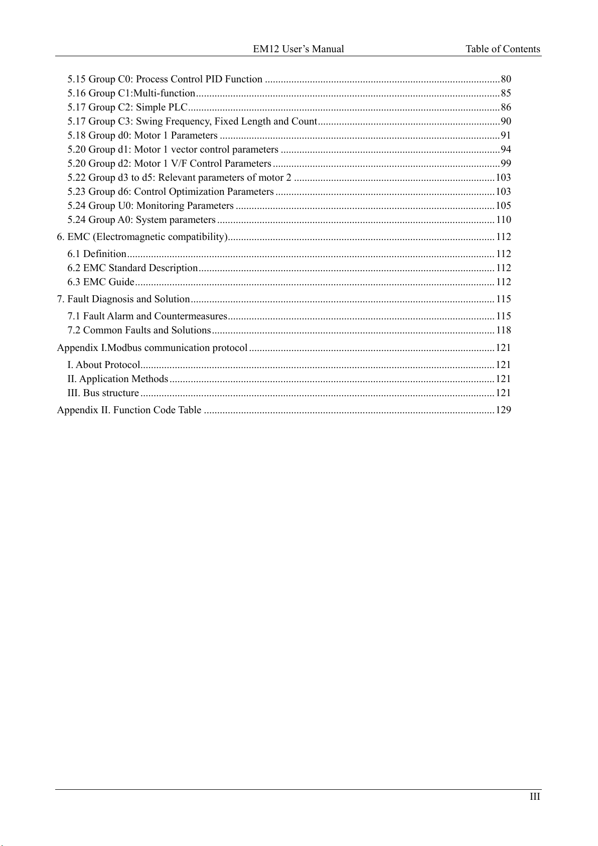
5.15 Group C0: Process Control PID Function .........................................................................................80
5.16 Group C1:Multi-function...................................................................................................................85
5.17 Group C2: Simple PLC......................................................................................................................86
5.17 Group C3: Swing Frequency, Fixed Length and Count.....................................................................90
5.18 Group d0: Motor 1 Parameters ..........................................................................................................91
5.20 Group d1: Motor 1 vector control parameters ...................................................................................94
5.20 Group d2: Motor 1 V/F Control Parameters ......................................................................................99
5.22 Group d3 to d5: Relevant parameters of motor 2 ............................................................................103
5.23 Group d6: Control Optimization Parameters ...................................................................................103
5.24 Group U0: Monitoring Parameters ..................................................................................................105
5.24 Group A0: System parameters .........................................................................................................110
6. EMC (Electromagnetic compatibility)..................................................................................................... 112
6.1 Definition........................................................................................................................................... 112
6.2 EMC Standard Description................................................................................................................ 112
6.3 EMC Guide........................................................................................................................................ 112
7. Fault Diagnosis and Solution................................................................................................................... 115
7.1 Fault Alarm and Countermeasures..................................................................................................... 115
7.2 Common Faults and Solutions........................................................................................................... 118
Appendix I.Modbus communication protocol .............................................................................................121
I. About Protocol......................................................................................................................................121
II. Application Methods ...........................................................................................................................121
III. Bus structure ......................................................................................................................................121
Appendix II. Function Code Table ..............................................................................................................129

EM12 User’s Manual 1. Safety Information and Precautions
1
1. Safety Information and Precautions
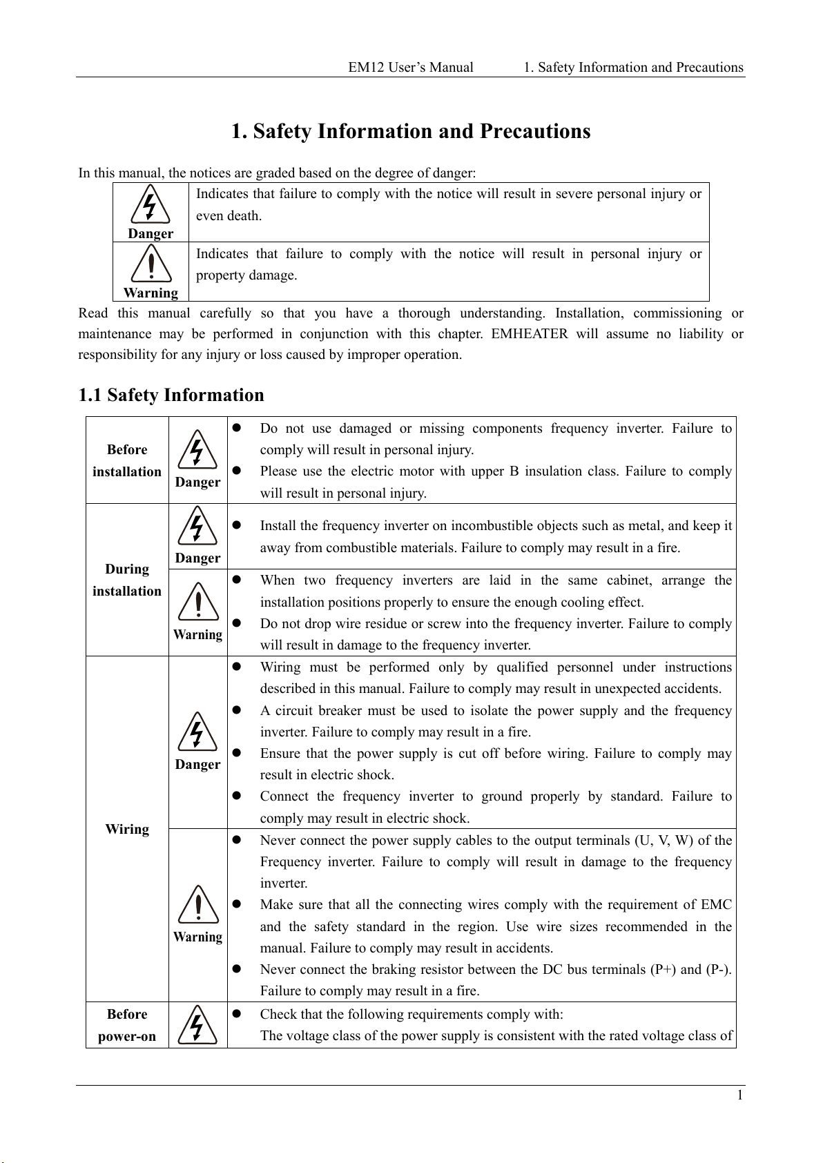
In this manual, the notices are graded based on the degree of danger:
Danger
Indicates that failure to comply with the notice will result in severe personal injury or
even death.
Warning
Indicates that failure to comply with the notice will result in personal injury or
property damage.
Read this manual carefully so that you have a thorough understanding. Installation, commissioning or
maintenance may be performed in conjunction with this chapter. EMHEATER will assume no liability or
responsibility for any injury or loss caused by improper operation.
1.1 Safety Information
Before
installation Danger
Do not use damaged or missing components frequency
inverter. Failure to
comply will result in personal injury.
Please use the electric motor with upper B insulation class. Failure to comply
will result in personal injury.
During
installation
Danger
Install the frequency
inverter on incombustible objects such as metal, and keep it
away from combustible materials. Failure to comply may result in a fire.
Warning
When two frequency inverters are laid in the same cabinet, arrange the
installation positions properly to ensure the enough cooling effect.
Do not drop wire residue or screw into the frequency inverter. Failure to comply
will result in damage to the frequency inverter.
Wiring
Danger
Wiring must be performed only by qualified
personnel under instructions
described in this manual. Failure to comply may result in unexpected accidents.
A circuit breaker must be used to isolate the power supply and the frequency
inverter. Failure to comply may result in a fire.
Ensure that the powe
r supply is cut off before wiring. Failure to comply may
result in electric shock.
Connect the frequency inverter to ground properly by standard. Failure to
comply may result in electric shock.
Warning
Never connect the power supply cables to the
output terminals (U, V, W) of the
Frequency inverter. Failure to comply will result in damage to the frequency
inverter.
Make sure that all the connecting wires comply with the requirement of EMC
and the safety standard in the region. Use wire sizes recomm
ended in the
manual. Failure to comply may result in accidents.
Never connect the braking resistor between the DC bus terminals (P+) and (P-).
Failure to comply may result in a fire.
Before
power-on
Check that the following requirements comply with:
The voltage class of the power supply is consistent with the rated voltage class of

1. Safety Information and Precautions EM12 User’s Manual
2
Danger
the frequency inverter. The input terminals (R, S, T) and output terminals (U, V,
W) are properly connected. No short-circuit exists in
the peripheral circuit. The
wiring is fastened. Failure to comply will result in damage to frequency inverter.
Cover the frequency inverter properly before power-on to prevent electric shock.
Before
power-on
Warning
Do not perform the voltage resistance
test on any part of the frequency inverter
because such test has been done in the factory. Failure to comply will result in
accidents.
All peripheral devices must be connected properly under the instructions
described in this manual. Failure to comply will result in accidents.
After
power-on
Danger
Do not open the frequency inverter’s cover after power-
on to prevent from
electric shock.
Do not touch the frequency inverter with wet hand and its peripheral circuit to
prevent from electric shock.
Do not touch the terminals of the frequency inverter (including the control
terminals). Failure to comply may result in electric shock.
Do not touch the U, V, W terminal or motor connecting terminals when
frequency inverter automatically does safety testing for the external high-
voltage
electrical circuit. Failure to comply may result in electric shock.
Warning
Note the danger during the rotary running of motor when check the parameters.
Failure to comply will result in accidents.
Do not change the factory default settings of the frequency inverter. Failure to
comply will result in damage to the frequency inverter.
During
operation
Danger
Do not go close to the equipment when selected the restart
function. Failure to
comply may result in personal injury.
Do not touch the fan or the discharging resistor to check the temperature. Failure
to comply will result in personal injury.
Signal detection must be performed only by qualified personal during operation
Warning
Avoid objects falling into the frequency inverter when it is running. Failure to
comply will result in damage to frequency inverter.
Do not start/stop the frequency inverter by turning the contactor ON/OFF.
Failure to comply will result in damage to the frequency inverter.
Maintenance
Danger
Do not repair or maintain the frequency inverter at power-
on. Failure to comply
will result in electric shock.
Repair or maintain the frequency inverter only after the
charge light on
frequency inverter is powered off. This allows for the residual voltage in the
capacitor to discharge to a safe value. Failure to comply will result in personal
injury.
Repair or maintenance of the frequency inverter may be performed only by
qualified personnel. Failure to comply will result in personal injury or damage to
the frequency inverter.
1.2 General Precautions
1.2.1 Motor insulation test
Perform the insulation test when the motor is used for the first time, or when it is reused after being stored for a

EM12 User’s Manual 1. Safety Information and Precautions
3
long time, or in a regular check-up, in order to prevent the poor insulation of motor windings from damaging the
frequency inverter. The motor must be disconnected from the frequency inverter during the insulation test. A
500-V mega-Ohm meter is recommended for the test. The insulation resistance must not be less than 5 MΩ.
1.2.2 Thermal protection of motor
If the rated capacity of the motor selected does not match that of the frequency inverter, especially when the
frequency inverter's rated power is greater than the motor's, adjust the motor protection parameters on the
operation panel of the frequency inverter or install a thermal relay in the motor circuit for protection.
1.2.3 Running at over 50 Hz
The frequency inverter provides frequency output of 0 to 3000 Hz (Up to 300 Hz is supported if the frequency
inverter runs in FVC and SVC mode). If the frequency inverter is required to run at over 50 Hz, consider the
bearable capacity of the machine.
1.2.4 Vibration of mechanical device
The frequency inverter may encounter the mechanical resonance point at some output frequencies, which can be
avoided by setting the skip frequency.
1.2.5 Motor heat and noise
The output of the frequency inverter is pulse width modulation (PWM) wave with certain harmonic frequencies,
and therefore, the motor temperature, noise, and vibration are slightly greater than those motor runs at grid power
frequency (50 Hz).
1.2.6 Voltage-sensitive device or capacitor at output side of the Frequency inverter
Do not install the capacitor for improving power factor or lightning protection voltage-sensitive resistor at the
output side of the frequency inverter because the output of the frequency inverter is PWM wave. Otherwise, the
frequency inverter may suffer transient over current and even to be damaged.
1.2.7 Contactor at the Input/Output side of the frequency inverter
When a contactor is installed between the input side of the frequency inverter and the power supply, the frequency
inverter must not be started or stopped by switching the contactor on or off. If the frequency inverter has to be
operated by the contactor, ensure that the time interval between switching is at least one hour. Since frequently
charge and discharge will shorten the service life of the capacitor inside of frequency inverter.
When a contactor is installed between the output side of the frequency inverter and the motor, do not turn off the
contactor when the frequency inverter is active. Otherwise, IGBT modules inside of frequency inverter may be
damaged.
1.2.8 When input voltage is over rated voltage range
The frequency inverter must not be used over the allowable voltage range specified in this manual. Otherwise, the
frequency inverter's components may be damaged. If required, use a corresponding voltage transformer device.
1.2.9 Prohibition of three-phase input changed into two-phase input
Do not change the three-phase input of the frequency inverter to two-phase input. Otherwise, a fault will be result
or the frequency inverter will be damaged.
1.2.10 Surge suppressor
The frequency inverter has a built-in voltage dependent resistor (VDR) for suppressing the surge voltage. For
frequently surge place, please add extra surge voltage protection device at input side of frequency inverter.

1. Safety Information and Precautions EM12 User’s Manual
4
Note: Do not connect the surge suppressor at the output side of the AC.
1.2.11 Altitude and de-rating
In places where the altitude is above 1000 m and the cooling effect reduces due to thin air, it is necessary to
de-rate the frequency inverter. Please contact our company for technical support.
1.2.12 Some special usages
If wiring that is not described in this manual such as common DC bus is applied, please contact the agent or our
company for technical support.
1.2.13 Disposal
The electrolytic capacitors on the main circuits and PCB may explode when they are burnt. Poisonous gas is
generated when the plastic parts are burnt. Please treat them as industrial waste.
1.2.14 Adaptable Motor
The standard adaptable motor is adaptable four-pole squirrel-cage asynchronous induction motor. For other types
of motor, select a proper frequency inverter according to the rated motor current. If user uses inverter for
permanent magnet synchronous motor, please contact my company for technical support.
The cooling fan and rotor shaft of non-variable-frequency motor are coaxial, which results in reduced cooling
effect when the rotational speed decreasing. If variable speed is required, add a more powerful fan or replace it
with variable-frequency motor in applications where the motor overheats easily.
The standard parameters of the adaptable motor have been configured inside the frequency inverter. It is still
necessary to perform motor auto-tuning or modify the default values based on actual conditions. Otherwise, the
running result and protection performance will be affected.
The frequency inverter may alarm or even be damaged when short-circuit exists on cables or inside the motor.
Therefore, perform insulation short-circuit test when the motor and cables are newly installed or during routine
maintenance. During the test, make sure that the frequency inverter is disconnected from the tested parts.
EM12 User’s Manual 2. Product Information
5
2. Product Information
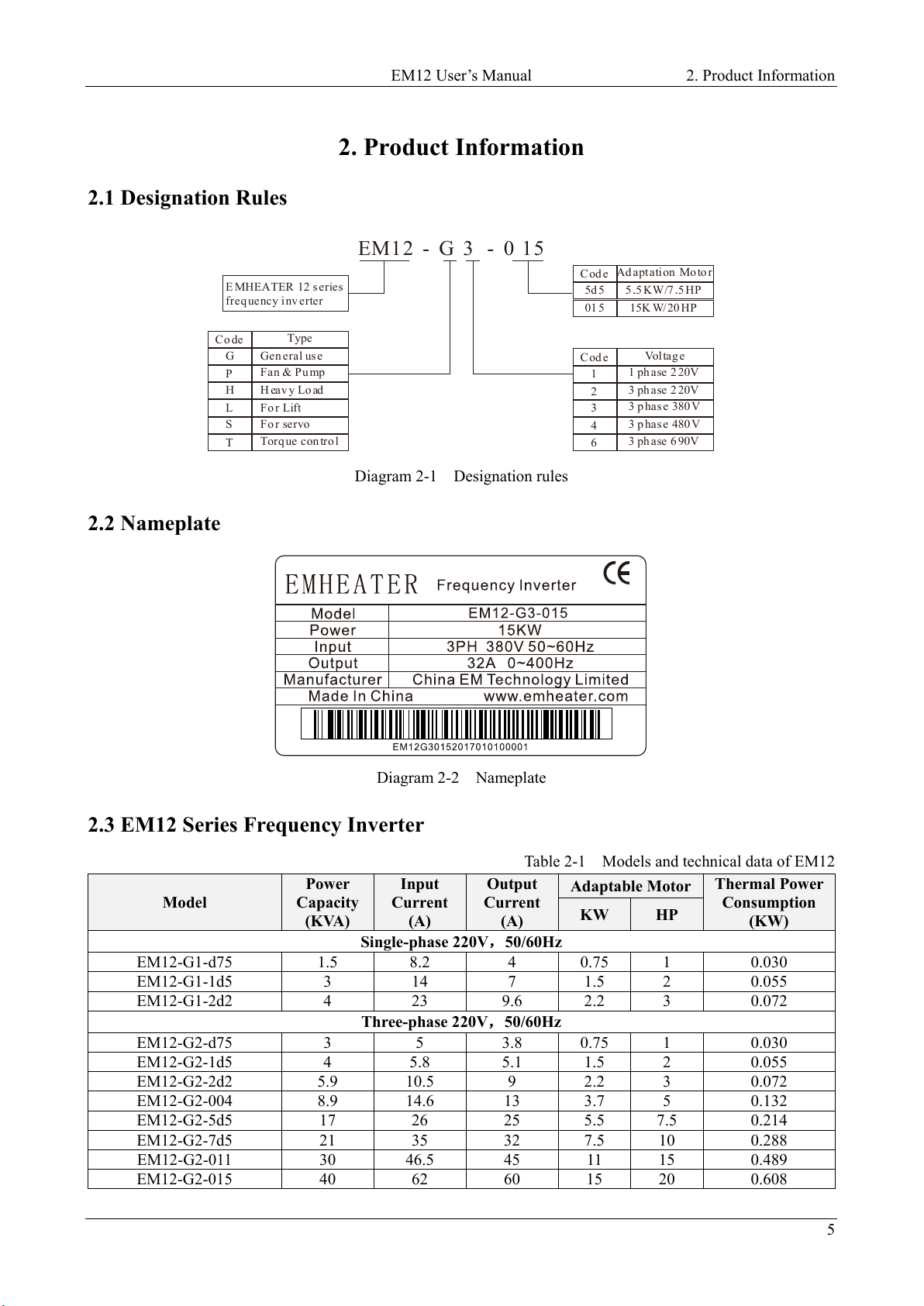
2.1 Designation Rules
E MHEATER 12 series
freq uency i nv erter
EM12 - G 3 - 0 15
Cod e Vol tag e
1
2
3
4
1 ph ase 2 20V
3 ph ase 2 20V
3 p has e 380 V
3 p has e 480 V
63 ph ase 6 90V
Cod e
5d 5
01 5
5 5 /7 5. .KW HP
15 /20K W HP
Ad apt ati on Mo to r
Co de Type
G
P
H
Gen eral us e
Fan & P u mp
H eav y Lo ad
L
S
T
Fo r Lift
Fo r servo
Torq ue con tro l
Diagram 2-1 Designation rules
2.2 Nameplate
Diagram 2-2 Nameplate
2.3 EM12 Series Frequency Inverter
Table 2-1 Models and technical data of EM12
Model
Power
Capacity
(KVA)
Input
Current
(A)
Output
Current
(A)
Adaptable Motor
Thermal Power
Consumption
(KW)
KW HP
Single-phase 220V
,
50/60Hz
EM12-G1-d75
1.5
8.2
4
0.75
1
0.030
EM12-G1-1d5
3
14
7
1.5
2
0.055
EM12-G1-2d2
4
23
9.6
2.2
3
0.072
Three-phase 220V,50/60Hz
EM12-G2-d75
3
5
3.8
0.75
1
0.030
EM12-G2-1d5
4
5.8
5.1
1.5
2
0.055
EM12-G2-2d2
5.9
10.5
9
2.2
3
0.072
EM12-G2-004
8.9
14.6
13
3.7
5
0.132
EM12-G2-5d5
17
26
25
5.5
7.5
0.214
EM12-G2-7d5
21
35
32
7.5
10
0.288
EM12-G2-011
30
46.5
45
11
15
0.489
EM12-G2-015
40
62
60
15
20
0.608

2. Product Information EM12 User’s Manual
6
Model
Power
Capacity
(KVA)
Input
Current
(A)
Output
Current
(A)
Adaptable Motor
Thermal Power
Consumption
(KW)
KW HP
EM12-G2-018
57
76
75
18.5
25
0.716
EM12-G2-022
69
92
91
22
30
0.887
EM12-G2-030
85
113
112
30
40
1.11
EM12-G2-037
114
157
150
37
50
1.32
EM12-G2-045
134
180
176
45
60
1.66
EM12-G2-055
160
214
210
55
75
1.98
EM12-G2-075
231
307
304
75
100
2.02
Three-phase 380V,50/60Hz
EM12-G3-d75/P3-1d5
3/4
5/5.8
2.1/3.8
0.75/1.5
1/2
0.050
EM12-G3-1d5/P3-2d2
4/5.9
5.8/10.5
3.8/5.1
1.5/2.2
2/3
0.066
EM12-G3-2d2/P3-004
5.9/8.9
10.5/14.6
5.1/9
2.2/3.7
3/5
0.120
EM12-G3-004/P3-5d5
8.9/11
14.6/20.5
9/13
3.7/5.5
5/7.5
0.195
EM12-G3-5d5/P3-7d5
11/17
20.5/26
13/17
5.5/7.5
7.5/10
0.262
EM12-G3-7d5/P3-011
17/21
26/35
17/25
7.5/11
10/15
0.445
EM12-G3-011/P3-015
21/24
35/38.5
25/32
11/15
15/20
0.553
EM12-G3-015/P3-018
24/30
38.5/46.5
32/37
15/18.5
20/25
0.651
EM12-G3-018/P3-022
30/40
46.5/62
37/45
18.5/22
25/30
0.807
EM12-G3-022/P3-030
40/57
62/76
45/60
22/30
30/40
1.01
EM12-G3-030/P3-037
57/69
76/92
60/75
30/37
40/50
1.20
EM12-G3-037/P3-045
69/85
92/113
75/91
37/45
50/60
1.51
EM12-G3-045/P3-055
85/114
113/157
91/112
45/55
60/75
1.80
EM12-G3-055/P3-075
114/134
157/180
112/150
55/75
75/100
1.84
EM12-G3-075/P3-090
134/160
180/214
150/176
75/90
100/125
2.08
EM12-G3-090/P3-110 160/192 214/256 176/210 90/110 125/150 2.55
EM12-G3-110/P3-132
192/231
256/307
210/253
110/132
150/200
3.06
EM12-G3-132/P3-160
231/250
307/385
253/304
132/160
200/250
3.61
EM12-G3-160/P3-200
250/280
385/430
304/377
160/200
250/280
4.42
EM12-G3-200/P3-220
280/355
430/468
377/426
200/220
280/300
4.87
EM12-G3-220/P3-250
355/396
468/525
426/465
220/250
300/370
5.51
EM12-G3-250/P3-280
396/445
525/590
465/520
250/280
370/400
6.21
EM12-G3-280/P3-315
445/500
590/665
520/585
280/315
400/420
7.03
EM12-G3-315/P3-355
500/565
665/785
585/650
315/355
420/500
7.81
EM12-G3-355/P3-400
565/630
785/883
650/725
355/400
500/530
8.51
EM12-G3-400/P3-450
630/650
883/920
725/820
400/450
530/600
9.23
EM12-G3-450/--
650
920
820
450
600
9.52
2.4 Technical Specifications
Table 2-2 Technical specifications of EM12
Item
Specifications
Standard functions
Maximum frequency
Vector control: 0~320 Hz
V/F control: 0~3200 Hz
Carrier frequency
0.5–16 kHz (The carrier frequency is automatically adjusted based on the load
features.)
Input frequency resolution
Digital setting: 0.01 Hz
Analog setting: maximum frequency x 0.025%
Control mode
Sensor-less vector control (SVC)
Closed-loop vector control (FVC)(+ PG card)
Voltage/Frequency (V/F) control
Startup torque
G type: 0.5 Hz/150% (SVC); 0 Hz/180% (FVC)
P type: 0.5 Hz/100%
Speed range
1:100 (SVC)
1:1000(FVC)

EM12 User’s Manual 2. Product Information
7
Item
Specifications
Speed stability accuracy
± 0.5% (SVC)
± 0.02% (FVC)
Torque control accuracy
± 10% (SVC)
± 5% (FVC)
Overload capacity
G type: 60s for 150% of the rated current, 3s for 180% of the rated current
P type: 60s for 120% of the rated current, 3s for 150% of the rated current
Torque boost
Auto boost
Manual boost 0.1%~30.0%
V/F curve
Straight-line V/F curve
Multi-point V/F curve
N-power V/F curve (1.2-power, 1.4-power, 1.6-power, 1.8-power, square)
V/F separation
Two types: complete separation; half separation
Acceleration/deceleration
curve
Straight-line ramp
S-curve ramp
Four groups of acceleration/deceleration time with the range of 0.0s~65000s
DC braking
DC braking frequency: 0.00 Hz ~ maximum frequency
Braking time: 0.0s~36.0s
Braking trigger current value: 0.0%~100.0%
JOG control
JOG frequency range: 0.00Hz~50.00 Hz
JOG acceleration/deceleration time: 0.00s~6500.0s
Built-in simple PLC,
multiple speeds
It realizes up to 16 speeds via the simple PLC function or combination of DI
terminal states.
Built-in PID
It realizes closed loop control system easily.
Auto voltage regulation
(AVR)
It can keep constant output voltage automatically when the mains voltage
fluctuation.
Overvoltage/ Over current
stall control
The current and voltage are limited automatically during the running process
so as to avoid frequently tripping due to overvoltage / over current.
Rapid current limit
function
It can auto limit running current of frequency inverter to avoid frequently
tripping.
Torque limit and control
(Excavator characteristics) It can limit the torque automatically and prevent
frequently over current tripping during the running process.
Torque control can be implemented in the VC mode.
Individualized functions
High performance
Control of asynchronous motor and synchronous motor are implemented
through the high-performance current vector control technology.
Instant power off not stop
The load feedback energy compensates the voltage reduction so that the
frequency inverter can continue to run for a short time.
Rapid current limit
To avoid frequently over current faults of the frequency inverter.
Virtual I/O
Five groups of virtual DI/DO can realize simple logic control.
Timing control
Time range: 0.0~6500.0 minutes
Multi-motor switchover
Two motors can be switched by two groups of motor parameters.
Multiple communication
protocols
It supports communication bus via Modbus-RTU, PROFIBUS-DP, CANlink
and CANopen.
Motor overheat protection
The optional I/O extension card enables AI3 to receive the motor temperature
sensor input (PT100, PT1000) so as to realize motor overheat protection.
Multiple encoder types
It supports various encoders such as differential encoder, open-collector
encoder, resolver, UVW encoder, and SIN/ COS encoder.
Advanced background
software
It supports the operation of frequency inverter parameters and virtual
oscillograph function, by which the state of frequency inverter can be
monitored.
RUN
Running command giving
key panel; Control terminals; Serial communication port; You can switch
between these giving in various ways.
Frequency giving
There are 10 kinds frequency giving: digital setting, analog voltage setting,
analog current setting, pulse setting and serial communication port setting.
You can switch between these giving in various ways.
Auxiliary frequency giving
There are 10 kinds auxiliary frequency giving. It can implement tiny tuning of

2. Product Information EM12 User’s Manual
8
Item
Specifications
auxiliary frequency and frequency synthesis.
Input terminal
Standard:
6 digital input (DI) terminals, one of
which supports up to 50 kHz
high-speed pulse input
3 analog input (AI) terminals, AI1,AI2 support 0V~10 V
or 0mA~20mA
input, AI3 support -10V~+10V
Expanding capacity:
many DI terminals
Output terminal
Standard:
1 high-speed pulse output terminal (open-collector) that supports 0–
50
kHz square wave signal output (Can be used as DO output)
2 relay output terminal
2 analog output (AO) terminals, both of them
supports 0mA~20mA
current output and 0V~10V voltage output.
Expanding capacity:
many DO terminals
many relay output terminals
Display and
keypad operation
LED display
It displays the parameters.
Parameters copy
Optional LCD keypad can copy parameters. (Option)
Key locking and function
selection
It can lock the keys partially or completely and define the function range of
some keys so as to prevent misoperation.
Protection mode
Motor short-circuit detection at power-on, input/output phase loss protection,
over current protection, overvoltage protection, less voltage protection,
overheat protection and overload protection,etc.
Environment
Installation location
Indoor, no direct sunlight, dust, corrosive gas, combustible gas, oil smoke,
vapour, drip or salt.
Altitude
Lower than 1000 m
Ambient temperature
-10°C~ +40°C (de-rated if the ambient temperature is between 40°C and
50°C)
Humidity
Less than 95%RH, without condensing
Vibration
Less than 5.9 m/s2 (0.6 g)
Storage temperature
-20°C ~ +60°C
2.5 Product appearance and installation dimension
2.5.1 Product appearance
Diagram 2-3 Product appearance (With potentiometer)

EM12 User’s Manual 2. Product Information
9
Diagram 2-4 Appearance and installation dimension of EM12 series (Plastic housing structure)
Diagram 2-5 Appearance and installation dimension of EM12 series (Metal housing structure)
Diagram 2-6 Appearance and installation dimension of EM12 series (Cabinet structure)

2. Product Information EM12 User’s Manual
10
The housing types of the EM12 models are listed in the following table:
1PH 220 V
3PH 220 V
3PH 380 V
Power
0.4kW
~
2.2kW
0.4kW
~
11kW
15kW
~
75kW
0.75kW
~
22kW
30kW
~
400kW
Housing Type
Plastic
Plastic
Sheet metal
Plastic
Sheet metal
2.5.2 Appearance and Installation Hole Dimension (mm)
Model
Appearance and installing dimension(mm)
W
W1
H
H1
D
D1
Φd
Single-phase 220V
EM12-G1-d75
100 89 151 140 116.5 -- Φ4
EM12-G1-1d5
EM12-G1-2d2
118
106.5
185
175.5
157
--
Φ4.5
Three-phase 220V
EM12-G2-d75
100 89 151 140 116.5 -- Φ4
EM12-G2-1d5
EM12-G2-2d2
118
106.5
185
175.5
157
--
Φ4.5
EM12-G2-004
160 148 247 235 177 -- Φ5.5
EM12-G2-5d5
EM12-G2-7d5
220 205 320 305 198 -- Φ5.5
EM12-G2-011
EM12-G2-015
300 220 540 500 240 -- Φ7
EM12-G2-018
EM12-G2-022
340 260 580 540 270 -- Φ10
EM12-G2-030
EM12-G2-037
410 260 610 575 280 -- Φ12
EM12-G2-045
EM12-G2-055
460
320
710
690
335
--
Φ12
EM12-G2-075
535
360
885
830
370
--
Φ12
Three-phase 380V
EM12-G3-d75/P3-1d5
100 89 151 140 116.5 10.5 Φ4
EM12-G3-1d5/P3-2d2
EM12-G3-2d2/P3-004
EM12-G3-004/P3-5d5
118 106.5 185 175.5 157 -- Φ4.5
EM12-G3-5d5/P3-7d5
EM12-G3-7d5/P3-011 160 148 247 235 177 -- Φ5.5
EM12-G3-011/P3-015
EM12-G3-015/P3-018
220 205 320 305 198 -- Φ5.5
EM12-G3-018/P3-022
EM12-G3-022/P3-030
EM12-G3-030/P3-037
300 220 540 500 240 -- Φ7
EM12-G3-037/P3-045
EM12-G3-045/P3-055
340 260 580 540 270 -- Φ10
EM12-G3-055/P3-075
EM12-G3-075/P3-090
410 260 610 575 280 -- Φ12
EM12-G3-090/P3-110
EM12-G3-110/P3-132
460 320 710 690 335 -- Φ12
EM12-G3-132/P3-160
EM12-G3-160/P3-185
535 360 885 830 370 -- Φ12
EM12-G3-185/P3-200
EM12-G3-200/P3-220
EM12-G3-220/P3-250
650 360 1040 985 415 -- Φ12
EM12-G3-250/P3-280
EM12-G3-280/P3-315
EM12-G3-315/P3-355
815
600
1350
1250
445
--
Φ12
EM12 User’s Manual 2. Product Information
11
Model
Appearance and installing dimension(mm)
W
W1
H
H1
D
D1
Φd
EM12-G3-355/P3-400
EM12-G3-400/P3-450
EM12-G3-450/P3-500
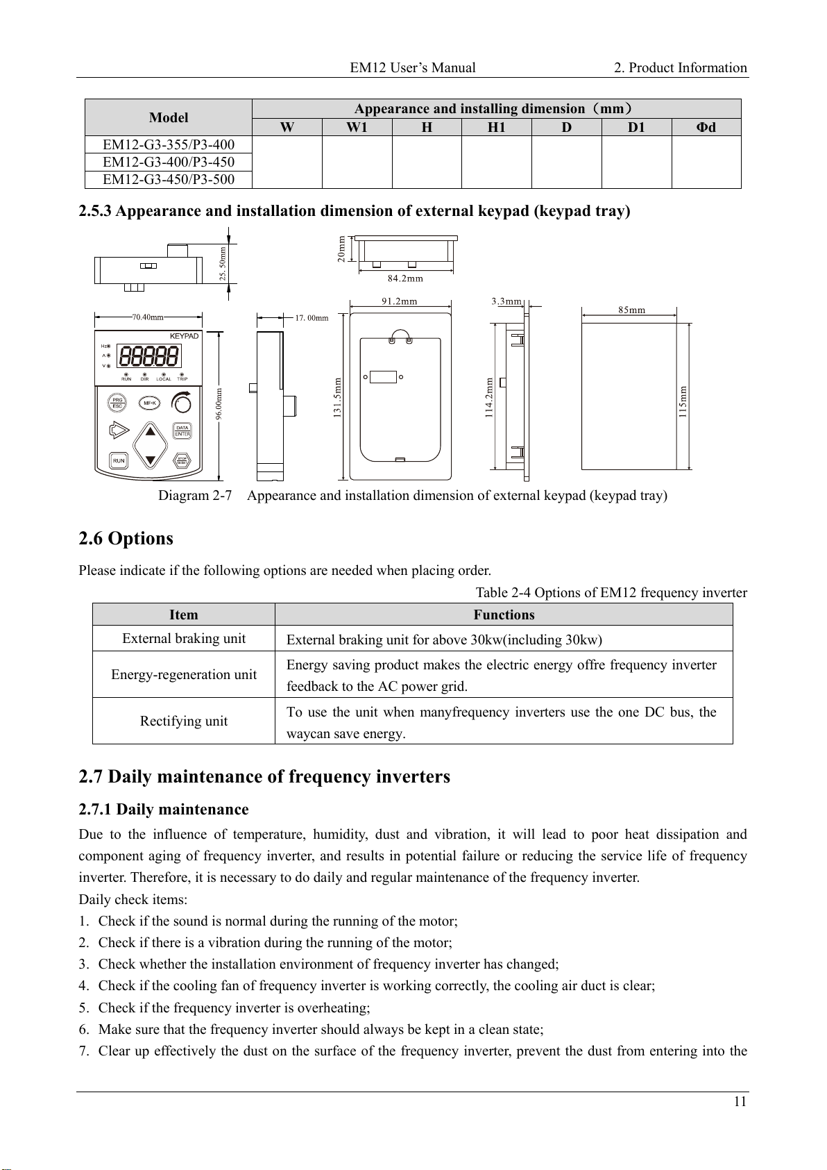
2.5.3 Appearance and installation dimension of external keypad (keypad tray)
Diagram 2-7 Appearance and installation dimension of external keypad (keypad tray)
2.6 Options
Please indicate if the following options are needed when placing order.
Table 2-4 Options of EM12 frequency inverter
Item Functions
External braking unit External braking unit for above 30kw(including 30kw)
Energy-regeneration unit Energy saving product makes the electric energy offre frequency inverter
feedback to the AC power grid.
Rectifying unit To use the unit when manyfrequency inverters use the one DC bus, the
waycan save energy.
2.7 Daily maintenance of frequency inverters
2.7.1 Daily maintenance
Due to the influence of temperature, humidity, dust and vibration, it will lead to poor heat dissipation and
component aging of frequency inverter, and results in potential failure or reducing the service life of frequency
inverter. Therefore, it is necessary to do daily and regular maintenance of the frequency inverter.
Daily check items:
1. Check if the sound is normal during the running of the motor;
2. Check if there is a vibration during the running of the motor;
3. Check whether the installation environment of frequency inverter has changed;
4. Check if the cooling fan of frequency inverter is working correctly, the cooling air duct is clear;
5. Check if the frequency inverter is overheating;
6. Make sure that the frequency inverter should always be kept in a clean state;
7. Clear up effectively the dust on the surface of the frequency inverter, prevent the dust from entering into the
2. Product Information EM12 User’s Manual
12
inside of the frequency inverter, especially for the metal dust;
8. Clear up effectively the oil and dust on the cooling fan of frequency inverter.
2.7.2 Regular inspection
Please regularly check frequency inverter, especially for the difficult checking place of running.
Regular inspection items:
1. Check the air duct and clear up regularly;
2. Check if there are any loose screws;
3. Check if the inverter has been corroded;
4. Check whether the wiring terminals show signs of arcing.
5. Check if the terminals have arcing mark.
Note:When using the megger(please use the DC 500V meg ohm meter) to measure the insulation resistance, you
shall disconnect the main circuit to the frequency inverter. Do not use the insulation resistance meter to test the
control circuit. Do not to do the high voltage test (It has been done when the frequency inverter producing in
factory.)
2.7.3 Wearing parts replacement
The vulnerable parts of frequency inverter include the cooling fan and filter electrolytic capacitor, its service life is
closely related to the using environment and maintenance status. The general service life is:
Part Name Service Life
Fan 3 to 4 Years
Electrolytic capacitor 5 to 6 Years
The user can confirm the replace time according to the running time.
1. Possible reasons for the damage of cooling fan: bearing wear and blade aging. Distinguish standard: Any
cracks in the fan blade, any abnormal vibration sound during the starting of frequency inverter.
2. Possible reasons for the damage of filting electrolytic capacitor: poor quality of the input power supply, the
environment temperature is higher, the load change frequently and the electrolyte aging. Distinguish standard:
Any leakage of its liquid, if the safety valve is protruding, electrostatic capacitance and insulation resistance
measurement.
2.7.4 Storage of the frequency inverter
After buying the frequency inverter, users shall pay attention to the temporary and long-term storage as following:
1. Store the frequency inverter in the original packaging;
2. Long-term storage can lead to the degradation of electrolytic capacitors, and must ensure to power on for once
within 2 years. And the power-on time is at least 5 hours. The input voltage must slowly rise to the rating by
using the voltage regulator.
2.8 Warranty Items
1. Warranty only refers to frequency inverter.
2. Under normal use, if there is any failure or damage, our company is responsible for the warranty within 12
months. (Leave factory date is subjected to the S/N on the frequency inverter nameplate or the contract). When
over 12 months, reasonable maintenance fee will be charged;
3. During 12 months, if the following situation happens, certain maintenance fee will be charged;
a) The users don’t follow the manual stated makes the frequency inverter damaged;
b) The damage caused by fire, flood and abnormal voltage;
EM12 User’s Manual 2. Product Information
13
c) The damage caused by using the frequency inverter for abnormal functions;
d) The relevant service fee is calculated according to the manufacturer’s standard, if there is contract, then it
carries out subject to the contract.
2.9 Selection Guide of braking component
Table 2-5 is the recommended value of braking resistor, users can select the different resistance value and power
according to the actual situation,(but the resistance value must not be less than the recommended value in the table,
and the power can be bigger.) The selection of braking resistance need to be confirmed according to the power
that the motor generated in the practical application systems, and is relevant to the system inertia, deceleration
time, the energy of the potential energy load, needs customers to choose according to actual situation. The greater
the inertia the shorter deceleration time is needed and more frequently braking, so the braking resistor needs the
one with bigger power but smaller resistance value.
2.9.1 Selection of braking resistance value
When braking, almost all the renewable energy of motor is consumed on the braking resistor.
According to the formula: U * U/R = Pb
In the formula:
U --- The braking voltage when the system brake stably (different system is different, for the 380VAC system
generally take 700V)
R - Braking resistor
Pb – Power of braking
2.9.2 Selection power of braking resistor
In theory the power of braking resistor is consistent with the braking power, but it need to be taken into
consideration that the braking resistor power will derate to 70%.
According to the formula: 0.7*Pr=Pb*D
In this formula:
Pr----Power of resistor
D---- Braking proportion (the proportion that the regeneration process accounts for the whole process)
Elevator---- 20%~30%
Uncoiling and coiling machine---- 20%~30%
Centrifugal machine---- 50%~60%
Occasionally braking load---- 5%
Other machine generally-----10%
Table 2-5 EM12 Inverter braking components selection table
Model Recommend power
of braking resistor
Recommend
resistance value of
braking resistor
Braking
unit Remarks
Single phase 220V
EM12-G1-d75 80W ≥ 150Ω
Built-in as
standard
No special
instructions
EM12-G1-1d5 100W ≥ 100Ω
EM12-G1-2d2 100W ≥ 70Ω
Three phase 220V
EM12-G2-d75 150W ≥ 110Ω Built-in as
standard
No special
instructions
EM12-G2-1d5 250W ≥ 100Ω
2. Product Information EM12 User’s Manual
14
Model Recommend power
of braking resistor
Recommend
resistance value of
braking resistor
Braking
unit Remarks
EM12-G2-2d2 300W ≥ 65Ω
EM12-G2-004 400W ≥ 45Ω
EM12-G2-5d5 800W ≥ 22Ω
EM12-G2-7d5 1000W ≥ 16Ω
EM12-G2-011 1500W ≥ 11Ω
Option
EM12-G2-015 2500W ≥ 8Ω
EM12-G2-018 3.7 kW ≥ 8.0Ω
EM12-G2-022 4.5 kW ≥ 8Ω
EM12-G2-030 5.5 kW ≥ 4Ω
EM12-G2-037 7.5 kW ≥ 4Ω
EM12-G2-045 4.5 kW×2 ≥ 4Ω×2
EM12-G2-055 5.5 kW×2 ≥ 4Ω×2 External
EM12-G2-075 16kW ≥ 1.2Ω
Three phase 380V
EM12-G3-d75/P3-1d5 150W ≥ 300Ω
Built-in as
standard
No special
instructions
EM12-G3-1d5/P3-2d2 150W ≥ 220Ω
EM12-G3-2d2/P3-004 250W ≥ 200Ω
EM12-G3-004/P3-5d5 300W ≥ 130Ω
EM12-G3-5d5/P3-7d5 400W ≥ 90Ω
EM12-G3-7d5/P3-011 500W ≥ 65Ω
EM12-G3-011/P3-015 800W ≥ 43Ω
EM12-G3-015/P3-018 1000W ≥ 32Ω
EM12-G3-018/P3-022 1300W ≥ 25Ω
EM12-G3-022/P3-030 1500W ≥ 22Ω
EM12-G3-030/P3-037 2500W ≥ 16Ω
Option
EM12-G3-037/P3-045 3.7 kW ≥ 16.0Ω
EM12-G3-045/P3-055 4.5 kW ≥ 16Ω
EM12-G3-055/P3-075 5.5 kW ≥ 8Ω
EM12-G3-075/P3-090 7.5 kW ≥8Ω
EM12-G3-090/P3-110 4.5 kW×2 ≥ 8Ω×2
EM12-G3-110/P3-132 5.5 kW×2 ≥ 8Ω×2
External No special instructions
EM12-G3-132/P3-160 6.5 kW×2 ≥ 8Ω×2
EM12-G3-160/P3-200 16kW ≥ 2.5Ω
EM12-G3-200/P3-220 20 kW ≥ 2.5Ω
EM12-G3-220/P3-250 22 kW ≥ 2.5Ω
EM12-G3-250/P3-280 12.5 kW×2 ≥ 2.5Ω×2
EM12-G3-280/P3-315 14kW×2 ≥ 2.5Ω×2
EM12-G3-315/P3-355 16kW×2 ≥ 2.5Ω×2
EM12-G3-355/P3-400 17kW×2 ≥ 2.5Ω×2
EM12-G3-400/P3-450 14 kW×3 ≥ 2.5Ω×3
EM12-G3-450 16 kW×3 ≥ 2.3Ω×3

EM12 User’s Manual 2. Product Information
15
2.9.3 Braking resistor connection description
The braking resistor connection of EM12 series frequency inverter is showed as below:
Inverter
P+
PB
Braking R esis tor Inverter
P+
P-
B raking Res istor
Brak ing
Uni t
Diagram 2-8 Braking resistor connection scheme
This manual suits for next models
45
Table of contents
Other Emheater DC Drive manuals


Popular DC Drive manuals by other brands


Green Creative
Green Creative 24T5HODRIVER/2CH installation guide

Leadshine
Leadshine ES2-3DA2306 user manual

BONFIGLIOLI
BONFIGLIOLI Act 201 operating instructions

Ametek
Ametek Dunkermotoren BGE 6060 A EC Operation manual

Inovance
Inovance MD810 Series user guide

Pfeiffer Vacuum
Pfeiffer Vacuum TC 1200 EC operating instructions


