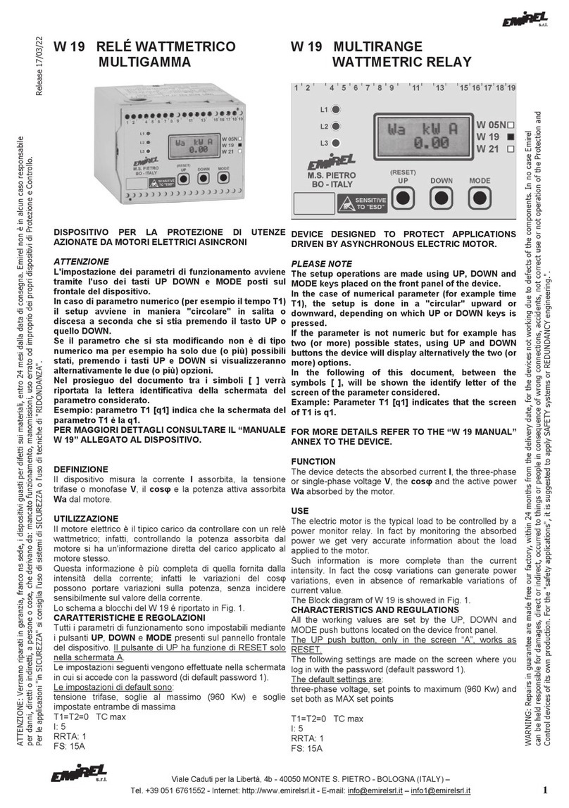
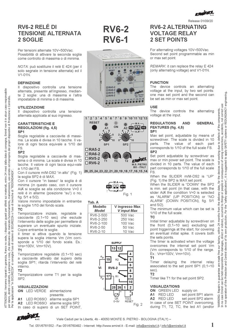
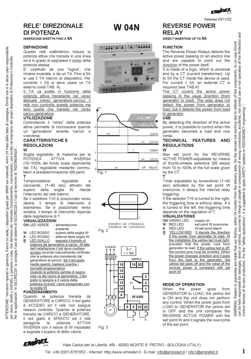
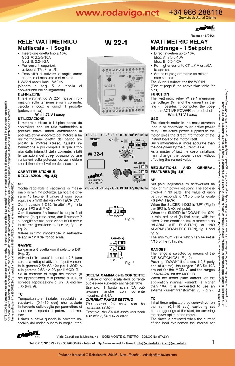
Emirel W 40 User manual

Viale Caduti per la Libertà, 4/B - 40050 MONTE S. PIETRO - BOLOGNA (ITALY)
Tel. +39 (0)51-6761552 - Internet: http://www.emirelsrl.it - E-mail: [email protected] / [email protected] 1
Release 04/11/22
RELE’ DIREZIONALE
DI POTENZA
INSERZIONE DIRETTA FINO A 5A
Il W 40 sostituisce il W 04N (vedere
Tabella Conversione collegamenti a
pag. 5).
DEFINIZIONE
Questo relè wattmetrico misura la
potenza attiva che transita in una linea
ed è in grado di segnalare il verso della
potenza stessa.
E’ costituito da una “logica”, che rima-
ne invariata, e da un TA. Fino a 5A si
usa il TA interno al dispositivo. Per cor-
rente > 5A si deve usare un TA esterno
(vedi TAB. A). Il TA esterno va scelto in
funzione della potenza attiva transitan-
te nel verso abituale (verso generatore-
carico); il relè non controlla questa
potenza ma solo quella che transita nel
verso carico-generatore.
UTILIZZAZIONE
Controllando il “verso” della potenza
attiva permette di riconoscere quando
un “generatore” diventa “carico” o
viceversa.
CARATTERISTICHE E
REGOLAZIONI (Fig. 1)
SP
Soglia regolabile, di massima per la
POTENZA ATTIVA INVERSA (10÷
100% del fondo scala dipendente dal
TA), regolabile mediante commutatori
a predeterminazione (99 parti).
T
Temporizzatore, regolabile a cacciavi-
te, (1÷40 sec) attivato dal supero della
soglia SP, ritarda l’intervento del relè
interno.
VISUALIZZAZIONI
ON LED VERDE : alimentazione
presente.
ALED ROSSO : allarme soglia SP.
In caso di supero del SET POINT,
durante T, il led A lampeggia
velocemente, al termine di T il led A
resta acceso, a LUCE FISSA, se il
supero continua ad essere
presente. Il led A lampeggia a
FREQUENZA BASSA, se si è
attivata la memoria e il supero è
cessato.
RLED GIALLO : segnala il transito di
potenza da generatore a carico.
All’atto dell’installazione il led deve
risultare acceso (avendo natural-
mente verificato che la potenza stia
transitando dal generatore al
carico). Se il led giallo risulta
spento, basterà invertire il collega-
mento ai morsetti amperometrici.
Quando la potenza cambia il verso,
cioè va dal carico al generatore, il
led giallo si spegne e il valore della
“potenza inversa” è presente sul-
l’uscita analogica e viene parago-
nato con la soglia SP.
In caso di I=0 il led giallo lampeggia
W 40
Fig. 1
Fig. 2
REVERSE POWER
RELAY
DIRECT INSERTION UP TO 5A
The W 40 substitutes the W 04N (see
at page 5 the Conversion Table for
pins).
FUNCTION
The Reverse Power Relays detects the
active power passing on an electric line
and are capable to point out the
direction of the power itself.
It is made of a “logic”, which is
universal and by a CT (current
transformer). Up to 5A the CT inside
the device is used. For current > 5A,
an external CT is required (see TAB.A)
The external CT covers the active
power passing in the usual direction
(from generator to load). The relay
does not detect the power from
generator to load, but it detects the
power from load to generator.
USE
By detecting the direction of the active
power, it is possible to control when the
generator becomes a load and vice
versa.
TECHNICAL FEATURES
AND
REGULATIONS (Fig. 1)
SP
Max set point for the REVERSE
ACTIVE POWER adjustable by means
of thumb-wheels selectors (99 steps)
from 10 to 100% of the full scale given
by the CT.
T
Timer adjustable by screwdriver (1÷40
sec) activated by the set point SP
overcoming of the set point SP; it
delays the internal relay triggering.
VISUALIZATIONS
ON GREEN LED : supply on.
ARED LED : set point SP alarm.
In case of the SET POINT
overcoming, during T, the led A
flashes quickly, at the end of T the
led A remains lighted, with FIXED
LIGHT, if the overcoming continues
to be present. The led A flashes at
LOW FREQUENCY, if the memory
started and the overcoming
stopped.
RYELLOW RED : It signals the
direction of the power from
generator to load. At the installation
the yellow led must light, provided
that the power runs from generator
to load. If the yellow led is off, the
connection of the current pins must
be inverted. When the power
changes direction and it goes from
the load to the generator, the
yellow led goes off and the value of
the “reverse power” is on the
analog output and it is compared
with set point SP.
In the case I=0 the yellow led
flashes.
W
AR
NING: Repairs in g
uarant
ee are m
ade fre
e our fac
t
o
ry
,
within
2
4
mont
hs from
the delivery date, for the devices not working due to de
fects of the compone
nts. In no cas
e Em
irel
can be held responsible for damages, direct or indirect, occurred to things or people in consequence of wrong connections, accidents, not correct use or not operation of the Protection and
Control devices of its own production. For the "safety applications", it is suggested to apply SAFETY systems or REDUNDANCY engineering.".
ATTENZIONE:
Verranno r
i
p
a
r
ati in
garan
zia
, franc
o ns sede, i di
spositivi guasti per difetti sui materiali
, entro
2
4
mesi dall
a data di cons
egn
a
. Emirel non è in alcun caso responsabile
per danni, diretti o indiretti, a persone o cose, che derivano da: mancato funzionamento, manomissioni, uso errato od improprio dei propri dispositivi di Protezione e Controllo.
Per le applicazioni "in SICUREZZA" si consiglia l'uso di sistemi di SICUREZZA o l'uso di tecniche di "RIDONDANZA".

Viale Caduti per la Libertà, 4/B - 40050 MONTE S. PIETRO - BOLOGNA (ITALY)
2Tel. +39 (0)51-6761552 - Internet: http://www.emirelsrl.it - E-mail: info@emirelsrl.it / [email protected]
FUNZIONAMENTO
Quando la potenza transita da
GENERATORE a CARICO, il led giallo
è ACCESO ed il relè non esegue
nessun controllo. Quando la potenza
transita da CARICO a GENERATORE,
il led giallo è SPENTO ed il relè
paragona la potenza ATTIVA
INVERSA con il valore di SP
impostato, segnala il supero di detto
valore e l’uscita analogica è attiva.
TARATURA
Fissare il valore di SP tenendo
presente la tabella A, il TA scelto ed il
valore di intervento voluto.
Esempio: si è scelta la gamma di
corrente 10A, quindi il fondo scala della
potenza inversa è 440W (V. TAB. A).
Se si vuole un intervento del SET
POINT a 200W, si fisserà il set point a
45 (440W : 100 = 200W : x
x = 100x200W/440W = 45,4).
RIPRISTINO
Se non si esegue il cavallotto 1-2, la
soglia è a ripristino manuale, mediante
reset sul frontale o apertura del
cavallotto 1-2 o togliendo
l’alimentazione.
Se si esegue il cavallotto 1-2, la soglia
diventa a ripristino automatico.
NOTA 1
In presenza di motori TRIFASE si scon-
siglia di mettere in atto sia la memoriz-
zazione dell’intervento, sia T=0, perché
allo spegnimento del motore le tre fasi
non sono interrotte contemporaneamen-
te dal teleruttore.
Essendo una fase staccata prima delle
altre, per un breve tempo si ha un
supero di potenza sulle altre due fasi,
che può essere memorizzato dal disposi-
tivo. In questi casi è opportuno lasciare
un “piccolo” T1 o adottare altre soluzioni
compatibili con l’applicazione (PLC e
cc
)
.
SICUREZZA INTRINSECA
Il relé interno è normalmente ON e va
OFF in caso di supero della soglia.
INSTALLAZIONE
COLLEGAMENTI ELETTRICI
Collegamenti a vite sul frontale da ese-
guire secondo schemi di fig.3-4(carico
trifase) o fig. 5, 6 (carico monofase).
Per la scelta del TA vedere TAB. A.
(Collegamento a un quadro elettrico
con differenziale e sezionatore). La
lunghezza di ogni collegamento deve
essere < 30m.
ESEMPI DI COLLEGAMENTI
1. TRIFASE It < 5A:
inserzione diretta
Seguire lo schema di fig.3
pin voltmetrici : 19-21-23
pin amperometrici : 14-15
2. TRIFASE It > 5A:
collegamento con TA esterno ../5;
Seguire lo schema di fig. 4
pin voltmetrici : 19-21-23
pin amperometrici : 14-15
Fig. 3
Fig. 4
Fig. 5
Fig. 6
MODE OF OPERATION
When the power goes from
GENERATOR to LOAD, the yellow led
is ON and the unit does not perform
any control. When the power goes from
LOAD to GENERATOR the yellow led
is OFF and the unit compares the
REVERSE ACTIVE POWER with the
set point SP, it signals the overcoming
of the set point and the analog output
is active.
SETTING
Fix the value of SP basing on the
TABLE A for selecting the CT and the
triggering point requested.
Example: the current range 10A is
chosen, so the full scale of the reverse
power is 440W (See TAB. A).
For SET POINT triggering at 200W, the
set point must be set at 45
(440W : 100 = 200W : x
x = 100x200W/440W = 45,4).
RESET
If the link 1-2 is not made, the set point
resets manually, by means of the reset
on the front or opening the jumper 1-2
or removing the power supply.
If the link 1-2 is made, the set point
resets automatically.
REMARK 1
For THREE-PHASE motors, we suggest
not to record the triggering (memory)
and set T=0 at the same time; in fact
when the motor goes off, the three
phases are not disconnected
simultaneously.
One phase being disconnected before, it
procures a short power increase on the
other two. Such overcoming may be
recorded by the device. In such cases it
is suggested to set a very short time (T)
and adopt suitable solutions according to
the applicat
ions (PLC etc).
POSITIVE SAFETY
The internal relay is normally ON and it
turns OFF at the set point overcoming.
INSTALLATION
WIRING DIAGRAMS
Screw connections on the front to be
made as per fig.3-4 (three-phase load)
and fig. 5, 6 (single-phase load).
For selecting the CT, see TAB. A.
(Wiring to an electrical board with a
differential relay and a sectionalizing
switch). The length of every wiring
must be less than 30m.
EXAMPLES OF CONNECTIONS
1. THREEPHASE Ip < 5A:
direct insertion
Follow diagram of fig.3
Voltage pins : 19-21-23
Current pins : 14-15
2. THREEPHASE Ip > 5A:
connection with an external CT ../5
Follow diagram of fig. 4
Voltage pins : 19-21-23
Current pins : 14-15

Viale Caduti per la Libertà, 4/B - 40050 MONTE S. PIETRO - BOLOGNA (ITALY)
Tel. +39 (0)51-6761552 - Internet: http://www.emirelsrl.it - E-mail: [email protected] / [email protected] 3
3. MONOFASE It < 5A:
inserzione diretta
Seguire lo schema di fig. 5
pin voltmetrici : 19-17
pin amperometrici : 14-15
4. MONOFASE It > 5A:
collegamento con TA esterno ../5,
seguire lo schema di fig. 6.
pin voltmetrici : 19-17
pin amperometrici : 14-15
NOTA 2
La fase di cui viene misurata la corrente
(fase AMPEROMETRICA) deve essere
collegata al pin 19. Il collegamento delle
altre due fasi non deve rispettare alcun
vincolo. Per l’eventuale inversione della
rotazione del motore, non utilizzare la
fase amperometrica
.
Per applicare un W 40 occorre
determinare i seguenti due elementi:
1.) tensione del carico (400 Vac ecc.)
2.) I = corrente presente in linea
quando la potenza è massima.
Esempi per illustrare il criterio e le
modalità di definizione del fondo scala.
a) Se I é minore di 5A si può usare l’in-
serzione diretta (v. schemi di fig.3 e 5).
b) Se I é maggiore di 5A si deve usare
un riduttore di corrente (TA) …/5
(schema di fig.4 e 6).
ESEMPIO A): carico trifase V=400Vac,
corrente ≤ 5A (Fig. 3), nella TAB. A
nella prima riga della colonna FS(A)
troviamo 5A e nella colonna POTENZA
DIRETTA si trova 3,5kW e nella prima
riga della colonna POTENZA INVER-
SA si trova 220W. I 100 gradini del
SET POINT avranno un “peso” di 2,2W
ciascuno.
ESEMPIO B): carico trifase V=400Vac,
corrente ≤ 20A (Fig. 4), nella TAB. A si
sceglie la riga con FS(A)=25A, che
sarà realizzato con l’uso di un TA 50/5
PRESTAZIONE > 5VA, CLASSE 0,5,
facendo passare il filo di corrente 2
volte entro il foro del TA (N.=2 nella
terza colonna). La POTENZA DIRET-
TA massima, associata a 25A, sarà
17,5kW. La POTENZA INVERSA
massima sarà 1100W. I 100 gradini del
SET POINT avranno un peso di 11W
ciascuno.
INGRESSI
Pin voltmetrici: 23-21-19.
Ring = 800 kW
Si veda NOTA 4.
Pin amperometrici: 15-14.
Nessuna sequenza da rispettare.
La massima tensione trifase è 415Vac.
Per tensioni maggiori si può utilizzare:
M 08: Resistenze di caduta + TA per
garantire isolamento.
USCITA
5A(NA) 3A(NC)-230 Vac carico resisti-
vo
R1 5-6 NC Dispositivo non
5-4 NA alimentato o in allarme
ATTENZIONE
Nel caso di carico monofase,
seguire i collegamenti di fig. 5/6. Per
scegliere il codice prodotto, fare
attenzione alla colonna “TENSIONE
DEL CARICO” di COME ORDINARE.
Esempio: il modello A è adatto per
carico trifase da 400V oppure per
carico monofase da 230V; cambia lo
schema di collegamento da
effettuare.
PAY ATTENTION
In the applications with single phase
motor, the electrical connections to
be effected are those of fig. 5/6. For
the correct identification of the
product code, pay attention to the
column “LOAD VOLTAGE” in the HOW
TO ORDER diagram.
Example: the model A is suitable for
3phase load 400V or for 1phase
load 230V but the electrical
connections to be effected follow a
diffe
rent sche
m
e.
NOTA 3
La grandezza del TA esterno va scelta in
funzione della CORRENTE presente in
linea quando la corrente é massima.
REMARK 3
The size of the external CT is chosen
basing on the maximum CURRENT in
line.
NOTA: Il TA esterno dovrebbe avere
una PRESTAZIONE ³5VA per
rispettare il FATTORE DI POTENZA.
REMARK: The external CT must have
the BURDEN
³
5VA to not modify the
POWER FACTOR.
NOTA 4
Per un miglior utilizzo del relè wattme-
trico, si consiglia di scegliere un fondo
scala di poco superiore al valore
massimo di I.
REMARK 4
For the best working of W 40, the current
full scale must be slightly greater than
the
max value of I.
NOTA 5
Si consiglia vivamente l’uso di gruppi RC
sulle bobine dei teleruttori.
REMARK 5
The application of RC groups on the
contactors coils is highly recommended.
Nota generale: Negli schemi di
collegamento non sono riportati i fusibili
sulle alimentazioni e sugli ingressi
voltmetrici. I collegamenti elettrici devono
essere eseguiti a dispositivo e quadro
elettrico spenti.
General remark: The wiring diagrams
do not show the fuses installed on the
supply and on the voltmetric inputs.
The electric wirings must be realized with
device and electrical panel in off
co
ndi
tion.
3. SINGLE PHASE Ip< 5A:
direct insertion
Follow diagram of fig. 5
Voltage pins : 19-17
Current pins : 14-15
4. SINGLE PHASE It > 5A:
connection with an external CT ../5,
follow diagram of fig. 6.
Voltage pins : 19-17
Current pins : 14-15
REMARK 2
The wire passing through the CT
(AMPEROMETRIC phase) must be
connected to the pin 19 while the other
two phases are connected without any
order. For the possible inversion of the
motor rotation, the amperometric phase
must not be used
.
For the application of W 40 the follo-
wing elements are necessary:
1.) Load voltage (400 Vac etc.)
2.) I = current present on the line
when the power is at the
maximum.
Examples for the full scale selection:
a) If I is lower than 5A the device is by
direct insertion connected (fig. 3 and 5)
b) If I is higher than 5A it is requested a
current transformer (CT) .../5 (fig.4 and
6).
EXAMPLE A): three-phase load
V=400Vac, current ≤ 5A (Fig. 3), in the
TAB. A in the first line of the column
FS(A) 5A is showed and in the column
DIRECT POWER 3,5kW is showed
and in the first line of the column
REVERSE POWER 220W is showed.
The 100 steps of the SET POINT will
have a “weight” of 2,2W each one.
EXAMPLE B): three-phase load
V=400Vac, current ≤ 20A (Fig. 4), in
the TAB. A the line with FS(A)=25A is
chosen, this FS will be obtained using
a CT 50/5, BURDEN > 5VA, CLASS
0,5, by passing the current wire twice
through the hole of the CT (N.=2 in the
third column). The maximum DIRECT
POWER for 25A will be 17,5kW. The
maximum REVERSE POWER will be
1100W. The 100 steps of the SET
POINT will have a “weight” of 11W
each one.
INPUTS
Voltage pins: 23-21-19.
Input Resistance = 800 kW
See REMARK 4.
Current pins: 15-14.
No specific order to be followed.
The maximum three-phase voltage is
415 Vac. For higher voltages, it is
requested the application of:
M 08: Three-phase drop resistances +
CT for insulation.
OUTPUT RELAY
5A(NO) 3A(NC)-230 Vac resistive load
R1 5-6 NC Device not supplied
5-4 NO or in alarm

Viale Caduti per la Libertà, 4/B - 40050 MONTE S. PIETRO - BOLOGNA (ITALY)
4Tel. +39 (0)51-6761552 - Internet: http://www.emirelsrl.it - E-mail: info@emirelsrl.it / [email protected]
USCITA ANALOGICA
L’uscita analogica è attiva (0÷5V)
quando la potenza va da carico a
generatore. Quando il verso è
generatore-carico l’uscita analogica è
0.
Pin 26(+) e 25.
0÷5Vdc IMAX =1mA
Il valore teorico della potenza di “fondo
scala” riportato nella tabella A permette
di dare il “PESO” ai Volt dell’Uscita
Analogica.
La tensione 0÷5Vdc presente sui
terminali 25-26 può essere collegata
ad un voltmetro “a rapporto” come il
DVD 08, per visualizzare il valore
istantaneo della POTENZA INVERSA.
Esempio: nel caso della prima riga
della TAB. A, i 5V
corrispondono a 220W,
quindi ogni Volt corrisponde a
220W/5V=44W.
Se sull’uscita analogica sono
presenti 1,8V, si dovrà tarare
il DVD 08 per leggere
1,8x44=79,2W.
ISOLAMENTO
Separazione galvanica tramite il
trasformatore di alimentazione e TA
interno.
ALIMENTAZIONE: (monotensione)
2VA 50-60Hz - tolleranza ±10%
13-12: 24Vac oppure 48Vac oppure
115Vac o 230Vac
DIMENSIONI /CUSTODIA
70x75x110mm per DIN
E 405B Protezione frontale trasparente
piombabile (a richiesta).
TEMP. DI FUNZIONAMENTO: 0÷70°C
PESO: Kg 0,550
COLORE: grigio, simile al RAL 35.
GAMME DI LAVORO
Inserzione diretta per 5A.
Per valori superiori a 5A si applica un
TA esterno …/5 del valore richiesto,
come indicato in TAB. A.
Per la pulizia usare un panno imbevuto di
detergenti privi di: Alcool denaturato,
Benzene, Alcool isopropilico.
For cleaning use a cloth soaked with
detergents without: Denatured Alcohol,
Benzene, Isopropyl alcohol.
DVD 08
Legenda
TAB. A
FS (A) : Fondo Scala della Corrente
TA : Riduttore di Corrente
Esterno
N : Numero Passaggi del Filo
entro il TA esterno (fig. 2).
Leg
end
TAB
.
A
F
S (A) : Full S
cale
of the
C
urrent
CT : External Current
Transformer
.
N : Number of the Wire
Windings through the
e
xt
ern
al
C
T
(fig.
2)
.
COMPATIBILITA' ELETTRO
MAGNETICA
Electromagnetic compatibility
CEI
-
EN
61326
-
1
“BASSA TENSIONE” - LVD
LVD – “LOW VOLTAGE”
CEI-EN 61010-1
ANALOG OUTPUT
The analog output is active (0÷5V)
when the power goes from load to
generator. When the direction is
generator-load the analog output is 0.
Pin 26(+) and 25.
0÷5Vdc IMAX =1mA
The theoretical value of “full scale”
power shown in the table A allows to
give the “WEIGHT” to the Analog
Output Volts.
The voltage 0÷5Vdc on the pins 25-26
can be connected to a voltmeter with
calibration of the reading such as the
DVD 08, to display the instantaneous
value of the REVERSE POWER.
Example: in the case of the first line of
the TAB. A, 5V corresponds
to 220W, so each Volt
corresponds to
220W/5V=44W.
If there are 1,8V on the
analog output, the DVD 08
must be calibrated to read
1,8x44=79,2W.
INSULATION
Galvanic separation through the power
transformer and internal CT.
SUPPLY: (single voltage)
2VA 50-60 Hz - tolerance ±10%
13-12: 24Vac or 48Vac or 115Vac or
230 Vac
DIMENSIONS / CASE
70x75x110 mm for DIN rail.
E 405B transparent front cover for tight
closure (on request).
WORKING TEMPERATURE: 0÷70°C
WEIGHT: Kg 0,550
COLOUR: grey, similar to RAL 35.
RANGES
Direct insertion up to 5A.
For values higher than 5A, an external
CT …/5 of the requested value is
applied, following TAB. A.
POTENZA (Power)
VALORI TEORICI (Theoretical Values)
(COSφ=1)
(400 Vac TRIFASE / 3Phase)
POTENZA (Power)
VALORI TEORICI (Theoretical Values)
(COSφ=1)
(230 Vac MONOFASE / 1Phase)
TAB. A DIRETTA (Direct) INVERSA (Reverse) DIRETTA (Direct) INVERSA (Reverse)
FS (A) TA
(
CT
)
N. da generatore a carico
(
f
rom gener
at
or to l
oa
d
)
da carico a generatore
(
f
rom load to generator
)
da generatore a carico
(
from generator to load
)
da carico a generatore
(
from l
oad
to generator
)
5 - - 3,5 kW 220 W 1,16 kW 72 W
10 50/5
5 7 kW 440 W 2,33 kW 146 W
12,5 50/5
4 8,75 kW 550 W 2,91 kW 183 W
16,6 50/5
3 11,6 kW 725 W 3,86 kW 240 W
25,0 50/5
2 17,5 kW 1,1 kW 5,83 kW 360 W
33,0 100/5
3 23,1 kW 1,4 kW 7,7 kW 460 W
50,0 50/5
1 35 kW 2,18 kW 11,6 kW 726 W
75 150/5
2 52,5 kW 3,28 kW 17,5 kW 1,1 kW
100 100/5
1 70 kW 4,4 kW 23,3 kW 1,46 kW
[W = 1,73 x 400 x I] [W = 230 x I]

Viale Caduti per la Libertà, 4/B - 40050 MONTE S. PIETRO - BOLOGNA (ITALY)
Tel. +39 (0)51-6761552 - Internet: http://www.emirelsrl.it - E-mail: [email protected] / [email protected] 5
TABELLA DI CONVERSIONE COLLEGAMENTI
(Conversion Table for Pins)
PIN W 04N PIN W 40
15
16
MORSETTI CORRENTE (Current Terminal Blocks)
15
14
MORSETTI CORRENTE (Current Terminal Blocks)
14 L3 19 L3
12 L2 21 L2
10 L1 23 L1
4 N(NEUTRO) (Neutral) 17 N(NEUTRO) (Neutral)
19 ALIMENTAZIONE (Supply) 12 ALIMENTAZIONE (Supply)
20 ALIMENTAZIONE (Supply) 13 ALIMENTAZIONE (Supply)
23 0V 17 0V
5 M 2 RESET
22 RES
3 R W 6 R R
2 C W 5 C R
1 L W 4 L R
8 0V 25 0V
/ / 26 USCITA ANALOGICA (Analog Output)
In TAB. A, il rapporto tra POTENZA DIRETTA e POTENZA INVERSA è di circa 16.
A richiesta il valore del rapporto può essere diverso, ad es. 1, …, 5 ecc…
In TAB. A, the ratio between the DIRECT POWER and REVERSE POWER is about 16.
On request the value of the ratio may be different, for instance 1, …, 5 etc…
In TAB. A sono riportate le GAMME di CORRENTE e di POTENZA ATTIVA che sono possibili con la rete trifase alimentata
a 400 VAC. (The TAB. A shows the possible RANGES of CURRENT and of ACTIVE POWER with the three-phase mains
supplied at 400 VAC.)
·Se la tensione trifase = 230 VAC, i valori di potenza vanno divisi per 1,73 = 400/230
If the three-phase voltage = 230 VAC, the power values must be divided by 1,73 = 400/230
·Se la tensione trifase = 415 VAC, i valori di potenza vanno moltiplicati per 1,03 = 415/400
If the three-phase voltage = 415 VAC, the power values must be multiplied by 1,03 = 415/400
·Per la tensione MONOFASE = 230V, i valori di potenza sono stati divisi per 3 rispetto alla tabella 400 VAC trifase.
For the ONE-PHASE voltage = 230V, the power values have been divided by 3 compared to the 400 VAC three-
phase table.
NOTA 0
Nelle figure i CONTATTI dei relè interni sono riportati nella condizione di relè
interno OFF (DISPOSITIVO non alimentato).
REMARK 0
In the figures the CONTACTS of the internal relays are shown with internal relay
in OFF condition (DEVICE not supplied).
Table of contents
Other Emirel Relay manuals
