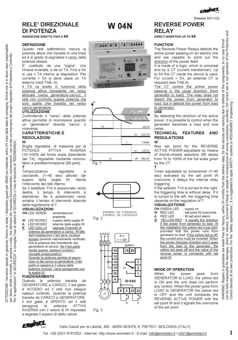
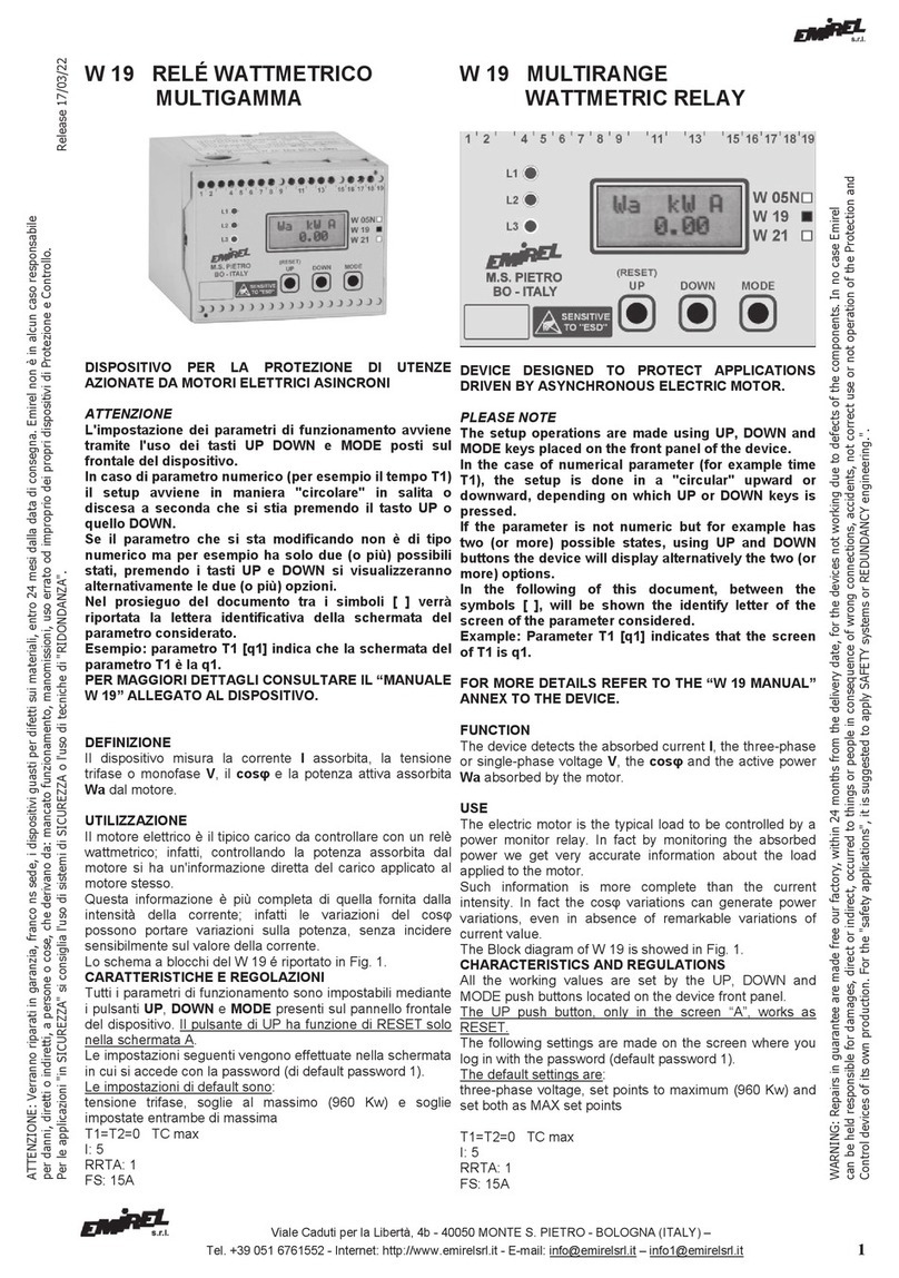
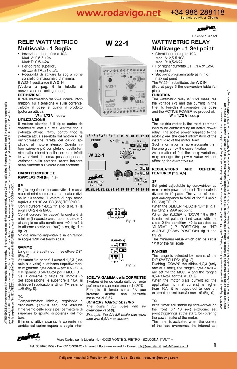
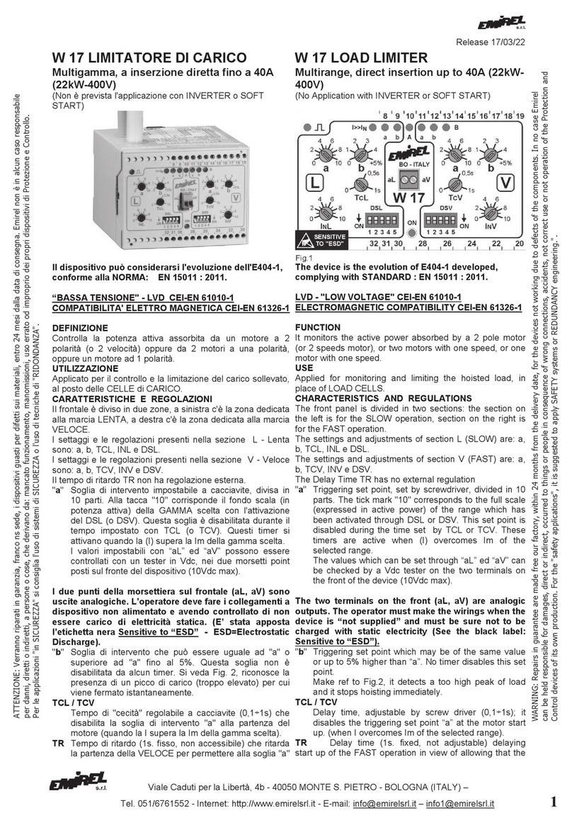
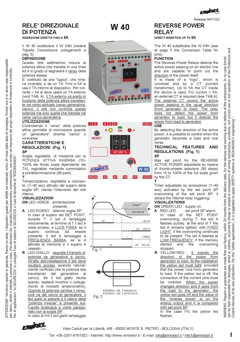
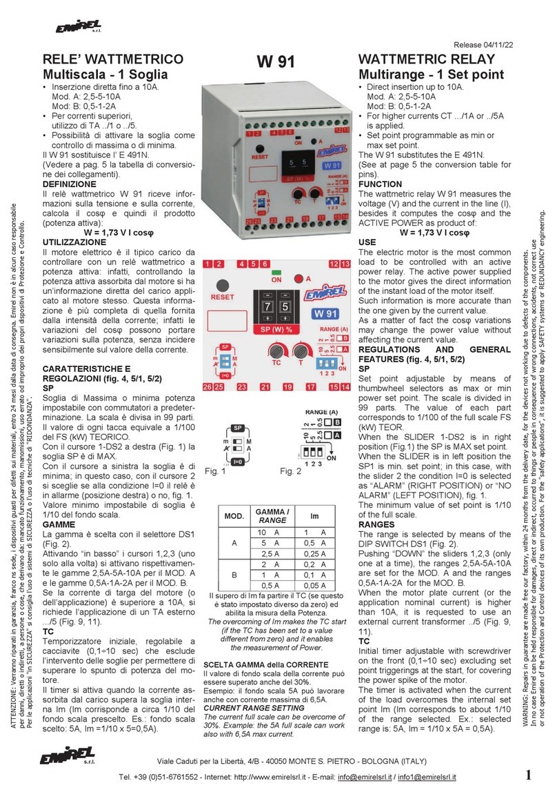
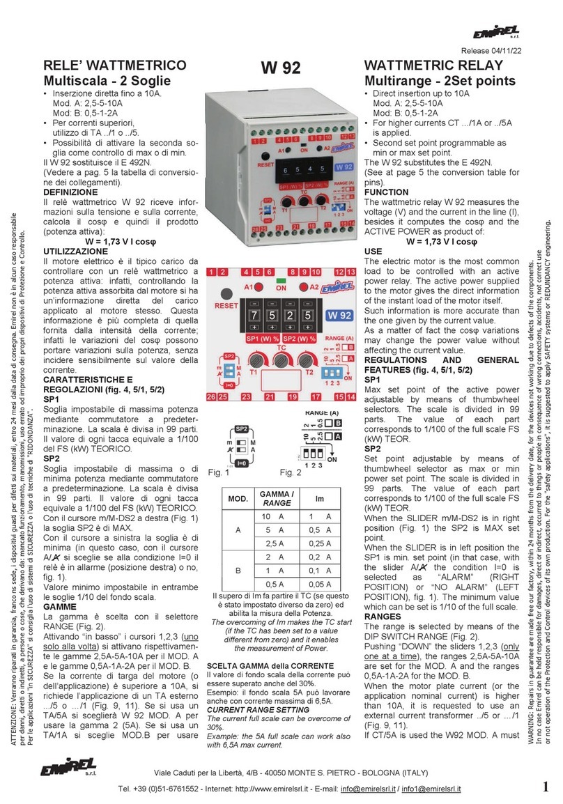
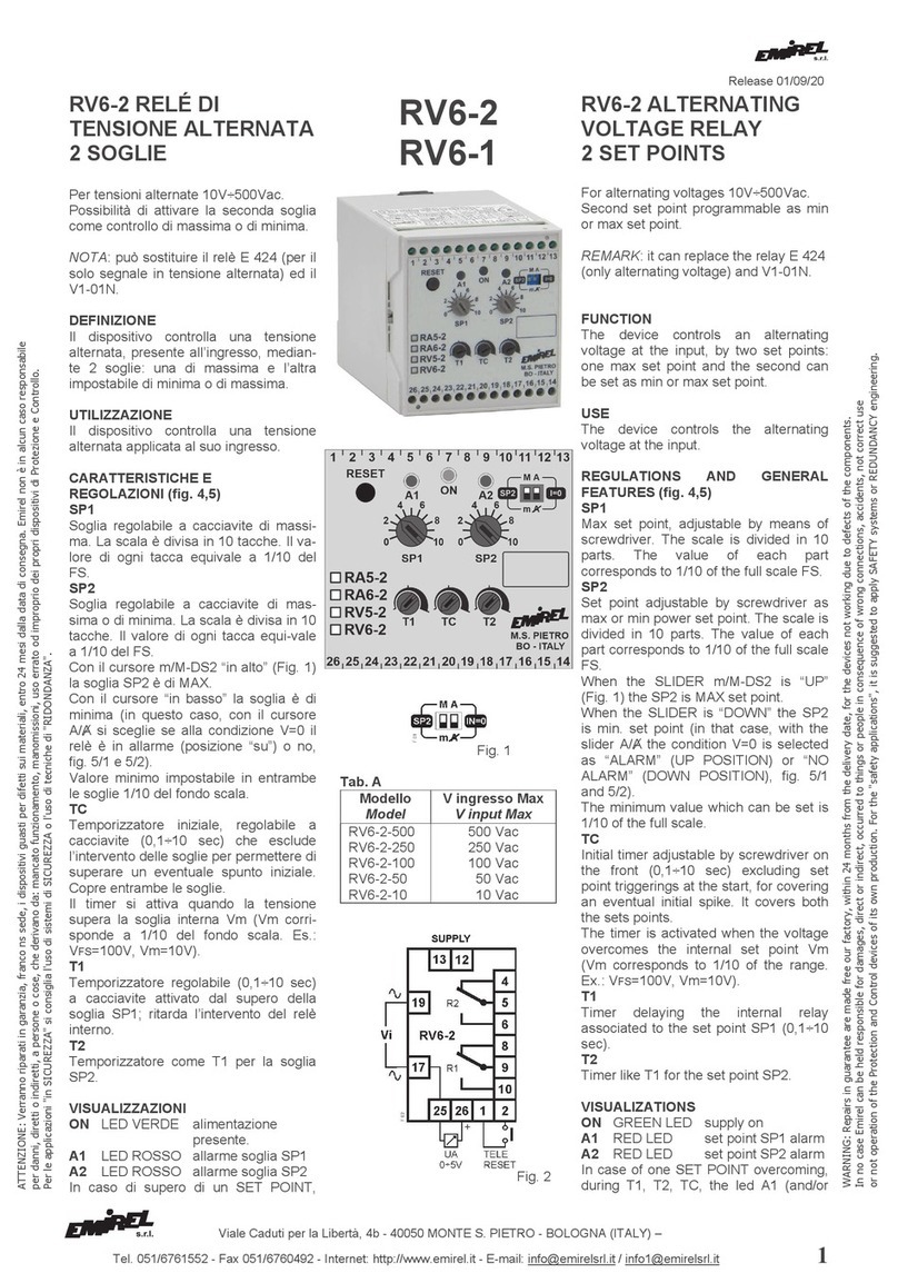
Emirel W 55 User manual

Release 21/04/23
Viale Caduti per la Libertà, 4/B - 40050 MONTE S. PIETRO - BOLOGNA (ITALY)
Tel. +39 (0)51-6761552 - Internet: http://www.emirelsrl.it - E-mail: [email protected] / [email protected] 1
W 55 RELÉ WATTMETRICO
CONTROLLO COCLEE
INSERZIONE DIRETTA FINO A 5A POI TA ESTERNO
Il W 55 sostituisce il W 05N e il W 05A cambiando i
collegamenti (Pag. 8).
ATTENZIONE
L'impostazione dei parametri di funzionamento avviene
tramite l'uso dei tasti UP DOWN e MODE posti sul
frontale del dispositivo.
In caso di parametro numerico (per esempio il tempo t1)
il setup avviene in maniera "circolare" in salita o
discesa a seconda che si stia premendo il tasto UP o
quello DOWN.
Se il parametro che si sta modificando non è di tipo
numerico ma per esempio ha solo due (o più) possibili
stati, premendo i tasti UP e DOWN si visualizzeranno
alternativamente le due (o più) opzioni.
PER MAGGIORI DETTAGLI CONSULTARE LA PAG. 8.
DEFINIZIONE
É un relè wattmetrico di massima, con comando RUN e
REVERSE per permettere alla macchina di superare un
inceppamento momentaneo.
UTILIZZAZIONE
Trova principale applicazione nel controllo delle coclee.
Queste sono utilizzate principalmente per il trasporto di
materie solide (plastica, trucioli di lavorazione meccaniche
ecc.) dove un eventuale corpo estraneo o un intasamento
può procurare danni ingenti al sistema meccanico.
Il W 55 permette di controllare il sistema meccanico motore-
riduttore-coclea riducendo al minimo le possibilità di guasto.
Lo schema a blocchi del W 55 è riportato in fig. 1.
CARATTERISTICHE E REGOLAZIONI
Tutti i parametri di funzionamento sono impostabili mediante
i pulsanti UP, DOWN e MODE presenti sul pannello frontale
del dispositivo. I pulsanti di UP e DOWN hanno funzione di
RESET solo nella schermata A.
Le impostazioni di seguito sono accessibili entrando nel
menù nella schermata D e impostando la password (valore
di collaudo: 1).
In caso di password corretta alla pressione di MODE si
andrà alla schermata [SET VN].
In caso di password errata alla pressione di MODE si andrà
alla schermata [A].
S1
Soglia di intervento di massima (visibile sul display LCD)
impostabile con i tasti UP e DOWN.
W 55 WATTMETRIC RELAY
FOR CONTROL OF SCREW FEEDER
(ARCHIMEDEAN SCREW)
DIRECT INSERTION UP TO 5A THEN EXTERNAL CT
W 55 replaces W 05N and W 05A changing the electrical
connections (Pag. 8).
PAY ATTENTION
The push buttons “UP” and “DOWN” on the front are
used for select the value of a parameter.
If the parameter is “numerical” (ex. The t1 time) the
value change in a circular way ahead or back.
If the parameter has only 2 values the 2 values are
alternately shown.
SEE PAG. 8.
FUNCTION
W 55 is a wattmetric relay with one max set point along with
RUN and REVERSE commands for enabling a machine to
overcome a short-lived clogging.
USE
It is mainly employed for the control of the worm conveyors.
They are employed for the transport of solid stuffs (plastic,
chips handling etc.) where an external body or an
unexpected clogging could procure high damages to the
mechanical system.
With W 55 it is possible to control the mechanical system
motor – reduction unit – worm conveyor in order to reduce
the possibility of a break down.
In fig. 1 there is the block diagram of W 55.
TECHNICAL FEATURES AND REGULATIONS
All parameters are set by means of push-buttons UP,
DOWN, MODE on the front. UP + DOWN push-buttons
make the reset only in the “A” screen.
For the settings you must enter the menu in the D screen
and setting the password (initial value = 1).
If the password is correct, pressing MODE, the menu pass to
[SET VN] screen.
If the password is not correct, pressing MODE, the menu
pass to [A] screen.
S1
MAX set point (visible on LCD display) the value is setting by
means of “UP” and “DOWN”.
ATTENZIONE:
V
e
rranno ri
parati in
garanz
ia, franc
o ns sede, i dispo
sitivi guasti pe
r d
ifetti sui mater
ial
i, entro
2
4
m
esi dalla data di c
onsegna.
Emirel no
n
è in a
lcun c
a
so re
spons
ab
ile
per danni, diretti o indiretti, a persone o cose, che derivano da: mancato funzionamento, manomissioni, uso errato od improprio dei propri dispositivi di Protezione e Controllo.
Per le applicazioni "in SICUREZZA" si consiglia l'uso di sistemi di SICUREZZA o l'uso di tecniche di "RIDONDANZA".
WARNING: Repairs in g
uaran
t
ee are made free our factory,
within
2
4
months
fro
m the
delivery da
t
e, for
the devices not
working
d
ue to defects of t
he components. In no case Emirel
can be held responsible for damages, direct or indirect, occurred to things or people in consequence of wrong connections, accidents, not correct use or not operation of the Protection and
Control devices of its own production. For the "safety applications", it is suggested to apply SAFETY systems or REDUNDANCY engineering.".

Viale Caduti per la Libertà, 4/B - 40050 MONTE S. PIETRO - BOLOGNA (ITALY)
Tel. +39 (0)51-6761552 - Internet: http://www.emirelsrl.it - E-mail: [email protected] / [email protected] 2
Il valore varia da 0,1 a 550kW (vedere TAB. 1).
La soglia S1 è collegata ai relè A (RUN) e B (REV);
l’intervento dei relè A e B è ritardato dei tempi t1 e tC.
t1
Temporizzazione regolabile da 0,1 a 4 sec.
Ritarda l'intervento dei relè di allarme A e B quando avviene
il supero della soglia S1.
tR
Temporizzatore, regolabile (1÷15 sec.); fissa la durata del
funzionamento reverse.
tC
Temporizzatore iniziale, regolabile (0,1÷6 sec.); esclude
l’intervento della soglia per superare lo spunto di corrente
del motore.
Il timer si attiva quando la corrente assorbita dal carico
supera la soglia interna Im (Im corrisponde a 1/10 del fondo
scala prescelto).
RR (V. TAB. 1)
Rapporto di riduzione del TA.
E’ variabile da 1 a 160.
In Versione Standard massimo TA 800/5; RRTA=160.
Il parametro RR è il rapporto tra la corrente del primario Ip e
la corrente Is del secondario del TA esterno.
In caso di inserzione diretta, RR=1.
Agendo sui pulsanti UP o DOWN sarà possibile impostare il
valore desiderato.
Per l'impostazione del valore del parametro RR consultare la
tabella 1.
N (V. TAB. 1)
È il numero di passaggi eventualmente fatti nel TA esterno
N: 1÷5
In figura 2 è mostrato il caso di 2 passaggi nel TA esterno.
GAMME
Dalla TAB. 1 si ricavano le possibili GAMME della corrente e
della potenza ATTIVA (con VD= 400Vac).
Per IP> 5 è previsto l’uso del TA esterno …/5 ed il filo che
porta la corrente farà N passaggi entro il foro del TA (Fig. 2).
The value varies from 0,1 to 550kW (see TAB. 1).
The S1 set point is related with “A” (RUN) and “B” (REV)
relays, the triggering of A and B relays is delayed of t1 and
tC times.
t1
Timer (0,1 ÷ 4s). It delays the A and B relays when S1 is
overcome.
tR
Timer (1 ÷ 5s). It selects the length of the “REVERSE”
MODE.
tC
Timer (0,1 ÷ 6s). It excludes the set point triggering at the
start of the current, bypassing the power spike. It is activated
when the current exceeds the internal set point Im (Im, see
TAB. A is 1/10 of the full scale value of the current).
RR (See TAB. 1)
Reduction ratio of CT (1÷160). It is the ratio between the
primary current and secondary current Ip/Is of the external
CT.
For direct insertion, RR=1.
UP and DOWN are used for fixing the right value (See TAB.
1).
Fig. 2
N (See TAB. 1)
It is the number of the possible wire windings inside the
external CT
N: 1÷5
Fig. 2 shows an example with 2 passages in the external
CT.
RANGES
From TAB. 1 the possible RANGES of the current and of the
ACTIVE power are obtained (with VD= 400Vac).
For IP> 5, the external CT .../5 must be used and N
windings of the current wire will be carried out inside the
hole of the CT (Fig. 2).
Fig. 1

Viale Caduti per la Libertà, 4/B - 40050 MONTE S. PIETRO - BOLOGNA (ITALY)
Tel. +39 (0)51-6761552 - Internet: http://www.emirelsrl.it - E-mail: [email protected] / [email protected] 3
VN
Tensione nominale di riferimento del dispositivo.
Per sistemi trifasi VN=400Vac (valore di default).
Per tensioni trifasi maggiori di 500Vac è necessario usare il
dispositivo M 08.
VNvaria tra 400 e 700V.
Esempio:
Tensione trifase ≤ 500Vac VN=400Vac M 08: NO
Tensione trifase di 600Vac VN=600Vac M 08: SI
PWD
Impostazione password da 1 a 999 (default:1).
VISUALIZZAZIONI
L1 ROSSO Visualizza lo stato di RUN.
E’ acceso se il relè A è ON.
L2 ROSSO Visualizza lo stato di REV.
E’ acceso se il relè B è ON.
L3 ROSSO Visualizza lo stato di supero (lampeggia) e
lo stato di blocco (fisso).
L4 ROSSO Indica lo stato di ALLARME e l’attivazione
del relè RC di segnalazione.
VN
Rated voltage of reference of the device.
For three-phase systems VN=400Vac (default value).
For three-phase voltages greater than 500Vac, the device M
08 must be used.
VNvaries from 400 to 700V.
Example:
Three-phase voltage ≤ 500Vac VN=400Vac M 08: NO
Three-phase voltage of 600Vac VN=600Vac M 08: YES
PWD
Password value (1÷999) default = 1.
VISUALIZATIONS
L1 (RED) It is ON if the A (RUN) relay is ON.
L2 (RED) It is ON if the B (REVERSE) relay is ON.
L3 (RED) It is blanking when the set point is
overcome. It is ON for fixed block
(alarm).
L4 (RED) It indicates the ALARM condition and the
activation of the signaling relay RC.
TAB. 1 TRIFASE / THREE-PHASE 400 VAC
IP
(A)
N
Numero
di
Passaggi
nel TA esterno
WINDINGS
NUMBER
THROUGH
THE EXTERNAL CT
TA (EST.)
(EXT.) CT
CL.=0,5
PREST. > 5VA
B
U
RD
E
N
>
5V
A
Wa
TEORICA
THEORETICAL Wa
(COSφ=1) (kW)
K = PESO DI
1V
DELL’USCITA
ANALOGICA
(kW/V)
K = ANALOG
OUTPUT 1V WEIGHT
(kW/V)
TA
CT
RR Wa DIRETTA
DIRECT Wa
5
0
-
1
3,5
0,7kW
10
5
50/
5
10
7
1,4kW
12,5
4
50/5
10
8,75
1,75kW
1
6,6
3
50/
5
10
11,6
2,
32kW
25
2
50/5
10
17,5
3,5kW
33
3
10
0/5
20
23,1
4,62kW
50
1
50/5
10
35
7kW
75
2
1
50
/5
3
0
52,5
10,5kW
1
0
0
1
100/5
20
70
14kW
200
1
200
/5
40
140
28kW
…
…
…
…
…
…
800
1
800
/
5
1
60
553
110,6kW
LEGENDA:
IP (A): è il valore del FONDO SCALA delle GAMME della corrente.
N: numero dei “passaggi” del filo di corrente nei TA, per adeguarsi ai vari TA. È uguale ad 1 nelle due gamme senza TA esterno e quando il
valore di IPè uguale alla corrente massima del TA (50, 100 ecc…).
TA: trasformatore di corrente, esterno al W 55, (Vedere Fig. 2 e 6).
RR: rapporto fra la corrente massima primaria e la corrente secondaria del TA (Es. TA 50/5 ha IP=50A, IS=5A quindi 50A/5A RR=10).
Il valore 1 per la GAMMA senza TA esterno è dovuto ad esigenze del programma del microprocessore.
Wa: valore teorico della Potenza Attiva.
K: è il “peso”, in kW, di 1V della tensione dell’uscita analogica: esempio, se nella GAMMA IP=10A, si leggono 2V sull’USCITA ANALOGICA,
questi rappresentano 2x1,4kW=2,8kW.
LEGEND:
IP (A): FULL SCALE value of the current RANGES.
N: number of the current wire “passages” through the CTs, to adjust to the various CTs. It is equal to 1 in the two ranges without external CT and
when the IPvalue is equal to the CT maximum current (50, 100 etc…).
CT: current transformer, external to the W 55, (See Fig. 2 and 6).
RR: ratio between the primary maximum current and the secondary current of the CT (Ex. CT 50/5 has IP=50A, IS=5A so 50A/5A RR=10).
The value 1 for the RANGE without external CT is due to requirements of the microprocessor program.
Wa: theoretical value of the Active Power.
K: “weight”, in kW, of 1V of the analog output voltage: example, if in the RANGE IP=10A, 2V on the ANALOG OUTPUT are read, these 2V
represent
2x1,4kW=
2,8kW.

Viale Caduti per la Libertà, 4/B - 40050 MONTE S. PIETRO - BOLOGNA (ITALY)
Tel. +39 (0)51-6761552 - Internet: http://www.emirelsrl.it - E-mail: [email protected] / [email protected] 4
Le PAUSE fra RUN e REV sono visualizzate da L1 e L3
accesi. Le PAUSE fra REV e RUN sono visualizzate da L2
lampeggiante.
Le fasi del ciclo 1,2…5 sono indicate nel display LCD.
DISPLAY LCD 2x8 RETROILLUMINATO
Sul display compaiono le grandezze misurate:
- Potenza attiva istantanea Wa(kW)
- Fase di funzionamento
- Ecc.. ecc..
FUNZIONAMENTO
I grafici di Fig. 3 e 4 illustrano il funzionamento del W 55 in
funzione del valore della soglia.
Il dispositivo misura la potenza attiva assorbita dal motore e
la confronta con il valore di riferimento impostato con SET
POINT. Quando la potenza assorbita è al di sotto del valore
impostato, il relé interno RUN è ON ed il relé REV è OFF;
vedere fig. 5 o 6. Se la potenza assorbita supera il valore
impostato con SET POINT, per un periodo superiore al
tempo impostato con il timer t1, il relé RUN va OFF ed il
motore si arresta per circa 3 sec, quindi si rieccita, ma
contemporaneamente si eccita anche il relé REV, per cui il
motore funzionerà in REVERSE per un periodo imposto con
il temporizzatore tR (1÷15 sec) (Fig. 1).
Al termine di tR, entrambi i relé diseccitano ed il motore si
arresta per circa 3 sec, quindi si rieccita RUN ed il motore
riparte in AVANTI.
Questo ciclo automatico é ripetuto fino a 4 volte; alla quinta il
relé RUN va a OFF dopo t1 (BLOCCO) (fig. 3) ad indicare la
necessità dell’intervento dell’operatore, per eliminare la
causa che genera il sovraccarico.
I cicli di RIPARTENZA vengono contati da un contatore
interno e visualizzati sullo schermo LCD. Se l’operazione di
REVERSE ha successo, e non si presenterà un
sovraccarico nella ripartenza successiva, dopo circa 20 sec,
il contatore si resetterà e si tornerà a RUN 1 in [A].
Se durante il funzionamento REVERSE si presenta ancora
la condizione di supero della soglia (coclea bloccata in
entrambi i sensi di rotazione) il dispositivo va in BLOCCO
senza completare il ciclo dei quattro tentativi (fig. 4).
Il LED 4 e il relè RC (pin 7-8) vanno ON quando il dispositivo
va in ALLARME o durante una fase di reverse o dopo un
allarme di fine ciclo.
TARATURA
SET POINT S1
Per regolare il SET POINT si può scegliere tra diverse
modalità:
1) Fissare il valore S1 tenendo presente la Tabella 1, il TA
scelto ed il valore di intervento voluto.
Es.: con I=7,5 A di range, intervento richiesto a 3kW:
regolare S1 a 3,0 kW.
2) Regolare, dopo aver visualizzato dal display il valore di
potenza di lavoro della macchina, la soglia di conseguenza.
3) Portare SET POINT e tC al massimo, t1 al minimo. Con il
motore acceso e la macchina “caricata”, abbassare la
regolazione di SET POINT fino ad avere l’accensione del led
L3 e l’intervento del dispositivo.
A questo valore di soglia si dovranno applicare delle
correzioni che tengano conto delle condizioni operative finali
della macchina, della temperatura, dell’invecchiamento ecc.
Spegnere il motore e riaccendere varie volte, riducendo ogni
volta il tC fino a trovare il valore per cui si ha subito
l’intervento. A questo valore si dovranno apportare delle
correzioni per le stesse considerazioni fatte per la
regolazione di SET POINT. Aumentare opportunamente il t1
The conditions of PAUSE between RUN and REV are
visualized with L1 and L3 ON. The condition of PAUSE
between REV and RUN are visualized with L2 blanking.
The cycle phases 1,2…5 are indicated in the LCD display.
LCD DISPLAY 2x8 BACKLIGHTED
On the screen the following values will appear:
- Active power of the moment Wa(kW)
- Operation phase
- Etc.. etc..
MODE OF OPERATION
Fig. 3 and Fig. 4 show the operation of the W 55 depending
on the set point value.
The device measures the active power of a motor and it
compares it with the reference value set by means of SET
POINT.
When the power is below the set value, the internal relay
RUN is ON and the relay REV is OFF; see fig. 5 or 6.
When the power remains above the values set by SET
POINT, for longer period than the value set by timer t1, the
relay RUN goes OFF and it stops the motor for about 3 secs;
then it starts again, and simultaneously the relay REV goes
ON, and the motor goes on REVERSE running for the period
tR (1÷15 sec) (Fig. 1).
At the end of the period tR, both the two relays go OFF and
the motor stops for about 3 secs. Successively RUN goes
ON and the motor runs FORWARD.
Such cycle automatically repeats up to 4 times; at the 5th
repetition the relay RUN remains OFF and the LED 1
(BLOCK) lights on to call for the operator to remove the
overload.
The RE-START cycles are counted by an internal counter
and visualized by LEDS.
If the REVERSE operations successful, the RE-START is
not affected by another overload, and the counter resets
after 20 secs approx.
Whenever during the REVERSE operation the set point is
exceeded again (worm conveyor blocked on both directions)
the device gets into the BLOCK condition without completing
the four trials cycle (fig. 4).
The LED 4 and the relay RC (pin 7-8) are ON when the
device is in ALARM or during a reverse phase or after an
end-of-cycle alarm.
CALIBRATION
SET POINT S1
The SET POINT is fixed in 3 ways:
1) Fix the value of S1 (referring to the Table 1), the chosen
CT and the desired triggering value.
Ex.: with I=7,5 A of range, required triggering at 3kW: set S1
at 3,0 kW.
2) Select the value of S1 from the reading of the display
during the working of the machine.
3) With SET POINT and tC at maximum, t1 at minimum, the
motor on and the machine loaded, reduce the SET POINT
until the led L3 lights and the relay will trigger.
This value should be correct for working conditions of the
machine, temperature, aging etc...
Turn off and on the motor several times, reducing tC every
time, until you find the triggering; also this value must be
correct.
Increase opportunely the t1 for avoiding not wanted
triggerings.
Set tR to the needed value of the REVERSE period.

Viale Caduti per la Libertà, 4/B - 40050 MONTE S. PIETRO - BOLOGNA (ITALY)
Tel. +39 (0)51-6761552 - Internet: http://www.emirelsrl.it - E-mail: [email protected] / [email protected] 5
per evitare interventi intempestivi durante il funzionamento
normale. Regolare tR per la durata del periodo di
funzionamento in REVERSE.
RIPRISTINO
La funzione di RIPRISTINO può essere ottenuta dalla
contemporanea pressione dei pulsanti “UP + DOWN” solo
nella schermata A oppure chiudendo un contatto NO fra i pin
24 e 25.
SICUREZZA INTRINSECA
Il relè RUN (A) è normalmente ON e va OFF al supero del
SET POINT.
USCITA ANALOGICA
Ai pin 26-24 (+ sul pin 26) è disponibile una tensione 0-5
Vdc fondo scala (max 1mA) proporzionale alla potenza
attiva istantanea Wa assorbita. Si consiglia di utilizzare un
VOLTMETRO DC DVD 08, con possibilità di calibratura, per
poter visualizzare "100" o il valore che si legge sul display
del W 55 in condizione di normale funzionamento
(schermata A).
INSTALLAZIONE
Seguire le Fig. 5 e 6, dove è usato un relè esterno, per
avere i contatti RUN e REV interbloccati elettricamente in
modo da evitare che entrambi siano ON contemporanea-
mente.
COLLEGAMENTI ELETTRICI
Collegamenti a vite sul frontale da eseguire secondo schemi
di fig. 5-6 (motore trifase). Per la scelta del TA vedere il
paragrafo inerente il parametro RR.
(Collegamento a un quadro elettrico con differenziale e
sezionatore). La lunghezza di ogni collegamento deve
essere < 30m.
ESEMPI DI COLLEGAMENTI:
TRIFASE: IN < 5A : inserzione diretta
Seguire lo schema di Fig.5
TRIFASE: IN > 5A : con TA.. /5 (Fig. 6)
NOTA 1: La fase di cui si misura la corrente (fase
amperometrica, nelle figure 5 e 6 è la L1) deve essere
collegata all'ingresso voltmetrico 23 e non deve essere
usata per l’inversione della rotazione del motore.
Il collegamento delle altre due fasi non deve rispettare alcun
vincolo.
Per utilizzare correttamente un W 55 occorre determinare i
seguenti elementi del motore: [vedere targa motore]
1) Tensione di alimentazione (400 Vac ecc..)
2) La corrente IN del motore (10A, ecc..) e quindi
l’eventuale necessità di un TA esterno.
SET POINT
Fig. 3
RESET
The RESET function can be made by pressing the “UP +
DOWN” push-buttons simultaneously only in the “A” screen
or by closing an external “NO” contact between pin 24 and
25.
POSITIVE SAFETY
The relay RUN (A) is normally ON, and it goes OFF when
the SET POINT is overcome.
ANALOG OUTPUT (VOLTAGE)
At pins 26-24 (+ on pin 26) a 0÷5 V voltage is available (1
mA max) direct proportional to the active power of the
moment. A voltmeter DVD 08 can be used for getting a
reading “100” or the same value that is present on the
display (A screen).
INSTALLATION
Refer to Fig. 5 and 6, where an external relay is used, to
have the RUN and REV contacts electrically interlocked in
order to avoid that they are both ON at the same time.
WIRING DIAGRAMS
Screw connections on the front.
(Wiring to an electrical board with a differential relay and a
sectionalizing switch). The length of every wiring must be
less than 30m.
For the selection of the external CT see RR paragraph.
EXAMPLES:
IN < 5A direct insertion (Fig. 5)
IN > 5A external current transformer ../5 (Fig. 6)
REMARK 1: the amperometric phase (in Fig. 5 and 6, is L1)
must be connected to voltmetric pin 23 and must not be
used for the reverse rotation of the motor.
The phases L2 and L3 must be connected to the pins 11 and
13 without rules.
To use correctly a W 55 it needs to fix the following motor
elements: [see motor plate]
1) Supply (400 Vac etc..)
2) The current IN of the motor (10A, etc..) and therefore
the possible need for an external CT.
SET POINT
Fig. 4

Viale Caduti per la Libertà, 4/B - 40050 MONTE S. PIETRO - BOLOGNA (ITALY)
Tel. +39 (0)51-6761552 - Internet: http://www.emirelsrl.it - E-mail: [email protected] / [email protected] 6
Fig. 5
Fig. 7
INGRESSI
PIN Voltmetrici: 23-21-19.
Ring = 800 kW
Massima tensione trifase 500 Vac.
Per tensioni maggiori di 500 Vac è necessario usare M 08:
resistenza di caduta trifase (Ved. Fig. 7).
Per ragioni di isolamento è consigliato utilizzare un TA
esterno.
Corrente di misura: diretta fino a 5A, per correnti superiori
è necessario un TA esterno .../5.
Per una maggiore precisione è consigliabile utilizzare TA
esterni di classe 0,5.
Corrente massima: 800A. Per correnti maggiori di 800A
(I
P>800A), fare richiesta in fase di ordin
e.
Fig. 6
INPUTS
23, 21, 19 Voltmetric PINS.
Ring = 800 kW
Maximum voltage 500 Vac.
For voltages > 500 Vac an M 08 (drop resistance) must be
used (See Fig. 7).
For insulation reasons, the use of an external CT is
recommended.
Current: for I > 5A an external CT must be used …/5A, 0,5
class is better.
Max current: 800A. For currents higher than 800A
(IP>800A), make a request when ordering.
COMPATIBILITA'
ELETTRO MAGNETICA
Electromagnetic compatibility
CEI
-
EN 6132
6
-
1
“BASSA TENSIONE” - LVD
LVD - “LOW VOLTAGE”
CEI-EN 61010-1
NOTA 2:
Il TA esterno dovrebbe avere una PRESTAZIONE ≥ 5VA per rispettare il FATTORE DI POTENZA.
REMARK 2:
The external CT must have the BURDEN ≥ 5VA to not modify the POWER FACTOR.
NOTA 3:
·Per tensioni trifase o monofase ≤ 500Vac, l’uscita analogica ha un “peso” per cui fa fede la colonna K delle
Tabelle 1 e 2.
[ L’uscita analogica UAvale 5V SOLO nel caso VN=400Vac I=5A cosφ=1 ]
·Per tensioni trifase > 500Vac, il “peso” di K deve essere ricalcolato, in quanto, per V > 500 è necessario
l’utilizzo di M 08 e quindi:
VN x K (standard) Es.: VN=525 I=5A K(≥500V) = 0,7kW/V K(VN=525V) = 525 x 0,7 = 0,918kW/V
400 400
REMARK 3:
·For three-phase or one-phase voltages ≤ 500Vac, the analog output has a “weight” for which the column K
of the Tables 1 and 2 is taken as reference. [ The analog output UAis 5V ONLY in the case of VN=400Vac
I=5A cosφ=1 ]
·For three-phase voltages > 500Vac, the “weight” of K must be recalculated because for V > 500 the device
M 08 must be used so:
VN x K (standard) Ex.: VN=525 I=5A K(≥500V) = 0,7kW/V K(VN=525V) = 525 x 0,7 = 0,918kW/V
400
400

Viale Caduti per la Libertà, 4/B - 40050 MONTE S. PIETRO - BOLOGNA (ITALY)
Tel. +39 (0)51-6761552 - Internet: http://www.emirelsrl.it - E-mail: [email protected] / [email protected] 7
USCITE
RELE’ 3-5A 230 Vac, carico resistivo
“A” 3-4 NA
(RUN) Dispositivo
“B” 5-6 NA non
(REV) alimentato o in blocco
“C” 7-8 NA
(BLOCK)
ALIMENTAZIONE: 230 Vac o 24 Vac
monotensione 6VA 50-60Hz ±10% pin 1-2
DIMENSIONI: 70x70x110 mm x GUIDA DIN.
ACCESSORI (a richiesta): E 405A protezione trasparente
piombabile.
TEMPERATURA DI FUNZIONAMENTO: 0÷50°C
PESO: Kg 0,550 COLORE: grigio
NOTA 4 IMPORTANTE
Si consiglia di non posizionare, in prossimità del W 55 e
dei suoi cavi di collegamento, dei dispositivi che
possano creare disturbi come teleruttori, inverter ecc...
È buona norma che i teleruttori siano equipaggiati con
gli RC (SNUBBER) sulla bobina, previsti dal costruttore
dei teleruttori.
MISURE DI SICUREZZA
Il dispositivo DEVE essere installato esclusivamente
all’interno di un quadro elettrico chiuso mediante chiave o
dispositivo analogo.
L’accesso al suddetto quadro e di conseguenza al
dispositivo, DEVE essere effettuato esclusivamente a
quadro disalimentato e SOLO dal personale di
manutenzione o di installazione opportunatamente formato
ed addestrato alla operazione prevista.
SCELTA della GAMMA della CORRENTE
Il valore di FONDO SCALA della corrente può essere superato
anche del 30%, purchè il valore dell’uscita analogica (UA)
resti minore di 5 Vdc, con il motore a pieno carico.
(Se UA fosse maggiore di 5 Vdc, il dispositivo sarebbe in
allarme di massima anche con il SET POINT al massimo).
Nota generale: Negli schemi di collegamento non sono
riportati i fusibili sulle alimentazioni e sugli ingressi voltme-
trici. I collegamenti elettrici devono essere eseguiti a
dispositivo e quadro elettrico spenti.
Per la pulizia usare un panno imbevuto di detergenti privi di:
Alcool denaturato, Benzene, Alcool isopropilico.
NOTA 0
Nelle figure i CONTATTI dei relè interni sono riportati
nella condizione di relè interno OFF (DISPOSITIVO
non alimentato).
OUTPUT RELAYS
3-5A 230 Vac resistive load
RUN (A) 3-4 NO
Device
REV (B) 5-6 NO not
supplied or in alarm
BLOCK (C) 7-8 NO
SUPPLY: single voltage 230 Vac or 24 Vac
6VA 50-60Hz ±10% pin 1-2
DIMENSIONS: 70x70x110 mm for RAIL DIN.
ACCESSORIES: E 405A (on request) transparent cover for
seal closure.
WORKING TEMPERATURE: 0÷50°C
WEIGHT: Kg 0,550 COLOUR: grey
IMPORTANT REMARK 4
The W 55 must not be near noisy devices as: inverter,
solenoids, remote control switch.
The remote control switch must be equipped with
original RC (SNUBBER).
SAFETY MEASURES
The device MUST be installed only inside a electrical panel
closed by a key or similar device.
Access to this electrical panel and consequently at the
device MUST be done exclusively with panel switched off
and ONLY by maintenance or installation personnel suitably
formed and trained for the planned operation.
ABOUT THE RANGE OF CURRENT
The range of current can be overcome of 30% if the voltage
at analog output is < 5 Vdc, with the motor at full load.
(If the analog output is > 5 Vdc the device would be in alarm
of MAX even with the SET POINT at maximum).
General remark: The wiring diagram do not show the fuses
installed on the supply and on the voltmetric inputs.
The electric wirings must be realized with device and
electrical panel in off condition.
For cleaning use a cloth soaked with detergents without:
Denatured alcohol, Benzene, Isopropyl Alcohol.
REMARK 0
In the figures the CONTACTS of the internal relays
are shown with internal relay in OFF condition
(DEVICE not supplied).

Viale Caduti per la Libertà, 4/B - 40050 MONTE S. PIETRO - BOLOGNA (ITALY)
Tel. +39 (0)51-6761552 - Internet: http://www.emirelsrl.it - E-mail: [email protected] / [email protected] 8
RIASSUNTO DELLE SCHERMATE
- I valori sono impostati con i pulsanti UP e DOWN.
- Il pulsante MODE cambia la schermata.
NOTA: la schermata è costituita da 2 righe di 8 caratteri.
SUMMING UP OF THE SCREENS
- The values are set by means of UP and DOWN push buttons.
- The MODE push button changes the screen.
REMARK: the screen is made by 2 lines of 8 characters.
R U N F 1÷5 A Schermata che visualizza la “fase” di funzionamento: RUN
Screen that shows the phase of the work: RUN
R E V F -
R U N F - A PAUSA
PAUSE
P A U S E F 1÷5
R U N F - A FUNZION. INVERSO
REVERSE
R E V F 1÷5
R U N F - A PAUSA
PAUSE
P A U S E F 1÷5
R U N F - A ALLARME
ALARM
A L A R M F 1÷5
W a ( K W ) Schermata POTENZA ATTIVA: Wa.
Screen of ACTIVE POWER: Wa.
x x x • x x
P W D D Schermata della PASSWORD 1-999 COLLAUDO=1
Screen for PASSWORD 1-999 DEFAULT VALUE=1
P w
d = x x x
S E T V N Schermata della tensione DEFAULT: VN = 400 400 ≤ VN ≤ 700W
Screen of mains voltage DEFAULT: VN = 400 400 ≤ VN ≤ 700W
x x x V
S E T R R Schermata rapporto riduzione del “TA” 1÷160 Es.: TA 100/5 RR=20
Screen for reduction/ratio for CT 1÷160 Ex.: CT 100/5 RR=20
x x x
S E T N Schermata N=numero di passaggi del filo nel W 55, 1÷5 TIPICO N=1
Screen N=number of wirings inside W 55, 1÷5 TYPICALLY N=1
1-5
S E T S 1 Schermata SET UP S1 0 < S1 < 550,0kW
Screen of SET UP S1 0 < S1 < 550,0kW
x x x • x k W
S E T t 1 Schermata di t1 0,1 < t1 < 4s.
Screen of t1 0,1 < t1 < 4s.
x • x s
S E T t R Schermata di tR 1 < tR < 15s.
Screen of tR 1 < tR < 15s.
x x • x s
S E T t C Schermata di tC 0,1 < tC < 6s.
Screen of tC 0,1 < tC < 6s.
x • x s
S E T Schermata della PASSWORD INIZIALE = 001 000 < pwd < 999
Screen of PASSWORD DEFAULT = 001 000 < pwd < 999
p w d = x x x
NOTA: Le impostazioni iniziali vengono ripristinate se all’accensione del W 55 è tenuto premuto il tasto DOWN.
REMARK: the initial settings are restored if the DOWN push button is pushed at the turning on of W 55.
TABELLA DI CORRISPONDENZA DEI COLLEGAMENTI TRA W 05N e W 55
TABLE
OF MATCHES CONNECTIONS BETWEE
N W 05N
and W 55
W 05N
W 55
ALIMENTAZIONE /
SUP
PLY
1-2 12-13
INGRESSO CORRENTE /
CURRENT
IN
PUT
TA PASSANTE /
THROUGH CT
14-16
FASE L1 /
L1 PHASE
15 23
FASE L2 /
L2 PHASE
13 21
FASE L3 / L3 PHASE 11 19
USCITA ANALOGICA /
ANALOG OUTPUT
17-18 (0) 26-24 (0)
TELERESET /
REMOTE RESET
19-18 (0) 25-24 (0)
RELÉ RA (RUN) /
RA RELAY
(RUN)
7-8-9 4-3 (NA /
NO
)
RELÉ RB (REV) /
R
B
RELAY
(R
EV
)
4-5-6 6-5 (NA /
NO
)
RELÉ RC (BLOCK) / RC RELAY (BLOCK) 8-7 (NA / NO)
INSTALLAZIONE W 55: Seguire le Fig. 5 e 6, dove è usato un relè esterno, per avere i contatti RUN e REV interbloccati
elettricamente in modo da evitare che entrambi siano ON contemporaneamente.
W 55 INSTALLATION: Refer to Fig. 5 and 6, where an external relay is used, to have the RUN and REV contacts electrically
interlocke
d
in order t
o avoid that
they
a
re
both
O
N
at the same time
.
Table of contents
Other Emirel Relay manuals
