Emirel W 17 User manual

Viale Caduti per la Libertà, 4b - 40050 MONTE S. PIETRO - BOLOGNA (ITALY) –
Tel. 051/6761552 - Internet: http://www.emirelsrl.it - E-mail: info@emirelsrl.it – [email protected] 1
Release 17/03/22
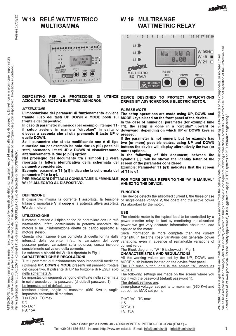
W 17 LIMITATORE DI CARICO
Multigamma, a inserzione diretta fino a 40A
(22kW-400V)
(Non è prevista l'applicazione con INVERTER o SOFT
START)
Il dispositivo può considerarsi l'evoluzione dell'E404-1,
conforme alla NORMA: EN 15011 : 2011.
“BASSA TENSIONE" - LVD CEI-EN 61010-1
COMPATIBILITA' ELETTRO MAGNETICA CEI-EN 61326-1
DEFINIZIONE
Controlla la potenza attiva assorbita da un motore a 2
polarità (o 2 velocità) oppure da 2 motori a una polarità,
oppure un motore ad 1 polarità.
UTILIZZAZIONE
Applicato per il controllo e la limitazione del carico sollevato,
al posto delle CELLE di CARICO.
CARATTERISTICHE E REGOLAZIONI
Il frontale è diviso in due zone, a sinistra c'è la zona dedicata
alla marcia LENTA, a destra c'è la zona dedicata alla marcia
VELOCE.
I settaggi e le regolazioni presenti nella sezione L - Lenta
sono: a, b, TCL, INL e DSL.
I settaggi e le regolazioni presenti nella sezione V - Veloce
sono: a, b, TCV, INV e DSV.
Il tempo di ritardo TR non ha regolazione esterna.
"a" Soglia di intervento impostabile a cacciavite, divisa in
10 parti. Alla tacca "10" corrisponde il fondo scala (in
potenza attiva) della GAMMA scelta con l'attivazione
del DSL (o DSV). Questa soglia è disabilitata durante il
tempo impostato con TCL (o TCV). Questi timer si
attivano quando la (I) supera la Im della gamma scelta.
I valori impostabili con “aL” ed “aV” possono essere
controllati con un tester in Vdc, nei due morsetti point
posti sul fronte del dispositivo (10Vdc max).
I due punti della morsettiera sul frontale (aL, aV) sono
uscite analogiche. L’operatore deve fare i collegamenti a
dispositivo non alimentato e avendo controllato di non
essere carico di elettricità statica. (E’ stata apposta
l’etichetta nera Sensitive to “ESD” - ESD=Electrostatic
Discharge).
"b" Soglia di intervento che può essere uguale ad "a" o
superiore ad "a" fino al 5%. Questa soglia non è
disabilitata da alcun timer. Si veda Fig. 2, riconosce la
presenza di un picco di carico (troppo elevato) per cui
viene fermato istantaneamente.
TCL / TCV
Tempo di "cecità" regolabile a cacciavite (0,1÷1s) che
disabilita la soglia di intervento "a" alla partenza del
motore (quando la I supera la Im della gamma scelta).
TR Tempo di ritardo (1s. fisso, non accessibile) che ritarda
la partenza della VELOCE per permettere alla soglia "a"
W 17 LOAD LIMITER
Multirange, direct insertion up to 40A (22kW-
400V)
(No Application with INVERTER or SOFT START)
The device is the evolution of E404-1 developed,
complying with STANDARD : EN 15011 : 2011.
LVD - "LOW VOLTAGE" CEI-EN 61010-1
ELECTROMAGNETIC COMPATIBILITY CEI-EN 61326-1
FUNCTION
It monitors the active power absorbed by a 2 pole motor
(or 2 speeds motor), or two motors with one speed, or one
motor with one speed.
USE
Applied for monitoring and limiting the hoisted load, in
place of LOAD CELLS.
CHARACTERISTICS AND REGULATIONS
The front panel is divided in two sections: the section on
the left is for the SLOW operation, section on the right is
for the FAST operation.
The settings and adjustments of section L (SLOW) are: a,
b, TCL, INL e DSL.
The settings and adjustments of section V (FAST) are: a,
b, TCV, INV e DSV.
The Delay Time TR has no external regulation
"a" Triggering set point, set by screwdriver, divided in 10
parts. The tick mark "10" corresponds to the full scale
(expressed in active power) of the range which has
been activated through DSL or DSV. This set point is
disabled during the time set by TCL or TCV. These
timers are active when (I) overcomes Im of the
selected range.
The values which can be set through “aL” ed “aV” can
be checked by a Vdc tester on the two terminals on
the front of the device (10Vdc max).
The two terminals on the front (aL, aV) are analogic
outputs. The operator must make the wirings when the
device is “not supplied” and must be sure not to be
charged with static electricity (See the black label:
Sensitive to “ESD”).
"b" Triggering set point which may be of the same value
or up to 5% higher than “a”. No timer disables this set
point.
Make ref to Fig.2, it detects a too high peak of load
and it stops hoisting immediately.
TCL / TCV
Delay time, adjustable by screw driver (0,1÷1s); it
disables the triggering set point “a” at the motor start
up. (when I overcomes Im of the selected range).
TR Delay time (1s. fixed, not adjustable) delaying
start up of the FAST operation in view of allowing that the
ATTENZIONE: Verranno riparati in garanzia, fra
nco ns sede, i dispositivi guasti per difetti sui materiali, entro
24
mesi dalla data di consegna. Emirel non è in alcun caso responsabile
per danni, diretti o indiretti, a persone o cose, che derivano da: mancato funzionamento, manomissioni, uso errato od improprio dei propri dispositivi di Protezione e Controllo.
Per le applicazioni "in SICUREZZA" si consiglia l'uso di sistemi di SICUREZZA o l'uso di tecniche di "RIDONDANZA".
WARNING: Repairs in guarantee are made free our factory, within
2
4
months from the delivery date, for the devices not working due to defects of the components. In no case Emirel
can be held responsible for damages, direct or indirect, occurred to things or people in consequence of wrong connections, accidents, not correct use or not operation of the Protection and
Control devices of its own production. For the "safety applications", it is suggested to apply SAFETY systems or REDUNDANCY engineering.".

Viale Caduti per la Libertà, 4b - 40050 MONTE S. PIETRO - BOLOGNA (ITALY) –
2Tel. 051/6761552 - Internet: http://www.emirelsrl.it - E-mail: [email protected] – i[email protected]
di intervenire nella fase LENTA.
Al termine della procedura di collaudo, si consiglia di
togliere la morsettiera femmina posta sul pannello.
NOTA 1
La filosofia del sistema impone che anche con il comando
VELOCE, il sistema parta in LENTA; dopo TCL + TR si
ecciterà il relè RB, che abiliterà la VELOCE e la corrente
attiverà TCV, che disabiliterà la soglia "a" per la VELOCE.
(V. Fig. 3, Fig. 4 e Nota 2).
NOTA 2
L'utilizzatore deve collegare la pulsantiera in modo che
anche in sollevamento "veloce", il sistema parta sempre in
"lenta" e passi poi in "veloce" quando commuterà il relè B
(cioè dopo TCL+TR = 2sec max).
In Fig.4 è riportato un esempio: il pulsante FAST ha un
contatto in più che fa partire la LENTA; quando si chiuderà
b1 (contatto di B) partirà la VELOCE.
INL / INV
Impostazione del valore della CORRENTE NOMINALE del
motore con regolazione a cacciavite, divisa in 10 tacche.
Nella Tab.1 sono riportati per alcune taglie di motori:
PN: Potenza Nominale in kW
IN: Corrente Nominale in A (per V=400Vac)
NW17: numero di giri che il conduttore della corrente deve
fare nel W17 (v. Fig. 5).
IN [TACCHE]: la tacca da impostare sulla regolazione IN… (il
valore di IN può essere controllato con un tester in
VDC sulle uscite 8-30 (LENTA), 9-30 (VELOCE) per
le varie gamme, V. Tab. 2).
GAMMA: valore del fondo scala da scegliere con il DSL
(DSV).
TA (ESTERNO): il valore del TA esterno da usare quando
IN è maggiore di 40A.
NTA: il numero di giri che il conduttore di corrente deve fare
entro il foro del TA esterno.
NOTA: Il TA esterno dovrebbe avere una
PRESTAZIONE ³5VA per rispettare il
FATTORE DI POTENZA.
NOTA 3
Per valori di tensione motore diversa da 400Vac, i dati di In
ed In tacche riportati in TAB.1 vanno ricalcolati come da
esempio: V=230V P= 5,5kW => IN=20A => GAMMA
DS(L)/DS(V)=3 INTACCHE (In/2)=10.
V=415V si può tenere come riferimento i valori di 400V in
TAB.1.
V=440, 450V, 460V... ecc si deve usare M08 per ridurre la
tensione.
V=460V P=5,5kW IN=10A => GAMMA DS(L)/DS(V)=2 => IN
TACCHE (Inx1)=10.
set point “a” triggers during the SLOW operation.
At the end of the test procedure, it is recommended to
remove the female terminal located on the panel.
REMARK 1
The system is based on the principle that also under the
FAST command, the application starts under SLOW
operation; hence after TCL + TR the RB relay changes
over enabling the FAST operation, the current will activate
TCV, this will disable the set point “a” for the FAST
operation (ref. Fig.3, Fig.4 and Remark 2).
REMARK 2
The operator must connect the push button panel in such a
way that even when the application is in “fast” operation
the system starts always in “slow” operation, changing to
“fast” operation when the RB relay changes over (after
TCL+TR= 2 sec max).
Fig.4 shows an example: the push button FAST is
provided with an additional contact which makes the
SLOW operation starts; when “b1” (Contact of B) will be
closed, the FAST operation will start.
INL / INV
Setting of the motors NOMINAL CURRENT value, by
screwdriver; adjustment, divided in 10 tick marks. Tab. 1
shows for some models of motors the following
information:
PN: Nominal Power in kW
IN: Nominal Current in A (for V=400Vac)
NW17: number of windings to be made with the current wire
inside W17 (ref. Fig. 5).
IN [TACCHE]: the tick mark to be selected on the regulation
IN... (the value of IN can be controlled with a VDC
tester on the outputs 8-30 (SLOW), 9-30 (FAST) for
the different ranges, see tab.2)
RANGE: full range value to be selected with DSL (DSV).
CT (EXTERNAL): value of the external CT to be applied
when IN is higher than 40A.
NTA: number of windings to be made with the current wire
inside the hole of the external CT.
REMARK: The external CT must have the BURDEN
³
5VA
to
not modify
the POWER FACTOR.
REMARK 3
For voltage values outside 400Vac, the data of INed IN
TACCHE showed in TAB.1 have to be reconsidered such as:
V=230V P= 5,5kW => IN=20A => RANGE DS(L)/DS(V)=3
INTACCHE (In/2)=10.
V=415V the reference values are the same of 400V in
TAB.1.
V=440, 450V, 460V...etc M08 must be applied to reduce
the voltage.
V=460V P=5,5kW IN=10A => RANGE DS(L)/DS(V)=2 =>
I
N
TACCHE
(Inx1)=10.

Viale Caduti per la Libertà, 4b - 40050 MONTE S. PIETRO - BOLOGNA (ITALY) –
Tel. 051/6761552 - Internet: http://www.emirelsrl.it - E-mail: info@emirelsrl.it – [email protected] 3
INx2
GAMME /
RANGES
POT. MAX
TEOR / THEOR
MAX POWER
SENS.USC.
ANALOGICA / SENS
ANALOG OUTPUT
5 A 3,5 kW 1V=0,35 kW
10 A 7 kW 1V=0,70 kW
20 A 14 kW 1V=1,40 kW
30 A 21 kW 1V=2,10 kW
40 A
28 kW
1V=2,80 kW
NOTA: Il fondo scala della veloce deve
essere già scelto, sul “DSV”, quando si
fa la taratura LENTA.
REMARK: The fast range must be
already set, on “DSV”, during SLOW
CALIBRATION.
TAB. 3
TAB. 1
TABELLA MOTORI /
MOTORS TABLE
NOTE :
1: N: Numero di passaggi del filo entro il foro
del W17 o del TA esterno.
2: si suppone che I0(Corrente con Gancio
vuoto) sia @1/3 IN.
3: IN=Corrente Nominale del Motore
REMARKS :
1: N: Number of windings through W 17 or
through on external CT.
2:
I0
(Current with no load) is supposed to be
@
1/3
IN
.
3:
IN
= Nominal Current of the Motor.
PN[kW]
IN(400V)
[A]
N
IN
TACCHE
TICK
MARKS
GAMMA
RANGE
TA
ESTERNI
EXTERNAL
CT
N TA
0,06
0,09
0,12
0,18
0,25
0,37
0,55
0,75
1,10
1,50
2,20
0,2
0,3
0,4
0,6
0,8
1,1
1,5
1,9
2,6
3,6
5
9
6
5
3
3
2
2
1
1
1
1
3,5
3,5
4,0
3,5
4,8
4,5
6
4
5
7,2
10
5 A / /
ESEMPI / EXAMPLES:
IN(Tacche) = IN(W17) x2
Verif.: I0(W17) > 0,5A
Es. IN=0,2A I0=IN/3 = 0,066
I0(W17)=0,066x9=0,6A>0,5A
IN(TACCHE)=0,2x9x2=1,8x2=3,6A
3
4
6,6
8,5
1
1
6,5
8,5
10 A / / Verif.; I0> 1A
5,5
7,5
11,3
15,2
1
1
5,5
7,5
20 A / / Verif.: I0> 2A
11
15
21,7
29,3
1
1
7
10 30 A / / Verif. che I0> 3A
18,5
22
36
41
1
1
9
10
40 A / / Verif.: I0> 4A
30 55 1 9
5 A
60/5 1
RR=60/5=12
I0(W17)=(55/3)/12=1,5>0,5A
IN(
TACCHE
)=4,6A®I
N
(
TACCHE
)@9
37
45
55
68
81
99
1
1
1
7
8
10
100/5
100/5
100/5
1
1
1
RR=100/5=20
I0(W 17)=(68/3)/20=1,13A>0,5A
IN(
TACCHE
)=68/20=3,4Ax2@7
75 134 1 9 150/5 1
RR=150/5=30
I0(W 17)=(134/3)/30=1,48A>0,5A
IN
(
TACCHE
)=134/30=4,5Ax2=9
90
110
161
196
1
1
8
10 200/5 1
RR=200/5=40
I0(W 17)=(161/3)/40=1,34A>0,5A
IN(TACCHE)=161/40=4Ax2=8
TAB. 2
V PIN 8
VPIN 9
(VOLT DC)
IN(L)
IN(V)
(TACCHE)
(TICK MARKS)
GAMMA
/
RANGE
DS (L) / DS (V)
1=ON 2=ON 3=ON 4=ON 5=ON
5 A 10 A 20 A 30 A 40 A
10 V
8 V
6 V
4 V
2 V
10
8
6
4
2
5 A
4 A
3 A
2 A
1 A
10 A
8 A
6 A
4 A
2 A
20 A
16 A
12 A
8 A
4 A
30 A
24 A
18 A
12 A
6 A
40 A
32 A
24 A
16 A
8 A
0,5 A
1 A
2 A
3 A
4 A
Im (A)
I
N
x
1
I
N
/3
I
N
/2
I
N
/4

Viale Caduti per la Libertà, 4b - 40050 MONTE S. PIETRO - BOLOGNA (ITALY) –
4Tel. 051/6761552 - Internet: http://www.emirelsrl.it - E-mail: [email protected] – i[email protected]
DSL / DSV
Dip switch a 5 cursori che servono per impostare la GAMMA
della corrente. Il dip switch si attiva posizionando il cursore
verso il basso (si deve attivare un solo cursore). In Tab. 2
sono riportate le corrispondenze fra i cursori e le gamme.
Per ogni gamma è riportata anche il valore di Im (il valore di
corrente al cui superamento si attiva TCL e TCV).
In tabella è riportata anche la corrispondenza fra il valore di
IN e l’impostazione di IN… e il valore che si leggerà ai pin 8-
9.
Esempio: con un motore con IN=12A si attiva il cursore 3
(20A fondo scala), si fissa IN sulla tacca 6 e sul pin 8 (o 9) si
deve trovare 6V (eventualmente si corregge l'impostazione
di IN…). Nella parte bassa della Tab. 2 sono indicate le
relazioni fra i valori del pin 8/9 con il valore di IN,
nell'esempio il valore in Volt del pin 8/9 è la metà del valore
di IN.
VISUALIZZAZIONI
ON: led VERDE: dispositivo alimentato.
: led VERDE: visualizza l'impulso di corrente ad ogni
partenza. Il led si accende per ogni partenza,
LENTA o VELOCE, poi si deve spegnere. Se il led
rimane acceso (relé A=OFF) verificare che il rotore
non sia bloccato o l'impostazione di IN non sia
sbagliata.
I>>IN: led ROSSO: allarme se I resta maggiore di IN
(ROTORE BLOCCATO).
Dopo un secondo dalla partenza della LENTA o
della VELOCE, se il led è acceso, si accende I>>IN
(relé A= OFF). Verificare che il rotore non sia
bloccato o la gamma scelta sbagliata.
"a" led ROSSO: supero della soglia "a" LENTA.
"b" Lled ROSSO: supero della soglia "b" LENTA.
A led ROSSO: allarme: intervento del relè RA.
"a" led ROSSO: supero della soglia "a" VELOCE.
"b" Vled ROSSO: supero della soglia "b" VELOCE.
B led GIALLO: il relè RB va ON per l'eventuale
passaggio in VELOCE.
PARTENZE RIPETUTE
Il dispositivo è dotato di un controllo contro le partenze
troppo frequenti. Se vengono eseguite 9 partenze
consecutive di durata inferiore a 0,5 sec., il dispositivo va in
ALLARME. Se almeno una partenza dura più di 0,5 sec. il
conteggio si azzera. Se si esegue il cav. 18-19 il controllo è
escluso.
RIPRISTINO
Avviene alimentando con una tensione alternata 20÷230
VAC fra i pin 10-11 per almeno 0,5 sec. (si può usare una
tensione DC con il + su 11). E' bene che il ripristino sia
abbinato al comando di DISCESA per evitare il sollevamento
di carichi non permessi, sfruttando più volte il sollevamento
iniziale.
TARATURA
Il dispositivo tratta il motore della LENTA e quello della
VELOCE come due motori separati, ognuno caratterizzato
dalla propria IN (corrente nominale, di targa); il
procedimento di taratura è quindi uguale per i 2 motori.
Partendo dalla potenza del motore, con la Tab. 1, si ricava la
IN (oppure si conosce la IN del motore dai dati di targa).
In base al valore di IN, da Tab. 1 si ha già una scelta della
GAMMA, oppure si può usare la Tab. 2.
Esempio: MOTORE P=4kW IN=8,5A (400V) dalla Tab. 2 si
vede che il valore 8,5A è nella gamma 10A ma anche nella
20A e nella 30A, nella 40A. Si sceglie 10A (DS2=ON)
perché in questa gamma la sensibilità è maggiore (Vedere
Tab. 3).
Avendo scelta la gamma si conosce (Tab. 2) il valore di Im
(1A in questo caso) che rappresenta il minimo della gamma.
Il superamento di questo valore attiva i Timer TCL e TCV,
quindi si dovrà verificare che la corrente I0a "GANCIO
SCARICO" sia maggiore di Im
(I
0
> Im !!!)
.
DSL / DSV
Dip switch with 5 sliders used to select the current
RANGE. The dip switch is activated by pushing the slider
downwards (one slider only can be activated). Tab. 2
shows the matching values between sliders and ranges.
For each range the value of Im is present. When I
overcomes Im, TCL and TCV are activated. Tab. 2 shows
also the matching value between IN and the set value with
IN and the value read out at the pins 8-9. Example: with a
motor with IN=12A, the slide 3 is ON (20A full range); IN...
is set on the tick mark 6 and on the pin 8 or 9 the value of
6V is read out. (Correction to IN... setting may be made).
In the low section of the Tab. 2 are showed the ratio
between the values of pin 8-9 with the value of IN. In the
example, the value in Volt of pin 8-9 is half IN value.
VISUALIZATIONS
ON: GREEN led: supply on
: GREEN led: it monitors the current pulse at each
start up. The led lights on at each SLOW or FAST
start up, and immediately after the led must turn
off. If the led remains lighted (A relay=OFF) check
out if rotor is stalled or IN (nominal current) setting
is wrong.
I>>IN: RED led: alarm when I is higher than IN
(STALLED ROTOR ). One second after SLOW or
FAST operation starts up, if the led lights on,
I>>IN lights on (A relay = OFF). Check out if rotor
is stalled or RANGE setting is wrong.
"a" RED led : overcome of set point "a" SLOW.
"b" LRED led : overcome of set point "b" SLOW.
A RED led : alarm: triggering of RA relay.
"a" RED led : overcome of set point "a" FAST.
"b" VRED led : overcome of set point "b" FAST.
B YELLOW led: RB relay goes ON for the starting of
the FAST operation.
TOO MANY STARTS UP
The device is provided with too many starts up control. In
case of 9 consecutive starts up (lasting less than 0,5 sec),
the device goes in alarm. If at least one start up last more
than 0,5 sec, the counter resets.
This function is excluded if the link 18-19 is made.
RESET
The reset takes place by connecting alternating cur
rent
20÷230 VAC between the pins 10-11 for at least 0,5 sec.
(DC voltage can be applied with + on 11). It is necessary
that the reset function is connected together with the
LOWERING command, in order to prevent hoisting of
loads not admitted, using many times the TCL of the
START.
SETTING
The device treats the SLOW and FAST motor as two
different units, each one featured by its IN (nominal plate
current); the process is the same for the two motors.
First step: motor power: Tab. 1 is used to identify IN (in
alternative the motor IN is read out from the motor plate).
The RANGE is evidenced in Tab 1, basing on IN, or Tab. 2
is applicable.
Example: MOTOR P=4kW IN=8,5A (400V) Tab. 2 shows
that the value 8,5A is included in the range 10A as well as
in the range 20A, 30A, and 40A. The range 10A (DS2=ON)
is better because the sensitivity is better (See Tab. 3).
In correspondence of the range (see Tab. 2) the value of
Im (1A in this case) is pointed out (Im = minimum range
value). When Im overcomes, the timers TCL and TCV
become active; it is indispensable to check that I0is higher
than Im with UNLOADED HOOK (I0> Im !!!).
Select the INL/INV value on the device front panel: Tab. 2
shows that in the
RA
NGE 10A, 8A corresponds to the tick

Viale Caduti per la Libertà, 4b - 40050 MONTE S. PIETRO - BOLOGNA (ITALY) –
Tel. 051/6761552 - Internet: http://www.emirelsrl.it - E-mail: info@emirelsrl.it – [email protected] 5
Ora si deve impostare il valore di INL/INV sul frontale,
mediante la Tab. 2 che indica che nella GAMMA 10A ad 8A
corrisponde la tacca 8, quindi ad 8,5A corrisponderà una
posizione fra 8 e 9 e si può regolare più accuratamente
l'impostazione di INL/INV con un tester sull'uscita 8/9,
regolando INL/INV per 8,5V.
Il valore da impostare con la regolazione INL/INV è legato al
valore di IN espresso in Ampere, a seconda del fondo scala
scelto con il cursore:
Gamma 5A: la tensione è il doppio del valore di IN
(Es.: IN=4,5A V8/9=9Vdc)
Gamma 10A: la tensione è uguale al valore di IN
(Es.: IN=8,5A V8/9=8,5Vdc)
Gamma 20A: la tensione è metà del valore di IN
(Es.: IN=16A V8/9=8Vdc)
Gamma 30A: la tensione è un terzo del valore di IN
(Es.: IN=24A V8/9=8Vdc)
Gamma 40A: la tensione è un quarto del valore di IN
(Es.: IN=32A V8/9=8Vdc)
Regolare per la sez. LENTA "a", "b", TCL al massimo.
Porre un tester sull'uscita analogica 31-30 (+su 31), il valore
che si leggerà sollevando il peso corrisponderà al valore di
"a" che lo farà scattare. (Es.: se sollevando un peso l'uscita
analogica va a 6V, regolando "a" sulla tacca 6 si avrà
l'intervento del relè RA).
Sollevando il PESO CAMPIONE (esempio 110% della
PORTATA NOMINALE della gru) regolare "a" per avere
l'intervento del W 17.
Eseguendo varie partenze si può diminuire "b" per verificare
l'eventuale esistenza di un primo picco nella forza di
sollevamento (fig. 2) e diminuire, se necessario, il TCL.
La stessa procedura va eseguita per la VELOCE, con lo
stesso PESO CAMPIONE.
Si sconsiglia di tenere i TC troppo corti, meglio tenere dei
margini che compensino l'invecchiamento.
NOTA 4
I morsetti del W 17 devono essere "svitati" a fondo prima del
cablaggio per evitare l'inserimento del filo nella "luce"
posteriore del morsetto (creerebbe dei contatti incerti).
NOTA 5
A GANCIO SCARICO la corrente può essere > Im ma la
potenza può essere tanto bassa da non essere impostabile
per le soglie (a causa del basso cos#) del motore "scarico".
SICUREZZA INTRINSECA
Il relè RA è normalmente ON e diseccita in caso di
intervento.
COLLEGAMENTI
Le fig. 6,7,8,9 riportano alcuni esempi che forniscono solo
suggerimenti per l'applicazione del W 17.
(Collegamento a un quadro elettrico con differenziale e
sezionatore). La lunghezza di ogni collegamento deve
essere < 30m.
Il W 17 deve essere alimentato ai pin 20-22 e collegato alla
tensione trifase con i pin 24-26-28 anche quando il motore è
fermo. MASSIMA sezione dei conduttori a treccia 2,5mm2,
filo pieno 4mm2.
NOTA 6
La fase di cui si misura la corrente (L2 negli schemi) (fase
amperometrica) deve essere collegata al pin 28 e non deve
essere usata per realizzare l'inversione del senso di
rotazione del motore. Le altre 2 fasi vanno collegate ai pin
24 e 26, senza alcuna preferenza.
Nota generale: Negli schemi di collegamento non sono
riportati i fusibili sulle alimentazioni e sugli ingressi
voltmetrici. I collegamenti elettrici devono essere eseguiti a
dispositivo e quadro elettrico spenti.
INGRESSI
I conduttori che portano la corrente della LENTA e della
VELOCE devono passare entro gli appositi fori del W 17,
contrassegnati dalla lettera S/L (LENTA), F/V (VELOCE).
mark 8, and consequently the value 8,5A will correspond
to a position between 8 and 9; IN setting can be more
accurate by connecting a tester on the output 8-9,
adjusting INL/INV on the value 8,5V.
The voltage value to be set by INL/INV has a ratio
connection with the value IN expressed in Ampere; the
ratio changes according to the full scale selected with the
slide:
Range 5A: voltage is double of the IN value
(Ex.: IN=4,5A V8/9=9Vdc)
Range 10A: Voltage and IN have the same value
(Ex.: IN=8,5A V8/9=8,5Vdc)
Range 20A: Voltage is half the IN value
(Ex.: IN=16A V8/9=8Vdc)
Range 30A: Voltage is one third of IN value
(Ex.: IN=24A V8/9=8Vdc)
Range 40A: voltage is one forth of IN value
(Ex.: IN=32A V8/9=8Vdc)
In the section SLOW, adjust to the max "a", "b", TCL.
Apply a tester on the analog output 31-30 (+ on 31); the
read out value, while hoisting the load, is correspondent to
the “a” value which makes the device change over. (Ex.: if
hoisting a load the analog output goes to 6V, the RA relay
changes over if “a” has been set on the tick mark 6).
Hoist the REFERENCE LOAD (Example 110% of the
crane nominal load) and adjust “a” in order to get W 17
triggering.
After several starts up, it is possible to decrease “b” in view
of finding out the presence of the first peak in the hoisting
force (fig. 2) and decrease, if necessary, the TCL.
The same procedure is to be effected in the FAST section,
with the same SAMPLE WEIGHT.
It is suggested to not to set TC times on too short values,
but to leave a margin for including ageing.
REMARK 4
Before effecting the electric wiring it is recommended to
unscrew the terminals completely, in order to avoid that the
wire is inserted in the back hole of the terminal (where it
could generate insecure contacts).
REMARK 5
When the HOOK is without LOAD, the current can be > Im,
but the power might be so low that is not suitable for
setting the set points for the motor without load (due to low
cos#).
POSITIVE SAFETY
The RA relay is normally ON and it goes OFF in case of
alarm.
ELECTRIC WIRINGS
Fig. 6,7,8,9 show some examples as guide-line and
suggestions only for application of W 17.
(Wiring to an electrical board with a differential relay and a
sectionalizing switch).
The length of every wiring must be less than 30m.
W 17 is supplied at the pins 20-22 and connection to the
three phase voltage by the pin 24-26-28, also when the
motor is not in operation.
Maximum section of the braid conductors 2,5mm2, full wire
4mm2.
REMARK 6
The phase measuring the current (L2 in the scheme)
(current phase) must be connected to pin 28 and it cannot
be used to perform the reverse the operation direction of
the motor. The other two phases must be connected to the
pins 24 and 26, without any preference.
General remark: The wiring diagrams do not show the
fuses installed on the supply and on the voltmetric inputs.
The electric wirings must be realized with device and
electrical panel in off condition.
INPUTS
The wires carrying the SLOW and FAST current, must
enter through the suitable holes of W 17, marked by S/L

Viale Caduti per la Libertà, 4b - 40050 MONTE S. PIETRO - BOLOGNA (ITALY) –
6Tel. 051/6761552 - Internet: http://www.emirelsrl.it - E-mail: [email protected] – i[email protected]
Il senso in cui passano nel foro non ha importanza.
Le 3 tensioni vanno collegate ai pin voltmetrici 28-26-24
(Ring=800kohm).
La tensione massima trifase è 415 Vac. Per tensioni
maggiori si deve utilizzare M 08: resistenze di caduta (V.
accessori) (V. Fig. 10 e TAB. A).
Per valori di tensione motore diversi da 400V, i valori di
riferimento di In ed In tacche descritte in TAB. 1 vanno
ricalcolati (vedi nota 3).
USCITA ANALOGICA
Ai pin 31-30 (+ su 31) è disponibile una tensione 0÷10V
(1mA max) proporzionale alla potenza attiva assorbita,
quindi proporzionale al peso sollevato. I volt dell'uscita
analogica hanno un "peso" diverso a seconda della gamma
della corrente V. Tab. 3. Può essere visualizzata durante la
taratura e durante l'esercizio della gru per fornire
all'operatore un'informazione sull'entità del peso sollevato.
Può essere utilizzata con un relé di tensione CC (VD 04
oppure E 411) per preallarmi, oppure può essere
visualizzata con il Voltmetro in DC DVD 08.
USCITE: (3A - 230 Vac carico resistivo)
Relè RA: pin 16-17 NA (normalmente ON) tutte le condizioni
di allarme lo mandano OFF, serve per interrompere il
sollevamento.
Relè RB: pin 13-14 NA (si chiude per passare in VELOCE)
permette il passaggio in VELOCE se non c'è stata una
condizione di "ALLARME" durante TR, in LENTA (Fig.3).
NOTA 7
Si consiglia vivamente l'uso degli SNUBBER "RC" sulle
bobine dei teleruttori (impiegare quelli previsti dal costruttore
dei teleruttori).
NOTA 8
Non lasciare fili con estremità non collegate, ai pin 8, 9, 30,
31.
ALIMENTAZIONE
2VA 50-60 Hz ±10%
PIN 20-22: 230 VAC o 115 VAC o 48 VAC o 24 VAC
ISOLAMENTO: separazione galvanica tramite il trasfor-
matore di alimentazione.
DIMENSIONI: 100x75x110 mm per DIN
Accessori (a richiesta):
E 405 A: protezione trasparente piombabile.
M 08: resistenze di caduta per V > 415V.
TEMPERATURA DI FUNZIONAMENTO: -10°C÷+60°C
PESO: 0,500 Kg - COLORE: grigio.
AVVERTENZE
1) Sul dispositivo sono presenti tensioni di 230V-400V che
possono rappresentare un grave pericolo; solo personale
addestrato ad operare in presenza di queste tensioni
dovrebbe accedere al dispositivo.
2) Il personale addetto ad operare su questo dispositivo
deve leggere attentamente tutte le istruzioni e le note che
riguardano il dispositivo prima di operare su di esso.
3) Il dispositivo non deve essere manomesso o modificato.
MISURE DI SICUREZZA
Il dispositivo DEVE essere installato esclusivamente
all'interno di un quadro elettrico chiuso mediante chiave o
dispositivo analogo. L'accesso al suddetto quadro e di
conseguenza al dispositivo DEVE essere effettuato
esclusivamente a quadro disalimentato e SOLO dal
personale di manutenzione o di installazione
opportunatamente formato ed addestrato alla operazione
prevista.
Per la pulizia usare un panno imbevuto di detergenti privi di:
Alcool denaturato, Benzene, Alcool isopropilico.
FUNZIONAMENTO
Al termine della procedura di taratura, il W 17 deve
effettuare
le seguenti
funzioni.
(SLOW), F/V (FAST). No fixed direction is required in
making the wires pass through the holes.
The 3 phases are connected to the pins 28-26-24 (Input
R=800kohm).
The maximum three phase voltage is 415 Vac. For higher
voltages the Drop Resistance M 08: must be applied (See
accessories) (Ref. Fig. 10 and TAB. A).
For motor voltage values outside 400V, the reference
values of In and In tick marks showed in TAB 1 have to be
reconsidered, (see remark 3).
ANALOG OUTPUT
On the pins 31-30 (+ on 31) it is available a voltage 0÷10V
(1mA max) proportional to the active absorbed power, and
consequently proportional to the hoisted weight. The volts
of the analog output correspond to a different value of kW,
according to the range of the current (see Tab. 3).
The analog output can be displayed during the setting
operation or the crane working in order to give to the
operator information regarding the size of the hoisted
weight.
Il can be used with a DC Voltage relay (VD 04 or E 411)
for a pre-alarm or with an DVD 08 for a permanent display.
OUTPUTS: (3A - 230 Vac resistive load)
RA relay: pin 16-17 NO (normally ON) all the alarm
conditions make it change in OFF condition; it is used to
stop hoisting.
RB relay: pin 13-14 NO (it closes for changing to FAST).
If in SLOW operation (during TR), no ALARM condition
has taken place, it allows change over FAST speed.
(Fig.3).
REMARK 7
It is warmly suggested the application of SNUBBER "RC"
on the contactor coils (it is preferable to use those
recommended by the contactor manufacturer).
REMARK 8
Do not leave floating wires connected to pins 8, 9, 30, 31.
SUPPLY
2VA 50-60 Hz ±10%
PIN 20-22: 230 VAC or 115 VAC or 48 VAC or 24 VAC
INSULATION: galvanic separation it is given by the supply
transformer.
SIZE: 100x75x110 mm per DIN
Accessories (on request):
E 405 A: Transparent protection, fitted for lead closure,
M 08: Drop resistances for V > 415V.
WORKING TEMPERATURE: -10°C÷+60°C
WEIGHT: 0,500 Kg - COLOUR: grey.
WARNINGS
1) The serious danger which may happen in presence of
voltages 230V-400V on the device, requires that the
device is accessible only to skill staff specialized in
operating with such voltages.
2) The staff assigned to operate with this device is
requested to carefully read all the instructions, remarks
and warnings before starting to work with it.
3) The device cannot be tampered or modified.
SECURITY MEASURES
The device MUST be installed only inside a electrical panel
closed by a key or similar device. Access to this electrical
panel and consequently at the device MUST be done
exclusively with panel switched off and ONLY by
maintenance or installation personnel suitably formed and
trained for the planned operation.
For cleaning use a cloth soaked with detergents without:
Denatured Alcohol, Benzene, Isopropyl alcohol.
MODE OF OPERATION
At the end of the setting procedure the device W 17 shall
have to perform the following functions.

Viale Caduti per la Libertà, 4b - 40050 MONTE S. PIETRO - BOLOGNA (ITALY) –
Tel. 051/6761552 - Internet: http://www.emirelsrl.it - E-mail: info@emirelsrl.it – [email protected] 7
§MOTORE FUNZIONANANTE A VELOCITA' LENTA
- Si accende per qualche attimo il led verde
- Dopo un tempo massimo di 2 sec si deve accendere il led
giallo B.
- Se alla partenza il rotore è bloccato, si accendono i 2 led
rossi: “I>>IN” ed “A”, ed il relé A cade.
- Se alla partenza, riconosce la presenza di un picco di
carico (troppo elevato) maggiore del valore impostato dalla
soglia "b", il relé A va subito in allarme e si accendono i led
rossi "a" e "b".
- Se durante il funzionamento in LENTA si ha un supero di
potenza, il relé A va in allarme e si accendono i led "a" della
lenta ed il led A.
§MOTORE FUNZIONANTE A VELOCITA' VELOCE
La pulsantiera deve essere cablata in modo tale che anche
quando si da il comando veloce, il sistema deve partire in
lenta, poi passare in veloce, comandato dal relè RB.
§AVVIARE MARCIA VELOCE
Il motore parte a velocità lenta, su W 17 si accende per un
attimo il led verde, poi dopo 2 sec max dalla partenza, si
accende il led giallo B, ed assieme il relé RB va ON,
attivando la velocità veloce, e si vede che il led verde si
riaccende per qualche attimo.
- Se il rotore è bloccato alla partenza, si accendono i led
rossi “I>>IN” ed “A”, ed il relé A cade,
- Se alla partenza, riconosce la presenza di un picco di
carico (troppo elevato) maggiore del valore impostato dalla
soglia "b" il motore si fermerà e si accendono i led "b" ed A
ed i relé cadono.
- Se durante il funzionamento veloce, si presenta un supero
di potenza, i led "a" della veloce ed “A” si accendono ed i 2
relé cadono.
A bassa temperatura, la diminuzione della fluidità
dell’olio (o del grasso) del riduttore, aumenta la potenza
assorbita (anche del 10%). Riscontrabile misurando Ua.
Se si eseguono varie salite, con carico, si nota che il
valore della Ua diminuisce anzichè eventualmente
aumentare. Può essere necessario l’uso di SCALDIGLIE.
§MOTOR IN SLOW SPEED MODE
- The green led lights on for a short while.
- After a time of 2 sec max the yellow led B lights on.
- It at the start up the rotor is stuck, the 2 red leds: “I>>IN”
and “A”, lights on and the A relay drops.
- If at the start up, it detects a too high peak of load, higher
than the value set by the "b" set point, the A relay goes in
alarm and the red leds "a" and "b" light on.
- If during the SLOW mode the power is overcome, the A
relay goes in alarm and the leds "a" of the SLOW and the
“A” led light on.
§MOTOR IN FAST SPEED MODE
The push-button panel must be connected in such a way
that even when the application is in “fast” mode, the
system starts always in “slow” mode, changing to “fast
mode when the RB relay changes over.
§FAST MODE START
The motor starts in slow mode, and for a short while the
green led lights on W 17; 2 secs max after start up, the
yellow led B lights on, and the RB relay goes ON, making
the fast speed start and showing the green led lighting
again for a short while.
- If the rotor is stuck at the start up, the red leds “I>>IN”
and “A” light and the A relay drops.
- If at the start up, it detects a too high peak of load, higher
than the value set by the "b" set point, the motors stops,
the red leds "b" and "A" light on, and the relays drop.
- If during the FAST mode the power is overcome, the leds
"a" of the fast and “A” light on and the 2 relays drop.
At low temperature, the fluidity of oil (or grease) in the
reduction gear increases the electrical input (also
10%). Is possible sea this measuring Ua (Analog
Output). If you make some lifting, with load, you will
sea that Ua decreases. Maybe an heater is required.
Fig.5 bis
GAMME / RANGES TAB. A
Mod.
Tensione $
Voltage!
Primario
Primary
Secondario
Secondary
M 08-1
M 08-2
M 08-3
M 08-4
M 08-5
M 08-6
M 08-7
M 08-8
M 08-9
M 08
-
10
450V
500V
600V
660V
460V
480V
690V
440V
575V
525V
400V
400V
400V
400V
400V
400V
400V
400V
400V
400V

Viale Caduti per la Libertà, 4b - 40050 MONTE S. PIETRO - BOLOGNA (ITALY) –
8Tel. 051/6761552 - Internet: http://www.emirelsrl.it - E-mail: [email protected] – i[email protected]

Viale Caduti per la Libertà, 4b - 40050 MONTE S. PIETRO - BOLOGNA (ITALY) –
Tel. 051/6761552 - Internet: http://www.emirelsrl.it - E-mail: info@emirelsrl.it – [email protected] 9
RIASSUNTO DELLA PROCEDURA DI TARATURA:
SUMMARY OF THE SETTING PROCESS:
POTENZA MOTORE (PN) (LENTA) / MOTOR POWER (PN) (SLOW)
CORRENTE NOMINALE (IN) (V=400V) (LENTA)
NOMINAL CURRENT (IN) (V=400V) (SLOW)
GAMMA (LENTA) (Dip Switch) (Verificare I0(Gancio vuoto)>Im)
RANGE (SLOW) (Dip Switch) (Check I0(Hook without load)>Im)
Impostare INL (Tab. 2) (Verifica su PIN 8) / Set INL (Tab. 2) (Check on PIN 8)
Impostare i parametri (a, b, TCL) della LENTA al massimo
Set the values (a, b, TCL) of SLOW to the maximum
Sollevare il PESO CAMPIONE / Hoist the SAMPLE WEIGHT
Abbassare la regolazione di “a” fino all’intervento del relè RA
Turn down “a” regulation until RA relay triggers
Verificare che la tensione dell’uscita analogica (pin 31-30)
corrisponde al valore trovato con “a”
Check analog output value (pin 31-30) matching with the value found with “a”
Eseguire varie partenze, diminuendo “b” per verificare la presenza
della elongazione iniziale (Fig. 2) / Make several starts up,
decreasing “b” to detect a too high initial peak of load (Fig. 2)
Diminuire eventualmente TCL /Decrease TCL if required
POTENZA MOTORE (PN) (VELOCE) / MOTOR POWER (PN) (FAST)
CORR. NOMINALE IN(V=400V) (VELOCE)
NOMINAL CURRENT IN(V=400V) (FAST)
GAMMA VELOCE (DIP SWITCH) (Verificare I0>Im)
RANGE FAST (DIP SWITCH) (Check I0>Im)
Impostare INV (Tab. 2) (Verifica su pin 9) / Set INV (Tab. 2) (Check on pin 9)
Impostare i parametri (a, b, TCV) della veloce al massimo
Set the values (a, b, TCV) of FAST to the maximum
Sollevare il PESO CAMPIONE / Hoist the SAMPLE WEIGHT
Abbassare la regolazione di “a” fino all’intervento del relè RA
Turn down “a” regulation until RA relay triggers
Verificare che la tensione dell’uscita analogica (pin 31-30) corrisponda al valore trovato con “a”.
(Questa tensione può essere utilizzata per visualizzare, ad esempio in %, il carico sollevato)
Check analog output (pin 31-30) matching with the value found with “a”.
(This value can be used to display, for example, in % the hoisted load)
Eseguire varie partenze diminuendo “b” per verificare la presenza dell’elongazione iniziale
Make several starts up, decreasing “b” to detect a too high initial peak of load (Fig. 2)
Diminuire eventuale TCV. / Decrease TCV if required.
Table of contents
Other Emirel Relay manuals
Popular Relay manuals by other brands

GE
GE b30 Communications guide

CARLO GAVAZZI
CARLO GAVAZZI DPC01 manual
Honeywell
Honeywell NOTIFIER FRM-1 Installation and maintenance instructions

Leviton
Leviton EZ-MAX H Series quick start guide
Tiesse
Tiesse SAFE M: operating instructions
Pfeiffer Vacuum
Pfeiffer Vacuum HiPace PM 071 282-X operating instructions

Pilz
Pilz PNOZ X Series operating instructions

Pilz
Pilz PNOZSIGMA Series operating instructions

Munters
Munters Green Expansion installation manual
motogadget
motogadget mo.relay+ instruction manual

Siemens
Siemens SIRIUS 3RR24 operating instructions
ABB
ABB CT-S Series Operating and installation instructions
