Emirel V3-12-A User manual

Viale Caduti per la Libertà, 4b - 40050 MONTE S. PIETRO - BOLOGNA (ITALY) –
Tel. 051/6761552 - Fax 051/6760492 - Internet: http://www.emirel.it - E-mail: info@emirelsrl.it – info1@emirelsrl.it 1
Release 28/01/20
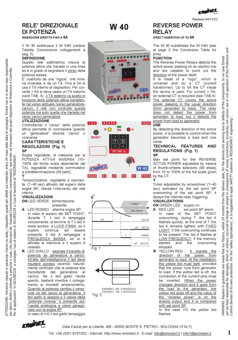
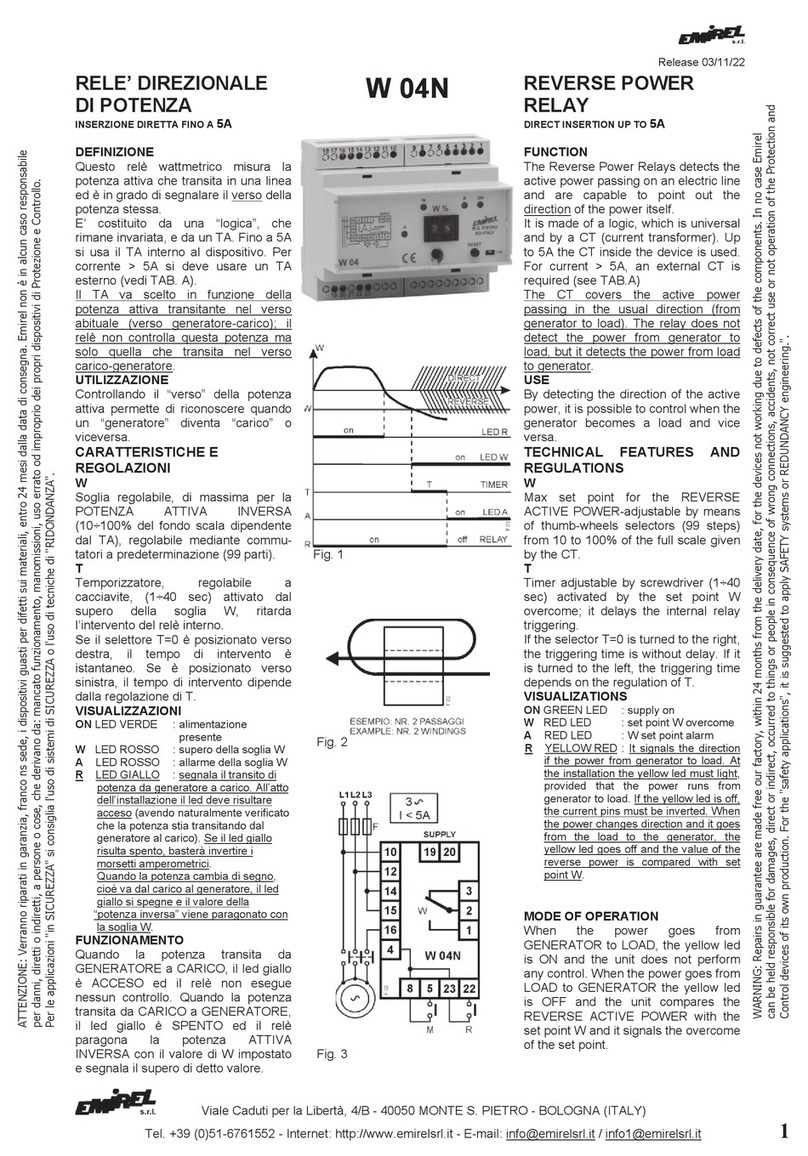
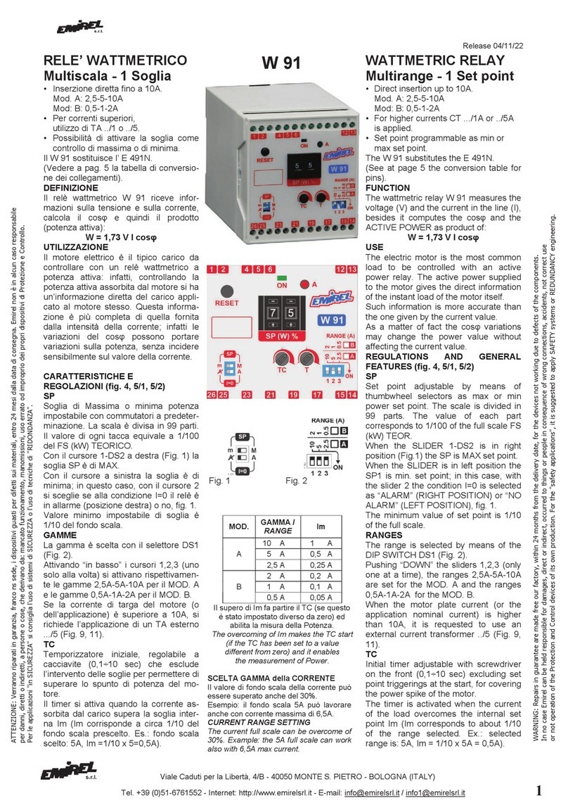
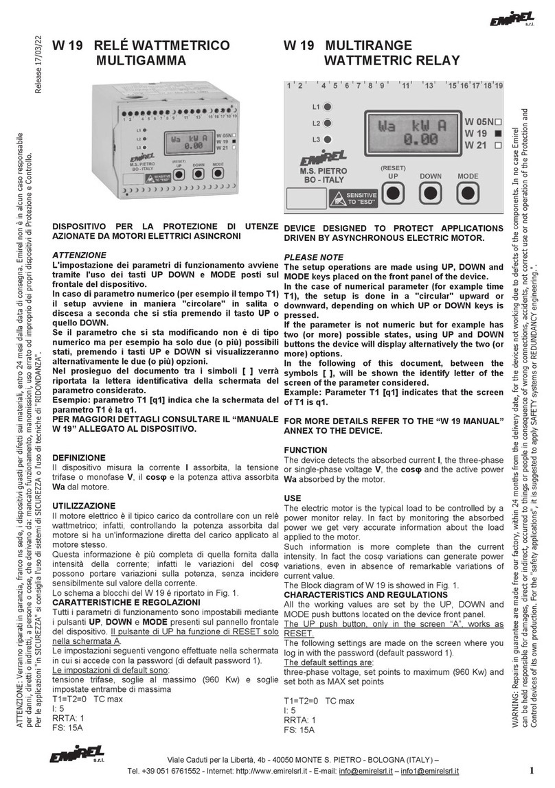
RELE’
DI SEQUENZA
FASI + ASIMMETRIA
RELE’ DI SEQUENZA
FASI
DEFINIZIONE
Nella versione A, il dispositivo controlla
l’esatta inserzione delle fasi L1, L2, L3
sui morsetti 4, 6, 8, rileva la mancanza
di una fase se la ‘’tensione di ritorno’’
generata dal motore è minore dell’85%
della tensione nominale.
Nella versione B controlla solo l’esatta
inserzione delle fasi.
VISUALIZZAZIONI
LED “G” é acceso se il dispositivo é
alimenta to e la sequenza delle fasi é
conforme alla denominazione dei
morsetti.
FUNZIONAMENTO (Fig. 3)
Versione A
• Il relè ed il led sono ON se la
sequenza delle fasi ai morsetti 4, 6, 8 è
L1, L2, L3 e se nessuna fase é
inferiore all’85% delle altre fasi.
• Il relè ed il led sono OFF se la
sequenza delle fasi ai morsetti 4, 6, 8
non é L1, L2, L3 e se una fase é
minore dell’85% delle altre.
Versione B
• Il relè ed il led sono ON se la
sequenza delle fasi ai morsetti 4, 6, 8 è
L1, L2, L3.
• Il relè ed il led sono OFF se la
sequenza delle fasi ai morsetti 4, 6, 8
non é L1, L2, L3.
RIPRISTINO
• per il modello B: automatico
quando la sequenza delle fasi è
corretta.
• per il modello A: automatico
quando l’asimmetria é minore del 10%.
SICUREZZA INTRINSECA
Con la sequenza L1, L2, L3 il relè è
ON.
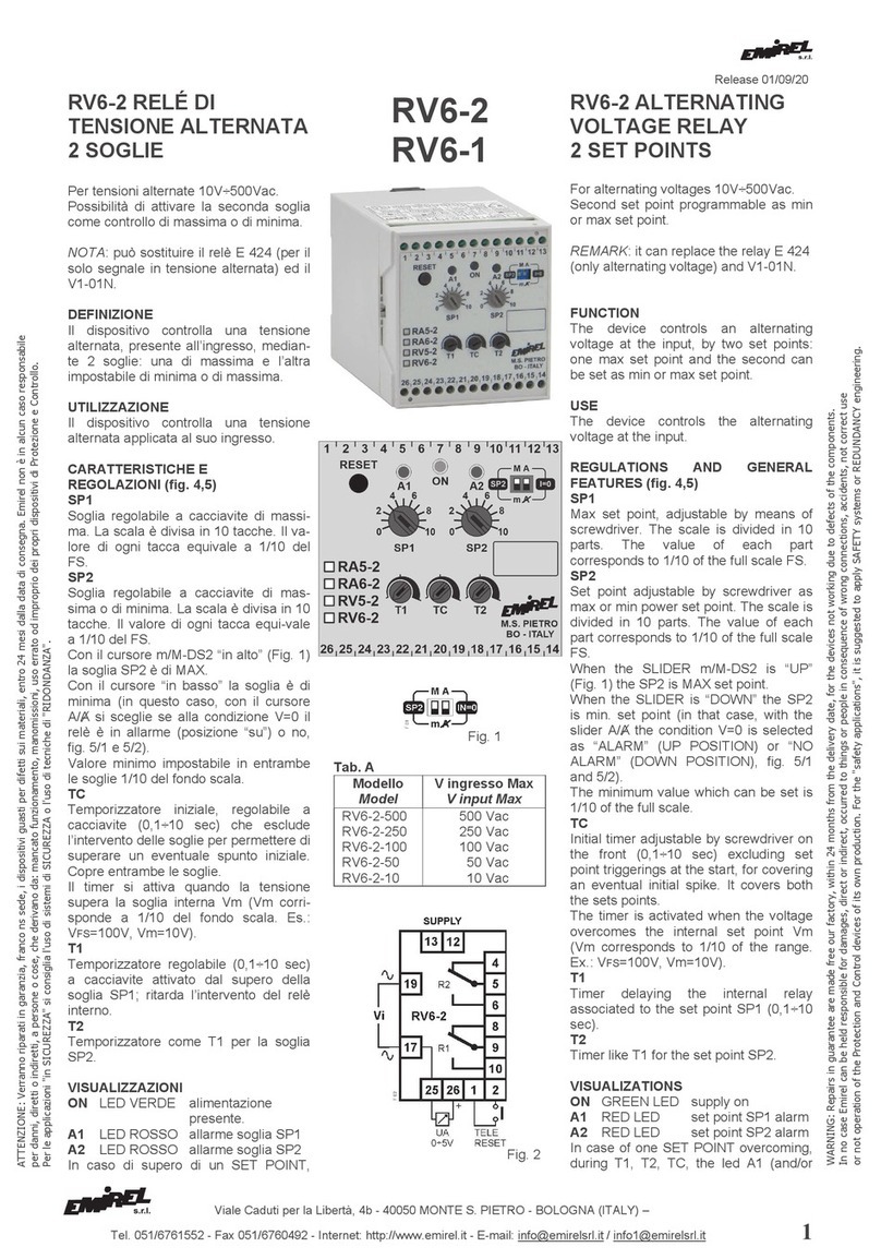
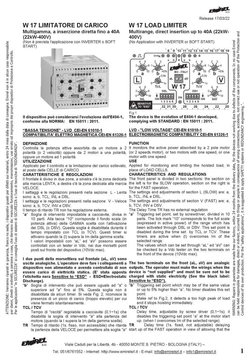
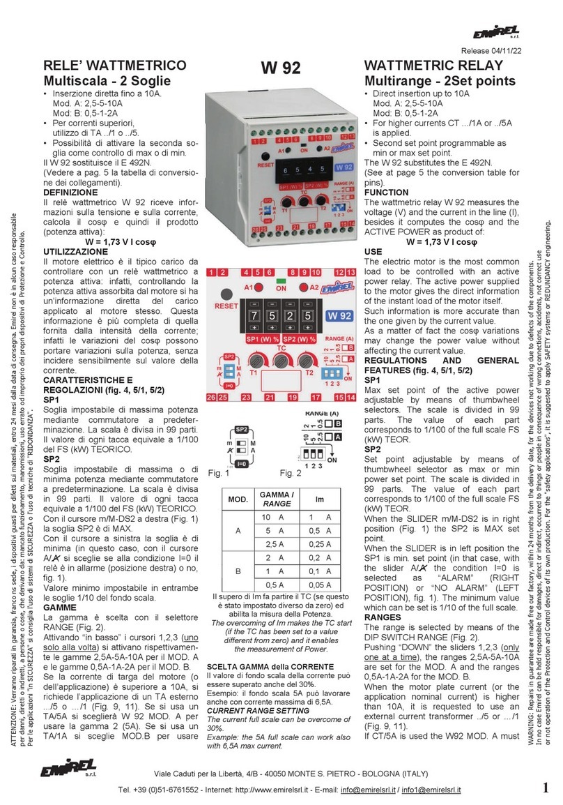
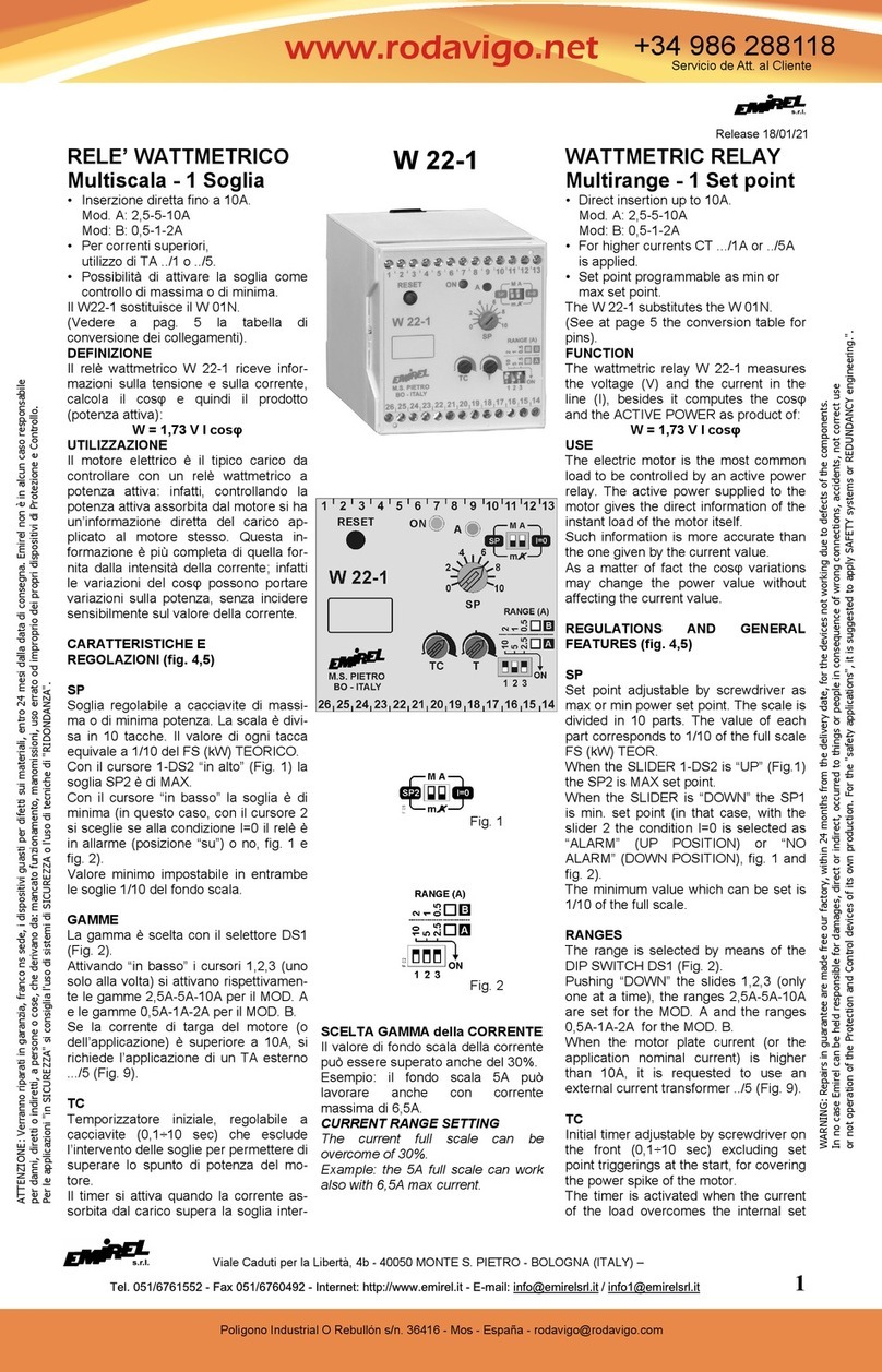
V3-12-A
V3-12-B
PHASES SEQ
UENCE
RELAY + ASYMMETRY
PHASES
SEQUENCE
RELAY
FUNCTION
In the model A, the device monitors the
correct phase sequence L1, L2, L3 on
the pins 4, 6, 8, and it detects the
phase failure if the back voltage
generated by the motor is lower than
85% of the nominal voltage.
In the model B, the device monitors the
correct phase sequence.
VISUALIZATIONS
LED “G” is on if the device is supplied
and the phase sequence complies with
the pin numbers.
MODE OF OPERATION (Fig. 3)
Model A
• The relay and the led are ON if the
phase sequence at the pins 4, 6, 8 is
L1, L2, L3 and if no phase is lower
than 85% of the other phases.
• The relay and the led are OFF if
the phase sequence at the pins 4, 6, 8
is not L1, L2, L3 or if one phase is
lower than 85% of the other phases.
Model B
• The relay and the led are ON if the
phase sequence at the pins 4, 6, 8 is
L1, L2, L3.
• The relay and the led are OFF if
the phase sequence at the pins 4, 6, 8
is not L1, L2, L3.
RESET
• Model B: automatic when the
phase sequence is correct.
• Model A: automatic when the
asymmetry is lower than
10%.
POSITIVE SAFETY
With L1, L2, L3 sequence the relay is
ON.
ATTENZIONE: Ve
rranno riparati in garanzia, franco ns sede, i dispositivi guasti per difetti sui materiali, entro
24
mesi dalla data di consegna. Emirel non è in alcun caso responsabile
per danni, diretti o indiretti, a persone o cose, che derivano da: mancato funzionamento, manomissioni, uso errato od improprio dei propri dispositivi di Protezione e Controllo.
Per le applicazioni "in SICUREZZA" si consiglia l'uso di sistemi di SICUREZZA o l'uso di tecniche di "RIDONDANZA".
WARNING: Repairs in guarantee are made free o
ur factory, within
24
months from the delivery date, for the devices not working due to defects of the components. In no case Emirel
can be held responsible for damages, direct or indirect, occurred to things or people in consequence of wrong connections, accidents, not correct use or not operation of the Protection and
Control devices of its own production. For the "safety applications", it is suggested to apply SAFETY systems or REDUNDANCY engineering.".

Viale Caduti per la Libertà, 4b - 40050 MONTE S. PIETRO - BOLOGNA (ITALY) –
2 Tel. 051/6761552 - Fax 051/6760492 - Internet: http://www.emirel.it - E-mail: info@emirelsrl.it – info1@emirelsrl.it
INSTALLAZIONE
Il V3-12 va inserito a monte del
teleruttore del motore (vedere fig.1 o
fig.2). Dopo aver collegato il motore
alla linea trifase in modo da avere il
senso di rotazione voluto, collegare il
dispositivo in modo che il led giallo sia
acceso. Se V3-12 viene installato a
valle di un interruttore generale, tutta la
rete alimentata da detto interruttore
risulterà protetta.
(Collegamento a un quadro elettrico
con differenziale e sezionatore).
La lunghezza di ogni collegamento
deve essere < 30m.
Il dispositivo deve essere installato
a fondo quadro elettrico a valle
dell’interruttore generale fuori dalla
portata dell’operatore.
INGRESSI
Ring = 2 MΩ
4, 6, 8 (V max 750V)
Sugli ingressi 6 e 8 sono stati impiegati
condensatori “X2”, e questo permette
di non dover usare fusibili di protezione
(EN 60335-1)
USCITA: v. Fig.1 e Fig 2 o TAB A.
COLLEGAMENTI
a vite, sezione max filo flessibile
2,5mm2.
Morsetti (M+F) a connettore per gli
ingressi 4-6-8; morsetti fissi per il
contatto del relè.
ALIMENTAZIONE: 2VA - 50÷60 Hz
autoalimentato dalla rete controllata.
TEMP. DI FUNZIONAMENTO
- 20°C ÷ +70°C
DIMENSIONI
1Modulo 17,5x90x80 mm per DIN
GAMMA DI LAVORO
Vedere TAB. A.
PESO: kg 0,150 COLORE: grigio
Nota generale: Negli schemi di
collegamento non sono riportati i fusibili
sulle alimentazioni e sugli ingressi
voltmetrici. I collegamenti elettrici
devono essere eseguiti a dispositivo e
quadro elettr
ico spenti.
COMPATIBILITA' ELETTRO
MAGNETICA
Electromagnetic compatibility
CEI-EN 61326-1
“BASSA TENSIONE” - LVD
LVD – “LOW VOLTAGE”
CEI-EN 61010-1
INSTALLATION
The device V3-12 is installed upstream
the motor contactor (see fig. 1 or fig.
2).
Install the motor according with the
requested correct rotation, connect the
device with the 3phase feed line in
such a way that the yellow led lights
on. If V3-12 is installed downstream
the general switch, the whole network
supplied by this switch will be
protected.
(Wiring to an electrical board with a
differential relay and a sectionalizing
switch).
The length of every wiring must be less
than 30m.
The device must be installed on the
bottom of the electrical cabinet
downstream the general switch, out
of the reach of the operator.
INPUTS
Input Resistance = 2 MΩ
4, 6, 8 (V max 750V)
On the inputs 6 and 8 the capacitors
“X2”, have been applied, so that it is
not necessary to apply the protection
fuses (EN 60335-1)
OUTPUT: see Fig.1 e Fig 2 or TAB A.
CONNECTIONS
Screw terminals for flexible cables up
to 2,5mm2.
Connector terminals (M+F) for the
inputs 4-6-8; fixed terminals for the
internal relay contact.
SUPPLY: 2VA - 50÷60 Hz
self-supplied by the monitored mains.
WORKING TEMPERATURE
- 20°C ÷ +70°C
DIMENSIONS
1 Module 17,5x90x80 mm DIN rail
RANGES
See TAB. A.
WEIGHT: kg 0,150 COLOUR: grey
Per la pulizia usare un panno imbevuto
di detergenti privi di: Alcool denaturato,
Benzene, Alcool isopropilico.
For cleaning use a cloth soaked with
detergents without: Denatured Alcohol,
Benzene, Isopropyl alcohol.
General remark: The wiring diagrams
do not show the fuses installed on the
supply and on the voltmetric inputs.
The electric wirings must be realized
with device and electrical panel in off
condition.
This manual suits for next models
2
Other Emirel Relay manuals
