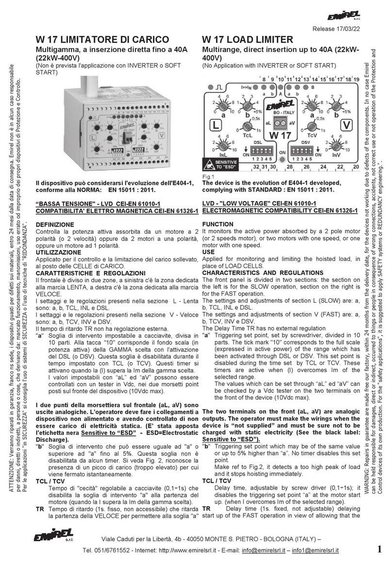
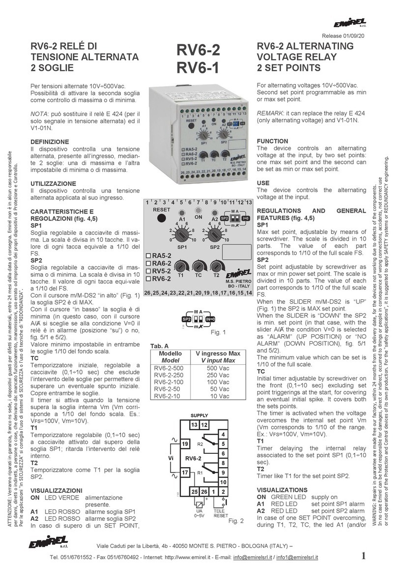
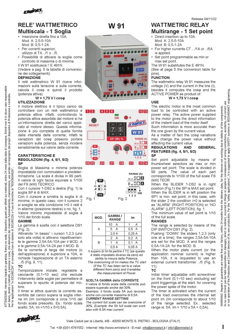
Emirel W 19 User manual

Viale Caduti per la Libertà, 4b - 40050 MONTE S. PIETRO - BOLOGNA (ITALY) –
Tel. +39 051 6761552 - Internet: http://www.emirelsrl.it - E-mail: inf[email protected] – info1@emirelsrl.it 1
W 19 RELÉ WATTMETRICO
MULTIGAMMA
DISPOSITIVO PER LA PROTEZIONE DI UTENZE
AZIONATE DA MOTORI ELETTRICI ASINCRONI
ATTENZIONE
L'impostazione dei parametri di funzionamento avviene
tramite l'uso dei tasti UP DOWN e MODE posti sul
frontale del dispositivo.
In caso di parametro numerico (per esempio il tempo T1)
il setup avviene in maniera "circolare" in salita o
discesa a seconda che si stia premendo il tasto UP o
quello DOWN.
Se il parametro che si sta modificando non è di tipo
numerico ma per esempio ha solo due (o più) possibili
stati, premendo i tasti UP e DOWN si visualizzeranno
alternativamente le due (o più) opzioni.
Nel prosieguo del documento tra i simboli [ ] verrà
riportata la lettera identificativa della schermata del
parametro considerato.
Esempio: parametro T1 [q1] indica che la schermata del
parametro T1 è la q1.
PER MAGGIORI DETTAGLI CONSULTARE IL “MANUALE
W 19” ALLEGATO AL DISPOSITIVO.
DEFINIZIONE
Il dispositivo misura la corrente Iassorbita, la tensione
trifase o monofase V, il cosφ e la potenza attiva assorbita
Wa dal motore.
UTILIZZAZIONE
Il motore elettrico è il tipico carico da controllare con un relè
wattmetrico; infatti, controllando la potenza assorbita dal
motore si ha un'informazione diretta del carico applicato al
motore stesso.
Questa informazione è più completa di quella fornita dalla
intensità della corrente; infatti le variazioni del cosφ
possono portare variazioni sulla potenza, senza incidere
sensibilmente sul valore della corrente.
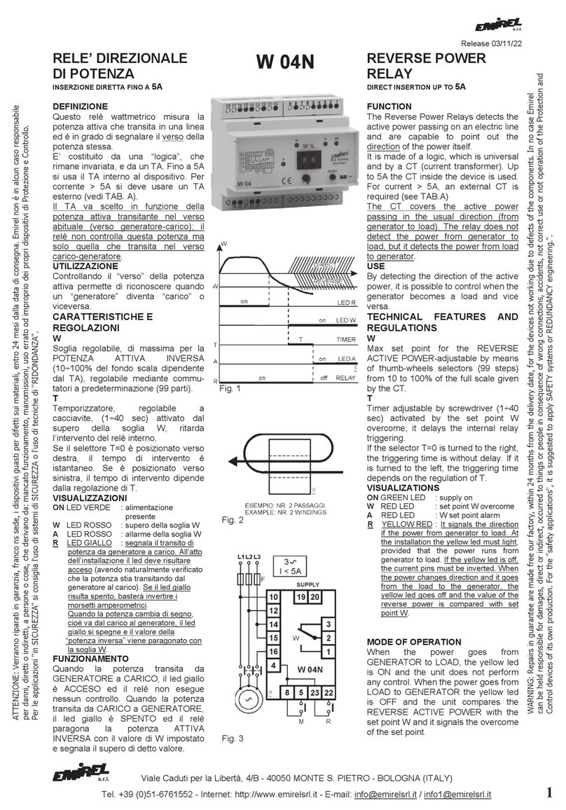
Lo schema a blocchi del W 19 é riportato in Fig. 1.
CARATTERISTICHE E REGOLAZIONI
Tutti i parametri di funzionamento sono impostabili mediante
i pulsanti UP, DOWN e MODE presenti sul pannello frontale
del dispositivo. Il pulsante di UP ha funzione di RESET solo
nella schermata A.
Le impostazioni seguenti vengono effettuate nella schermata
in cui si accede con la password (di default password 1).
Le impostazioni di default sono:
tensione trifase, soglie al massimo (960 Kw) e soglie
impostate entrambe di massima
T1=T2=0 TC max
I: 5
RRTA: 1
FS: 15A
W 19 MULTIRANGE
WATTMETRIC RELAY
DEVICE DESIGNED TO PROTECT APPLICATIONS
DRIVEN BY ASYNCHRONOUS ELECTRIC MOTOR.
PLEASE NOTE
The setup operations are made using UP, DOWN and
MODE keys placed on the front panel of the device.
In the case of numerical parameter (for example time
T1), the setup is done in a "circular" upward or
downward, depending on which UP or DOWN keys is
pressed.
If the parameter is not numeric but for example has
two (or more) possible states, using UP and DOWN
buttons the device will display alternatively the two (or
more) options.
In the following of this document, between the
symbols [ ], will be shown the identify letter of the
screen of the parameter considered.
Example: Parameter T1 [q1] indicates that the screen
of T1 is q1.
FOR MORE DETAILS REFER TO THE “W 19 MANUAL”
ANNEX TO THE DEVICE.
FUNCTION
The device detects the absorbed current I, the three-phase
or single-phase voltage V, the cosφ and the active power
Wa absorbed by the motor.
USE
The electric motor is the typical load to be controlled by a
power monitor relay. In fact by monitoring the absorbed
power we get very accurate information about the load
applied to the motor.
Such information is more complete than the current
intensity. In fact the cosφ variations can generate power
variations, even in absence of remarkable variations of
current value.
The Block diagram of W 19 is showed in Fig. 1.
CHARACTERISTICS AND REGULATIONS
All the working values are set by the UP, DOWN and
MODE push buttons located on the device front panel.
The UP push button, only in the screen “A”, works as
RESET.
The following settings are made on the screen where you
log in with the password (default password 1).
The default settings are:
three-phase voltage, set points to maximum (960 Kw) and
set both as MAX set points
T1=T2=0 TC max
I: 5
RRTA: 1
FS: 15A
ATTENZIONE: Verranno riparati in garanzia, franco ns sede, i dispositivi guasti per difetti sui materiali, entro 24 mesi dalla data di consegna. Emirel non è in alcun caso responsabile
per danni, diretti o indiretti, a persone o cose, che derivano da: mancato funzionamento, manomissioni, uso errato od improprio dei propri dispositivi di Protezione e Controllo.
Per le applicazioni "in SICUREZZA" si consiglia l'uso di sistemi di SICUREZZA o l'uso di tecniche di "RIDONDANZA". Release 17/03/22
WARNING: Repairs in guarantee are made free our factory, within 24 months from the delivery date, for the devices not working due to defects of the components. In no case Emirel
can be held responsible for damages, direct or indirect, occurred to things or people in consequence of wrong connections, accidents, not correct use or not operation of the Protection and
Control devices of its own production. For the "safety applications", it is suggested to apply SAFETY systems or REDUNDANCY engineering.".

Viale Caduti per la Libertà, 4b - 40050 MONTE S. PIETRO - BOLOGNA (ITALY) –
2Tel. + 39 051 6761552 - Internet: http://www.emirelsrl.it - E-mail: [email protected] – info1@emirelsrl.it
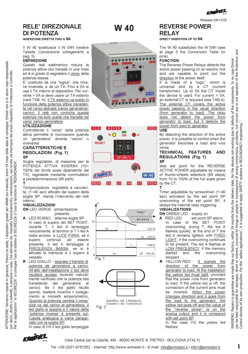
S1, S2 (s2) [SCH j e l]
Il dispositivo è dotato di due soglie di intervento (visibili sul
display LCD) impostabili con i tasti UP e DOWN, S1 è soglia
di MAX, S2 (s2) può essere di min (s2) o di MAX (S2) a
seconda della necessità.
La soglia S1 è collegata al relè A ed all’indicazione luminosa
1.
La soglia S2 (s2) è collegata al relè B ed all’indicazione
luminosa 2.
L’allarme delle soglie è visualizzato anche con un messag-
gio sulla schermata A.
L’intervento del relè A è ritardato del tempo T1.
L’intervento del relè B è ritardato del tempo T2.
Alla soglia s2 (impostata di minima) si può applicare la
funzione di allarme se la corrente è zero.
Questa funzione si attiva nella schermata d’impostazione
solo se la soglia è impostata di minima.
Se si sceglie s2 di minima, per la taratura, impostare la
soglia s2 a 0 Kw.
T1 [SCH q1]
Temporizzazione regolabile da 0 a 12 sec.
Ritarda l'intervento del relè di allarme A quando avviene il
supero della soglia S1.
T2 [SCH q2]
Temporizzazione regolabile da 0 a 12 sec.
Ritarda l'intervento del relè di allarme B quando avviene il
supero della soglia S2 (s2).
Tc (Tempo di cecità) [SCH q3]
Temporizzazione regolabile da 0 a 12 sec.
Esclude l'intervento di tutte le soglie di allarme per
permettere di superare lo spunto
di potenza del motore.
Questo timer si attiva quando la corrente assorbita dal carico
supera la soglia interna posta a 1/10 del fondo scala FS
scelto.
Il supero delle soglie S1 o S2 (s2) è segnalato
dall’accensione dei led 1 e/o 2.
Dopo il tempo T1 o T2 i relè Ao Bcambieranno di stato.
L’allarme può essere a ripristino manuale o automatico.
RRTA (V. TAB. A) [SCH a]
E’ variabile da 1 a 160.
Il parametro RRTA è il rapporto tra la corrente del primario
Ip e la corrente Is del secondario del TA esterno che può
essere necessario collegare (chiudendo il suo secondario
entro il TA del W 19).
In caso di inserzione diretta, RRTA=1.
Agendo sui pulsanti UP o DOWN sarà possibile impostare il
valore desiderato.
Per maggiore chiarezza circa l'impostazione del valore del
parametro RRTA consultare la tabella A.
Fig. 1
S1, S2 (s2) [SCR j and l]
The device is equipped with two set points (shown on the
front display). The set points are set by the UP and DOWN
push buttons. S1 is MAX set point, while S2 (s2) can be
set as MAX or min set point, on request.
The set point S1 is connected to the relay A and to the
light indication 1.
The set point S2 (s2) is connected to the relay B and to the
light indication 2.
The set points alarm is displayed also by a message on
“A” screen.
The relay A is delayed by time T1.
The relay B is delayed by time T2.
At the set point s2 (set as min set point) the alarm function
can be applied if the current is zero.
This function is activated in the setting screen only if the
set point is set as min set point.
If s2, set as min set point, is chosen, for the calibration, set
the set point s2 to 0 Kw.
T1 [SCR q1]
Timer adjustable from 0 to 12 sec.
It delays the relay alarm A triggering when the set point S1
is overcome.
T2 [SCR q2]
Timer adjustable from 0 to 12 sec.
It delays the relay alarm B triggering when the set point S2
(s2) is overcome.
Tc (Initial timer) [SCR q3]
Timer adjustable from 0 to 12 sec.
It excludes the set point triggerings in order to pass the
motor start up spikes. The timer is active when the current
in the load overcome the internal set point set at 1/10 of
the full scale FS selected.
The Led 1 and/or 2 light when the set point S1 or S2 (s2)
are overcome.
After the time delay T1 or T2 the relay Aor Bchanges
over.
The alarm can have manually or automatically reset.
RRTA (See TAB. A) [SCR a]
Adjustable form 1 to 160.
The value RRTA is the ratio between the current in the
primary Ip and the current Is of the secondary of the
external CT that may be required to connect to the internal
CT of W 19. In case of direct insertion RRTA=1
The required ratio is set by pressing the UP or DOWN
push buttons.
For better guidance in setting the value of RRTA, follow up
the indications of the table TAB. A.
Fig. 2

Viale Caduti per la Libertà, 4b - 40050 MONTE S. PIETRO - BOLOGNA (ITALY) –
Tel. +39 051 6761552 - Internet: http://www.emirelsrl.it - E-mail: inf[email protected] – info1@emirelsrl.it 3
N (V. TAB. A) [SCH b]
Impostazione variabile dei giri che vengono effettuati
all’interno del foro sul dispositivo se la corrente è < di 15A o
se si usa un TA esterno (per TA esterno impostare N=3)
N: 1÷15 [Fig. 2].
VISUALIZZAZIONI
LED
- Led 1rosso di superamento della soglia S1.
- Led 2rosso di allarme della soglia S2 (s2).
- Led 3|I| ha la seguente funzione:
acceso fisso indica la necessità di cambiare il fondo scala
di corrente (abbassarlo) o di aumentare i giri di filo di N.
DISPLAY LCD 2x8 RETROILLUMINATO
- Potenza attiva istantanea assorbita dal motore Wa (kW)
- Corrente assorbita I e tensione di linea V
- Parametri di impostazione (tempi e soglie)
- Messaggio di allarme di supero soglie.
FUNZIONAMENTO
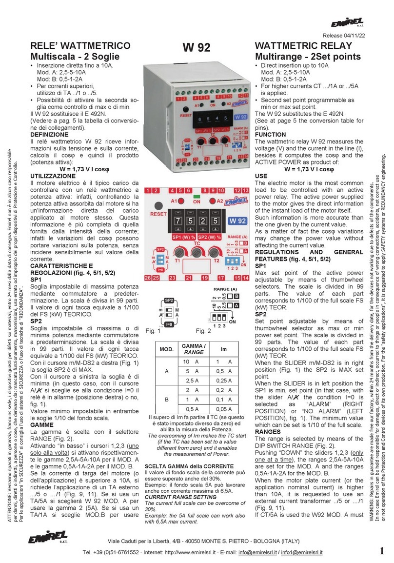
Il grafico di Fig. 3 illustra il funzionamento del W 19 in
funzione del valore delle soglie.
Le soglie di intervento S1,s2,saranno state impostate
manualmente (s2 è in questo caso soglia di intervento di
minima, perché indicata con la lettera minuscola - per
dettagli vedere descrizione schermata "l").
GAMME:
Valori disponibili: 15A, 25A, 40A, 60A, 80A da programmare.
La fase collegata al pin voltmetrico 15 è la fase ampero-
metrica e deve passare entro il foro (Ø=13mm) presente nel
W 19.
Esempio 1: Motore con IN=20A, il filo della fase passa 1
volta nel foro e nel programma si sceglierà la
GAMMA 25A ed RRTA=1.
Esempio 2: Motore con IN=110A, il valore è maggiore di
80A, serve un TA esterno, ad esempio 120/5
RRTA=120/5=24 (da inserire nel programma).
Si sceglierà la GAMMA 15A e il filo del secon-
dario del TA passerà 3 volte nel foro e si pro-
grammerà N=15/5=3.
Esempio 3: Motore con IN=3A, si sceglie la GAMMA: 15A, si
programma N=15/3=5 e la fase amperometrica
passa 5 volte nel foro (Ø=13mm).
N (See TAB. A) [SCH b]
Setting variable of wirings through the hole of the device if
the current is < of 15A or if an external CT is used (for
external CT set N = 3) N: 1÷15 [Fig. 2].
Legenda TAB. A
PMAX (Kw)= valore “pratico” di potenza del
motore trifase.
I (A)= valore da impostare (o da I targa o
derivata da WN).
FS = Fondo Scala selezionato del
W 19 (15-25-40-60-80A) [SCH c].
Im: corrente minima richiesta per attivare
il TC.
N = numero di passaggi del filo del
secondario del TA esterno entro il foro del
W 19.
TA = Riduttore di corrente.
RRTA = parametro da inserire nel W 19
RRTA=Ip/Is
Ip=IPRIM Is=ISEC
Legend TAB. A
PMAX (Kw)= “practical” value of power of
three-phase motor.
I (A) = value to set (or I plate or derived
from WN).
FS = Current full scale of the W 19 (15-
25-40-60-80A) [SCR c].
Im: minimum current requested to activate
the TC.
N = number of wire windings of the
secondary of the external CT through the
hole of the W 19.
CT = Current Transformer
RRTA = parameter to be
entered in the W 19.
RRTA=Ip/Is Ip=IPRIM Is=ISEC
VISUALIZATIONS
LED
- Led 1red refers to the overcoming of the set point S1.
- Led 2red refers to the alarm of the set point S2 (s2).
- Led 3|I| has the following function:
steady light it signals the need to change the full scale
of current (reduce it) or to increase the number of wire
windings (N).
DISPLAY LCD 2x8 back-lighted.
- Instant active power absorbed by the motor Wa (kW)
- Current I and line voltage V
- Set values (timers and set points)
- Alarm message referred to the overcoming of the set
points.
MODE OF OPERATION
The diagram in Fig. 3 shows the W 19 operation basing on
the set points.The set points S1, s2,are manually set (s2
in this case is minimum set point because it is identified by
a little letters make ref to the details in the shot screen “I”).
RANGES:
Available values: 15A, 25A, 40A, 60A, 80A to be set.
The phase connected with the voltmetric pin 15 is the
amperometric phase and it must enter into the hole
(Ø=13mm) present on the W 19.
Example 1: Motor with IN=20A, the phase wire passes 1
time into the hole and, in the programme,
the RANGE 25A and RRTA=1 must be
selected.
Example 2: Motor with IN=110A, the value is greater than
80A, an external CT must be used, for
example 120/5 RRTA=120/5=24 (to be set
in the programme).
The RANGE 15A must be selected and the
wire of the secondary of CT must pass in the
hole 3 times and N=15/5=3 must be set.
Example 3: Motor with IN=3A, the RANGE 15A must be
selected, N=15/3=5 must be set and the
amperometric phase passes in the hole
TAB. A
I (A)
Targa F.S. Im N TA / CT EST. RRTA
P MAX
( Cosj= 1
V = 4
0
0
Vac )
1 15 0,1A 15 – 1 0,69 KW
2,1 15 0,21A 7 – 1 1,45 KW
3 15
0,3A
5
–
1
2,07 KW
3,75 15 0,37A 4 – 1 2,59 KW
5 15 0,5A 3 – 1 3,46 KW
7,5 15 0,75A 2 – 1 5,19 KW
15 15 1,5A 1 – 1 10,4 KW
25 25 2,5A 1 – 1 17,3 KW
40 40 4,0A 1 – 1 27,7 KW
60 60 6,0A 1 – 1 41,5 KW
80 80 8,0A 1 – 1 55,4 KW
100 15 10,0A 3 100/5 20 69,2 KW
150 15 15A 3 150/5 30 103 KW
200 15 20A 3 200/5 40 138 KW
250 15
25A
3 250/5 50 173 KW
500 15
50A
3 500/5 100 346 KW
600 15 60A 3 600/5 120 415 KW
800 15 80A 3 800/5 160 553,6 KW

Viale Caduti per la Libertà, 4b - 40050 MONTE S. PIETRO - BOLOGNA (ITALY) –
4Tel. + 39 051 6761552 - Internet: http://www.emirelsrl.it - E-mail: [email protected] – info1@emirelsrl.it
Il dispositivo W 19
esegue la rilevazione
e la visualizzazione
della potenza attiva.
All'accensione del
motore il "picco" di
potenza viene
ignorato mediante
l'uso del TC.
A regime, l'intervento
delle soglie S1 ed S2
(s2) è ritardato,
indipendentemente,
con T1 e T2 (v. Fig.3).
Lo strumento resta
programmato anche
togliendo
l'alimentazione.
TARATURA (in modalità STANDARD)
SET POINT S1, S2 (s2) [SCH j e I]
Impostare i vari parametri (tensione, corrente I), eventuale
TA.
Fare andare a regime il motore e verificare l’assorbimento
(Wa) ed impostare le soglie ad un valore un po’ maggiore,
se di massima, ed un valore inferiore se s2 è di minima
oppure portare S1 e TC al massimo, T1, T2 al minimo e S2
al massimo se è programmata di MAX, a zero se è
programmata di min. Con il motore acceso e
opportunamente "caricato", abbassare la regolazione della
soglia S1 fino ad avere l'accensione del led 1e l'intervento
del dispositivo. A questo valore di soglia si dovranno
applicare delle correzioni che tengano conto delle condizioni
operative finali della macchina, della temperatura,
dell'invecchiamento ecc... ecc...
Spegnere il motore e riaccendere varie volte, riducendo ogni
volta il TC fino a trovare il valore per cui si ha subito
l'intervento.
A questo valore si dovranno apportare delle correzioni per le
stesse considerazioni fatte per la soglia S1.
Aumentare opportunamente il T1 per evitare interventi
intempestivi durante il funzionamento normale.
Se la soglia S2 è programmata di MAX, si dovrà seguire la
stessa procedura seguita per la soglia S1.
Se la soglia s2 è programmata di min: accendere il motore
“senza carico”, aumentare la regolazione della soglia s2 da
zero fino all’accensione del led 2; a questo valore applicare
delle correzioni per le considerazioni sopraddette.
Aumentare opportunamente T2.
RIPRISTINO [SCH k,n]
Le soglie di allarme S1 ed S2 (s2) sono impostate per
default a ripristino automatico.
Nelle schermate sopra indicate possono essere impostate a
ripristino manuale, indipendentemente l'una dall'altra,
scegliendo l’opzione “man”.
In questo caso, il ripristino avviene premendo il tasto UP
(RESET) quando la condizione di allarme viene a cessare (il
pulsante di reset è attivo solo nella schermata “A”) o usando
un contatto esterno collegato ai pin 18-19 o togliendo
momentaneamente l’alimentazione.
USCITE A RELE’
I due relè interni RA e RB sono “normalmente ON” (i contatti
di riposo sono chiusi) e andranno OFF in caso di allarme.
(Ø=13mm) 5 times.
The W 19 measures and
displays the active power.
At the motor start up the
power spike is covered
by the initial timer TC.
During the regular
operation the triggering of
set points S1 and S2 (s2)
is delayed with T1 and T2
respectively (see Fig.3)
Also after the voltage
supply is cut off the
device remains
programmed.
SETTING (in STANDARD mode operation)
S1, S2 (s2) SET POINTS [SCR j e l]
Set the several parameters (voltage, current I), possible
CT.
Run the motor at full speed and check the absorption (Wa)
and set the set points to a slightly higher value, if set as
MAX, and to a lower value if s2 is set as min set point or
set S1 and TC to the maximum, T1 and T2 to the
minimum; S2 to the maximum if it is set as maximum set
point, to zero (s2) if it is set as minimum set point (TC is
active or not depending on the applications).
With motor supplied and opportunely loaded, lower the S1
value until the led 1lights on.
The reached value has to be rectified conveniently in order
to consider the age of the machine, the temperature and
working conditions etc.
Stop the motor and start it up again several times gradually
reducing each time the initial timer TC until reaching the
value where the device triggers promptly.
This value shall have to be rectified conveniently for the
same reasons explained above for S1.
Timer T1 shall have to be increased for avoiding wrong
alarms during regular operation.
If S2 is set as max set point, follow the same setting
procedure adopted for S1.
If s2 is set as min set point, the following procedure must
be adopted.
Start up the motor without load; increase the s2 set point
regulation until the led 2lights on.
Increase opportunely the Timer T2.
RESET [SCR k,n]
The set points S1 and S2 (s2) are set by default with
automatic reset.
These can be programmed in manual mode independently
one from each other selecting “man”.
In this case the reset takes place by pressing the UP
(RESET) push-button when the alarm condition stops (the
reset key is active only in the “A” screen) or by using an
external contact connected to pins 18-19 or by removing
the supply temporarily.
RELAY OUTPUT
The two internal relays RA and RB are “normally ON” (the
NC contacts are closed) and they will go “OFF” in case of
alarm.
Fig. 3

Viale Caduti per la Libertà, 4b - 40050 MONTE S. PIETRO - BOLOGNA (ITALY) –
Tel. +39 051 6761552 - Internet: http://www.emirelsrl.it - E-mail: inf[email protected] – info1@emirelsrl.it 5
USCITA ANALOGICA
Ai pin 17-18 (+ sul pin 17) è disponibile una tensione 0-10
Vdc fondo scala (max 1mA) proporzionale alla potenza
attiva istantanea Wa assorbita. Si consiglia di utilizzare un
VOLTMETRO DC DVD 08, con possibilità di calibratura, per
poter visualizzare "100" o il valore che si legge sul display
del W 19 in condizione di normale funzionamento (scherma-
ta A).
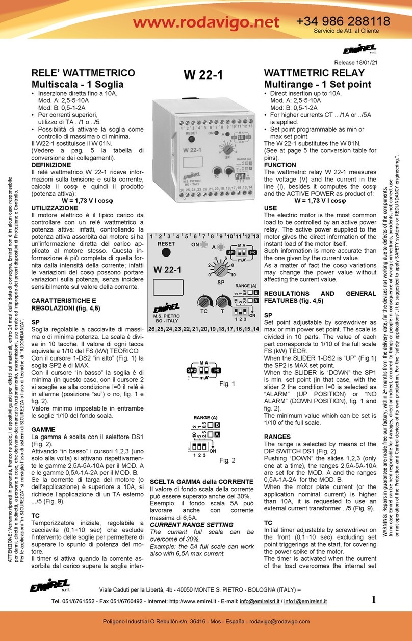
COLLEGAMENTI ELETTRICI
Collegamenti a vite sul frontale da eseguire secondo schemi
di fig. 4-5 (motore trifase) o fig. 6-7 (motore monofase). Per
la scelta del TA vedere il paragrafo inerente il parametro
RRTA.
(Collegamento a un quadro elettrico con differenziale e
sezionatore). La lunghezza di ogni collegamento deve
essere < 30m.
ESEMPI DI COLLEGAMENTI
1. TRIFASE I < 80A: inserzione diretta
Seguire lo schema di fig. 4
pin voltmetrici: 15-13-11
2. TRIFASE I > 80A: con TA.. /5
Seguire lo schema di fig. 5
pin voltmetrici: 15-13-11
3. MONOFASE I < 80A: Inserzione diretta
Seguire lo schema di fig. 6
pin voltmetrici: 15-16
4. MONOFASE I > 80A: inserzione con TA.. /5
Seguire lo schema di fig. 7.
pin voltmetrici: 15-16
NOTA 3: La fase di cui si misura la corrente (fase
amperometrica, nelle figure 4, 5, 6 e 7 è la L1) deve essere
collegata all'ingresso voltmetrico 15.
Per utilizzare correttamente un W 19 occorre determinare i
seguenti elementi del motore: [vedere targa motore]
1) Tensione di alimentazione del motore (400 Vac ecc.)
2) Potenza nominale del motore WN o Corrente di targa
del motore I
Fig. 4
NOTA: Il dispositivo è utilizzabile con motori trifase o
monofase, motore da 415 VAC.
ANALOG OUTPUT
At the pins 17-18 (+ on pin 17) the voltage 0-10Vdc full
scale (max 1mA) is available.
The 0-10 Vdc signal is proportional to the instant active
power Wa measured. It is suggested to apply a DC
VOLTMETER DVD 08, with calibration of the reading, in
order to display "100" or the value appearing on the
display of W 19 during normal operation (“A” screen).
WIRING DIAGRAMS
Screw connections on the front to be made as per fig. 4-5
(three-phase motor) or fig. 6-7 (single phase motor).
For the CT's selection see the paragraph referring to the
parameter RRTA.
(Wiring to an electrical board with a differential relay and a
sectionalizing switch). The length of every wiring must be
less than 30m.
EXAMPLES OF CONNECTIONS
1. THREEPHASE I < 80A: direct insertion
Follow diagram of fig. 4
Voltage pins : 15-13-11
2. THREEPHASE I > 80A: Connection by CT ../5
Follow diagram of fig. 5
Voltage pins : 15-13-11
3. SINGLE PHASE I < 80A: Direct insertion
Follow diagram of fig. 6
Voltage pins: 15-16
4. SINGLE PHASE I > 80A: Direct insertion by CT.. /5
Follow diagram of fig. 7.
Voltage pins: 15-16
REMARK 3:
The phase carrying the measured current (amperometric
phase L1 in the figures 4, 5, 6 and 7) must be connected to
voltage pin 15.
For a correct application of the W 19 the following motor
elements must be correctly identified: [see the motor plate]
1) Motor Voltage (400 Vac etc.)
2) Rated power WN or Rated current I
Fig. 5
REMARK: The device can be used for three-phase or
single phase motors, motor at 415 VAC.
NOTA:
Il TA esterno dovrebbe
avere una
PRESTAZIONE ≥ 5VA
per rispettare il
FATTORE DI POTENZA.
REMARK:
The external CT must
have the BURDEN ≥ 5VA
to not modify the
POWER FACTOR.

Viale Caduti per la Libertà, 4b - 40050 MONTE S. PIETRO - BOLOGNA (ITALY) –
6Tel. + 39 051 6761552 - Internet: http://www.emirelsrl.it - E-mail: [email protected] – info1@emirelsrl.it
Fig. 6
INGRESSI
Ring = 800 kW
PIN Voltmetrici: 15-13-11 (Vedere Nota 3).
Massima tensione trifase 415 Vac.
Per tensioni maggiori di 400 Vac è necessario usare M 08:
resistenza di caduta trifase (Ved. Fig. 8).
Su W 19 inserire VNdel motore.
Es. Motore da 480V M 08 480/400 e nel W 19 impostare
VN=480V.
Corrente di misura: diretta fino a 80A, per correnti superiori
è necessario un TA esterno .../5. Si consiglia l’utilizzo di TA
di classe 0,5.
USCITE
RELE’ 5A (NA) 230 Vac, carico resistivo
“a1” 8-9 NA
8-7 NC Dispositivo non
“b1” 5-6 NA alimentato
5-4 NC
ALIMENTAZIONE: 24 Vac o 230 Vac monotensione
6VA 50-60Hz ±10% pin 1-2
DIMENSIONI: 100x70x110 mm x GUIDA DIN.
Accessori (a richiesta): E 405A protezione trasparente
piombabile.
TEMPERATURA DI FUNZIONAMENTO: 0÷70°C
PESO: Kg 0,550 COLORE: grigio
NOTA IMPORTANTE
Si consiglia di non posizionare, in prossimità del W 19 e dei
suoi cavi di collegamento, dei dispositivi che possano creare
disturbi come teleruttori, inverter ecc... I teleruttori è
opportuno vengano sempre dotati degli appositi snubber
(collegati alla bobina del teleruttore).
MISURE DI SICUREZZA
Il dispositivo DEVE essere installato esclusivamente all’interno di un
quadro elettrico chiuso mediante chiave o dispositivo analogo.
L’accesso al suddetto quadro e di conseguenza al dispositivo,
DEVE essere effettuato esclusivamente a quadro disalimentato e
SOLO dal personale di manutenzione o di installazione
opportunatamente formato ed addestrato alla operazione prevista.
Per la pulizia usare un panno imbevuto di detergenti privi di: Alcool
denaturato, Benzene, Alcool isopropilico.
COMPATIBILITA' ELETTRO
MAGNETICA
Electromagnetic compatibility
CEI
-
EN 61326
-
1
“BASSA TENSIONE” - LVD
LVD – “LOW VOLTAGE”
CEI-EN 61010-1
Fig. 7
Fig. 8
INPUTS
Input Resistance = 800 kW
Voltage pins: 15-13-11 (See Remark 3).
Maximum threephase voltage is 415 Vac.
For higher voltages is requested the application of M 08:
Threephase drop resistances (see Fig. 8).
In the W 19 set VN of the motor.
Ex. 480V Motor M 08 480/400 and in the W 19 set
VN=480V.
Current range: direct up to 80A, with external CT .../5 for
current higher than 80A. The use of CT with range 0.5 is
recommended.
OUTPUTS
RELAYS 5A (NO) 230 Vac, resistive load
“a1” 8-9 NO
8-7 NC Device not
“b1” 5-6 NO supplied
5-4 NC
SUPPLY: 24 Vac or 230 Vac single voltage
6VA 50-60 Hz ±10% pin 1-2
DIMENSIONS: 100x70x110 mm Din Rail
Accessories (on request): E 405A transparent cover for
tight closure.
WORKING TEMPERATURE: 0÷70°C
WEIGHT: Kg 0,550 COLOUR: grey
IMPORTANT REMARK
Please do not place close to the W 19 and its connection
cables some devices that might create disturbances such
as contactors, inverters and so on...
The contactors should be equipped with appropriate
snubber (on the contactor coil).
SECURITY MEASURES
The device MUST be installed only inside an electrical panel
closed by a key or similar device.
Access to this electrical panel and consequently at the device,
MUST be done exclusively with panel switched off and ONLY by
maintenance or installation personnel suitably formed and trained
for the planned operation.
For cleaning use a cloth soaked with detergents without:
Denatured Alcohol, Benzene, Isopropyl alcohol.

Viale Caduti per la Libertà, 4b - 40050 MONTE S. PIETRO - BOLOGNA (ITALY) –
Tel. +39 051 6761552 - Internet: http://www.emirelsrl.it - E-mail: inf[email protected] – info1@emirelsrl.it 7
W19 RELE’ WATTMETRICO
IMPOSTAZIONE PARAMETRI DI FUNZIONAMENTO
Mediante tasti UP e DOWN presenti sul frontale del dispositivo inserire i valori dei parametri
Mediante il tasto MODE spostarsi di schermata in schermata
Di seguito è riportata la successione delle schermate di visualizzazione e impostazione del dispositivo e il loro funzionamento:
W a k W A
x x x . x x
Schermata di visualizzazione della potenza assorbita dal carico
c o s φ C
x . x x
Schermata di visualizzazione del cos φ
V = x x x V
I = x x x . x A
Schermata di visualizzazione della tensione di linea V e della
corrente I assorbita dal motore
P W D E
p w d = x x x
Schermata di inserimento password per poter accedere al menù di
configurazione dei parametri di funzionamento
S E T a
R R T A = x x x
Rapporto di trasformazione dell’ eventuale TA esterno
1 < RRTA < 160
Se non c’è TA esterno RRTA=1
Esempio: se si usa un TA 100/5 impostare RRTA=20
S E T b
N = 1-2-3-4-5..15
Schermata di inserimento numero di passaggi del cavo di corrente
all'interno del TA del W19.
In caso di TA esterno, tipicamente, N=3.
Nota: quando N > 1 automaticamente si ha FS=15
S E T
c
F S = 1 5 A
S
E
T
c
F S = 2 5 A
S E T c
F S = 4 0 A
S E T c
F S = 6 0 A
S E T c
F S = 8 0 A
In questa schermata viene impostato il valore di fondo scala di
funzionamento del dispositivo.
Le soglie di allarme sono dipendenti dal valore di fondo scala
impostato.
E’ necessario scegliere il fondo scala più appropriato in funzione
della taglia del motore.
In caso di utilizzo di un TA esterno viene automaticamente
selezionato FS=15. Per una maggiore precisione è opportuno fare
3 passaggi del filo del secondario del TA esterno all'interno del TA
dell'W19(ovviamente impostando poi N=3 nell'apposita
schermata)
NOTA IMPORTANTE: Sul frontale del dispositivo è presente un
led di segnalazione con il simbolo |I|.
L'accensione di questo LED avvisa l'utilizzatore che non ha
selezionato il fondo scala di corrente più corretto.
ESEMPIO: FS=60 e IN=5A. In questo caso il led (giallo) |I| sarà
acceso e le varie misure di potenza-corrente e cosφ saranno zero.
S E T d
n ° F =
3
1
Schermata che consente la scelta del tipo di motore, trifase (3) o
monofase (1)
S E T A g
I N = x x x . x
Schermata di inserimento della corrente di targa IN del motore.
Il valore di default è 5.0A.
0.1 < IN < 800 A
Premendo contemporaneamente UP e DOWN il valore
incrementerà di 10 Ampere
S E T i
V N = x x x V
Il valore di default è 400 Vac.
Per tensioni di linea < 415 Vac non modificare il valore di default.
Per tensioni maggiori di 415 Vac inserire il valore della tensione di
linea reale a monte dell’adattatore di tensione M08 (che dovrà
avere tensione sul secondario pari a 400 Vac.

Viale Caduti per la Libertà, 4b - 40050 MONTE S. PIETRO - BOLOGNA (ITALY) –
8Tel. + 39 051 6761552 - Internet: http://www.emirelsrl.it - E-mail: [email protected] – info1@emirelsrl.it
ESEMPIO: per una tensione di linea di 600 Vac useremo un M08-3
(600/400 Vac) e imposteremo VN=600 Vac
S E T S 1 j
x x x . x k W
Schermata di setup della soglia di intervento di MAX S1
s2 < S1 < 960kW (se s2 soglia di min)
0.0 < S1 < 960kW (se S2 soglia di MAX)
Premendo contemporaneamente i tasti UP e DOWN si setterà
S1=(IN/2) kW in modo da velocizzare le operazioni di setup
S E T k
S 1 = a u t
m a n
Schermata di selezione del modo di ripristino della soglia S1
(automatico o manuale)
S E T S 2 l
s
x x x . x k W
Schermata di setup della soglia di intervento di min/MAX S2
0.0 < s2 < S1 (se s2 soglia di min)
0.0 < S2 < 960kW (se S2 soglia di MAX)
S2= soglia 2 impostata come soglia di MAX
s2= soglia 2 impostata come soglia di min
Premendo contemporaneamente i tasti UP e DOWN si setterà
S2=(IN/2) kW in modo da velocizzare le operazioni di setup
S E T m
S 2 = m i n
M A X
Schermata di selezione “soglia di MAX” S2 o “soglia di min” di s2
S E T n
S 2 = a u t
m a n
Schermata di selezione del modo di ripristino della soglia S2
(automatico o manuale)
S E T I = 0
A L O F F
O N
Schermata di inserimento condizione di allarme in caso di I=0
quando la soglia s2 è impostata come soglia di “min”
S E T q 1
T 1 = x x x s
Tempo di allarme T1 della soglia S1
0.1 < T1 < 12 sec
S E T q 2
T 2 = x x x s
Tempo di allarme T2 della soglia S2
0.1 < T2 < 12 sec
S E T q 3
T c = x x x s
Tempo di cecità allo spunto del dispositivo
0.1 < Tc < 12 sec
S E T v
p w d = x x x
Schermata di inserimento e memorizzazione della password che
deve essere inserita nella schermata “E” se si vuole entrare nel
menù di configurazione dei parametri di funzionamento.
Di default pwd = 001
S E T w
E N D
Schermata di fine SETUP

Viale Caduti per la Libertà, 4b - 40050 MONTE S. PIETRO - BOLOGNA (ITALY) –
Tel. +39 051 6761552 - Internet: http://www.emirelsrl.it - E-mail: inf[email protected] – info1@emirelsrl.it 9
W19 WATTMETRIC RELAY
SETTING FUNCTIONING PARAMETERS
Using UP and DOWN keys on the front panel of the device to set the parameters
Using MODE key to change screen.
The following is a description of the operation of each device window.
W a k W A
x
x
x
.
x
x
Active power Wa
c o s φ C
x . x x
Cos φ
V = x x x V
I = x x x . x A
Line voltage V and the absorbed current I
P W D E
p w d = x x x
Entry screen to entering password in order to access the
configuration menu of the operating parameters
S E T a
R R T A = x x x
Transformation ratio of the external CT
1 < RRTA < 160
In case of no external CT RRTA=1
Example: if a 100/5 CT is needed, set RRTA=20
S E T b
N = 1-2-3-4-5..15
Number of wiring inside the W19 CT
In case of external CT, typically, N=3.
Note: when N > 1 automatically is selected FS=15 A
S E T c
F S = 1 5 A
S E T c
F S = 2 5 A
S E T
c
F S = 4 0 A
S E T
c
F S = 6 0 A
S E T
c
F S = 8 0 A
Full Scale FS of the device.
There are five different FS value:
FS=15 A
FS=25 A
FS=40 A
FS=60 A
FS=80 A
That choice must be made in according to the nominal power WN
of the motor.
All the set points are depending from the set FS value .
In case of use of an external CT (RRTA parameter > 1) FS=15 A is
automatically selected by software.
For a better accuracy and if the external CT is a xx/5 CT, the user
should make three wiring into the W19 CT and set N=3 in the “b”
screenshot.
VERY IMPORTANT: On the front of the device there is a yellow
led called |I|.
The fixed lighting of this LED alerts the user that it has selected
the wrong FS value.
EXAMPLE: FS=60 and IN=5A. In this case the led |I| will be
lighted and all the measures will be zero.
S E T d
n ° F =
3
1
Type of motor: three-phase (3) or single-phase (1) motor
S E T A g
I N = x x x . x
Entry screen of the motor rated current IN.
The default value is 5.0A
0.1 < IN < 800 A
Pressing UP e DOWN at the same time the value will rise by 10
Ampere
S E T i
V
N
=
x
x
x
V
The default value is 400 Vac.
For line voltages < 415 Vac do not change the default value.
For line voltages > 415 Vac, enter the actual line voltage value.
EXAMPLE: For a 600 Vac line voltage we will use an M08-3
(600/400 Vac) and set VN = 600 Vac

Viale Caduti per la Libertà, 4b - 40050 MONTE S. PIETRO - BOLOGNA (ITALY) –
10 Tel. + 39 051 6761552 - Internet: http://www.emirelsrl.it - E-mail: [email protected]t – info1@emirelsrl.it
S E T S 1 j
x x x . x k W
Set point S1 (MAX)
s2 < S1 < 350kW (if s2 is set as min)
0.0 < S1 < 350kW (if S2 is set as MAX)
Pressing the UP and DOWN keys simultaneously will be set
S1 = (IN / 2) kW in order to speed up the setup operations.
S
E
T
k
S 1 = a u t
m a n
Reset mode of set point S1
S1= aut : automatic reset
S1= man : manual reset
S E T S 2 l
s
x x x . x k W
Set point S2 (s2)
0.0 < s2 < S1 (if s2 is set as min)
0.0 < S2 < 350kW (if S2 is set as MAX)
S2= set point S2 set as a maximum set point
s2= set point s2 set as minimum set point.
Pressing the UP and DOWN keys simultaneously will be set
S1 = (IN / 2) kW in order to speed up the setup operations.
S E T m
S 2 = m i n
M
A
X
S2= MAX : set point S2 set as a maximum set point
s2= min : set point s2 set as minimum set point.
S E T n
S 2 = a u t
m a n
Reset mode of set point S2
S2 (s2)= aut : automatic reset
S2 (s2)= man : manual reset
S E T I = 0
A L O F F
O N
Alarm condition input screen in case of I = 0 if threshold s2 is set
as MIN threshold
S E T q 1
T 1 = x x x s
Time delay T1 of S1 set point
0.1 < T1 < 12 sec
S E T q 2
T 2 = x x x s
Time delay T2 of S2 set point
0.1 < T2 < 12 sec
S E T q 3
T c = x x x s
Time delay Tc to deactivate the set points in order to pass the
motor start
0.1 < Tc < 12 sec
S E T v
p w d = x x x
Input screen of the PASSWORD pwd of the system.
000 < pwd < 999
The default value is pwd=001
S E T w
E N D
End of the SET menu
Table of contents
Other Emirel Relay manuals
