Emirel A1-13 User manual

Viale Caduti per la Libertà, 4b - 40050 MONTE S. PIETRO - BOLOGNA (ITALY) –
Tel. 051/6761552 - Fax 051/6760492 - Internet: http://www.emirel.it - E-mail: info@emirelsrl.it / [email protected] 1
Release 25/09/20
A1-13 LIMITATORE DI COPPIA
PER MOTORE TRIFASE ALIMENTATO (anche)
DA INVERTER Imax=35A
ATTENZIONE
L'impostazione dei parametri di funzionamento avviene
tramite l'uso dei tasti UP DOWN e MODE posti sul
frontale del dispositivo.
In caso di parametro numerico (per esempio il tempo
T1) il setup avviene in maniera "circolare" in salita o
discesa a seconda che si stia premendo il tasto UP o
quello DOWN.
Se il parametro che si sta modificando non è di tipo
numerico ma per esempio ha solo due (o più) possibili
stati, premendo i tasti UP e DOWN si visualizzeranno
alternativamente le due (o più) opzioni.
Nel prosieguo del documento tra i simboli [ ] verrà
riportata la lettera identificativa della schermata del
parametro considerato. Esempio: T1 [f1] indica che T1
è visualizzato nella schermata “ f1”.
PER MAGGIORI DETTAGLI CONSULTARE IL
“MANUALE A1-13” ALLEGATO AL DISPOSITIVO.
DEFINIZIONE
Il dispositivo realizza il controllo della corrente di un motore
asincrono trifase alimentato da un INVERTER, su tutta la
gamma di frequenza di lavoro.
La misura della corrente avviene facendo passare uno dei 3
conduttori che alimentano il motore entro l'A1-13.
UTILIZZAZIONE
Sollevamento di carichi (gru, paranchi, ecc…) ventilatori,
pompe per liquidi ecc…
Fig. 2
A1-13 TORQUE LIMITER
FOR THREE PHASE MOTOR POWERED (also) WITH
INVERTER IMAX = 35A
PLEASE NOTE
The setup operations are made using UP, DOWN and
MODE keys placed on the front panel of the device.
In the case of numerical parameter (for example time
T1), the setup is done in a "circular" upward or
downward mode, depending on which UP or DOWN
keys is pressed.
If the parameter is not numeric but, for example, has
two (or more) possible states, using UP and DOWN
buttons the device will display alternatively the two
(or more) options
In the following of this document, between the
symbols [ ], will be shown the identify letter of the
screen of the parameter considered.
Example: T1 [f1] indicates that T1 is displayed in the
screen “f1”.
FOR MORE DETAILS REFER TO THE “A1-13
MANUAL” ANNEX TO THE DEVICE.
DEFINITION
The device measures the current of a three phase
asynchronous motor powered by an INVERTER, on the
whole range of the working frequency.
The current measurement is done by passing one of the 3
wires of the motor through the hole of the A1-13.
USE
Lifting equipment (cranes, hoists, etc ...) fans, pumps for
liquids, etc. ...
AT
TE
NZIONE: Verranno riparati in garanzia, franco ns sede, i dispositivi guasti per difetti sui materiali, entro
24
mesi dalla data di consegna. Emirel non è in alcun caso responsabile
per danni, diretti o indiretti, a persone o cose, che derivano da: mancato funzionamento, manomissioni, uso errato od improprio dei propri dispositivi di Protezione e Controllo.
Per le applicazioni "in SICUREZZA" si consiglia l'uso di sistemi di SICUREZZA o l'uso di tecnich
e di "RIDONDANZA".
WARNING: Repairs in guarantee are
m
ade free our factory, within
24
months from the delivery date, for the devices not working due to defects of the components. In no case Emirel
c
an be held
responsible for damages, direct or indirect, occurred to things or people in consequence of wrong connections, accidents, not correct use or not operation of the Protection and Control devices of its
own production. For the "safety applications", it is suggested to apply SAFETY systems or REDUNDANCY engineering.".

Viale Caduti per la Libertà, 4b - 40050 MONTE S. PIETRO - BOLOGNA (ITALY) –
2Tel. 051/6761552 - Fax 051/6760492 - Internet: http://www.emirel.it - E-mail: [email protected] / [email protected]
CARATTERISTICHE E REGOLAZIONI
Il dispositivo prevede quattro diversi modi di funzionamento:
1) SP=1 Un set-point valido per tutte le frequenze di lavoro
(fig 2-A).
2) SP=3 Tre set-point che dividono la gamma delle
frequenze di lavoro in 3 zone ed in ogni zona è possibile
avere 1 set-point diverso l'uno dall'altro. Se ad esempio la
curva di carico si presenta come in fig. 2-B-C o D, si può
scegliere questo particolare tipo di funzionamento.
3) SP=POS (versione A) Vengono considerate 16 soglie di
intervento (Ia...In) in funzione per esempio di 17 distanze
del carrello della gru dal corpo centrale. La distanza viene
acquisita tramite un segnale 4-20mA ai pin 21,20.
4) SP=POS (versione B) Vengono considerate 18 soglie di
intervento (Ia...Io) in funzione per esempio di 18 distanze
del carrello della gru dal corpo centrale. La distanza viene
acquisita tramite un segnale 0-10V ai pin 21,20.
In tutti e tre i tipi di funzionamento le soglie di allarme sono
impostabili singolarmente tramite i tasti UP e DOWN oppure
possono essere memorizzate con la procedura AUTO SET.
Tc (0-120 sec) [f5]
Tempo di cecità iniziale allo spunto della corrente. Rende
cieco il dispositivo all'avviamento del motore.
Questo parametro è modificabile con i tasti UP e DOWN
portandosi nella schermata di SET "f5"
T1 (0-120 sec) [f1]
Tempo di ritardo di allarme utilizzato nei seguenti modi di
funzionamento:
SP=1 in tutto il range di frequenze
SP=3 nel range 0 < F < (F1+5Hz)
SP=POS in tutto il range di frequenze
T2 (0-120 sec) [f2]
Tempo di ritardo di allarme valido per il funzionamento
SP=3 nel range di frequenza (F1+5Hz) < F < (F2+5Hz)
T3 (0-120 sec) [f3]
Tempo di ritardo di allarme valido per il funzionamento
SP=3 per frequenze F > (F2+5Hz) < F < (F3+5Hz)
Tt (0-120 sec) [f4]
Tempo di ritardo di allarme per PTC e Clicson
I0 [B]
Sul frontale è disponibile il trimmer di regolazione I0 che
permette la memorizzazione del valore della corrente di
Magnetizzazione del motore.
Tale corrente può essere sottratta al valore della corrente
misurata per ottenere sulle uscite analogiche il valore di
corrente che effettivamente produce la coppia utile.
FUNZIONAMENTO
Il dispositivo ha un DISPLAY (2x8 caratteri) su cui è
possibile scorrere le varie schermate di visualizzazione e
impostazione parametri mediante il pulsante MODE.
Con i pulsanti UP e DOWN è possibile modificare i valori in
alcune schermate e mediante il pulsante AUTO è possibile
effettuare l'AUTO SET del valore di corrente S1 per il
funzionamento SP=1, dei valori I1, F1; I2, F2; I3, F3 per il
funzionamento SP=3 e delle soglie Ia...In per il
funzionamento POS.
Il dispositivo ha 5 gamme di corrente: 15-20-25-30-35
Ampere selezionabili nell'apposita schermata “a”.
Per correnti fino a 35A l'inserzione è diretta (si passa entro
l'A1-13).
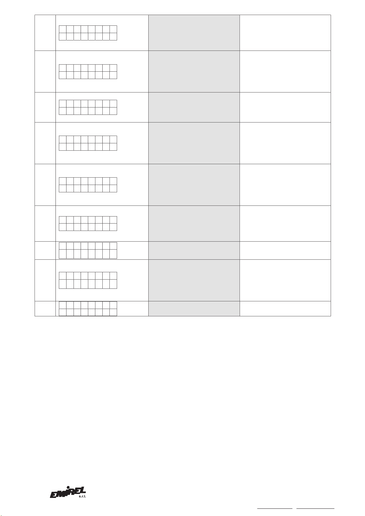
Per correnti maggiori di 35A si usa un TA xx/5 esterno
(adatto alla gamma di frequenze usate dall'Inverter). E'
necessario fare 3 passaggi del filo del secondario entro
l'A1-13, successivamente l'utente inserirà il corretto valore
RR nella schermata di SET "e" e nella schermata "a" si
sceglierà la gamma FS=15A.
TECHINICAL FEATURES AND REGULATIONS
The device provides four different operating modes:
1) SP=1 A single set-point S1 is active for the whole
range of the working frequency. (Fig. 2-A)
2) SP=3 The Three set-points divide the range of working
frequencies in three different zones, in each zone the
device can have a different set-point. For example, if the
load curve is represented as in Fig. 2-B C or D, the user
may choose this particular mode of operation.
3) SP=POS (rel. A) The user can set 16 set-points (Ia...
In) as a function for example of 17 different distances
between the crane trolley and his central body . The
distance is acquired via a 4-20mA signal to pins 21,20.
4) SP=POS (rel. B) The user can set 18 set-points
(Ia...Io) as a function for example of 18 different distances
between the crane trolley and his central body.
The distance is acquired via a 0-10Vdc signal to pins
21,20.
In all modes of operation the alarm set-points can be set
individually using the UP and DOWN keys or can be
stored with the procedure AUTO SET.
Tc (0-120 sec) [f5]
Initial timer (0-120 sec) adjustable by UP and DOWN
keys into the SET screen "f5".
It makes the device "blind" at the current starting, in order
to bypass the current spike at the motor start up.
T1 (0-120 sec) [f1]
Alarm delay time used in the following modes:
SP=1 in the whole range of frequencies
SP=3 into the frequency range 0 < F < (F1 +5Hz)
SP=POS in the whole range of frequencies
T2 (0-120 sec) [f2]
Alarm delay time used in the mode SP=3 into the
frequency range (F1 +5Hz) < F < (F2 +5Hz)
T3 (0-120 sec) [f3]
Alarm delay time used in the mode SP=3 into the
frequency range (F2 +5Hz) < F < (F3 +5Hz)
Tt (0-120 sec) [f4]
Alarm delay time for PTC sensors or Clicson
I0 [B]
On the front of the device is available the adjustment
trimmer I0 that allows the storage of the value of the
magnetizing current of the motor.
That current I0 can be subtracted from the measured
current value in order to obtain on the analog outputs the
value of current that actually produces the useful torque.
MODE OF OPERATION
The device has a DISPLAY (2x8 characters), using the
MODE button the user can surf through the different
screens.
Using the UP and DOWN keys the user can change the
values in some SET screens.
Using the AUTO key, the user can make the AUTO SET
of the S1 current value for mode of operation SP=1.
Using the AUTO key, the user can make the AUTO SET
of the I1, F1; I2, F2; I3, F3 current and frequency values
for mode of operation SP=3.
Using the AUTO key, the user can make the AUTO SET
of the Ia...In current values for mode of operation POS.
The device has 5 current ranges: 15-20-25-30-35 A
selectable in the SET screen "a".
For currents up to 35A the insertion is direct (the wire
must pass through the hole of the A1-13). For currents
higher than 35A an external CT xx/5 is required (suitable
for the range of frequencies used by Inverter). The
secondary wire of the external CT must pass three times
through the A1-13, then the user will insert the right value
of RR in the SET screen "e" and select the range FS =
15A in the SET "a" screen.
Viale Caduti per la Libertà, 4b - 40050 MONTE S. PIETRO - BOLOGNA (ITALY) –
Tel. 051/6761552 - Fax 051/6760492 - Internet: http://www.emirel.it - E-mail: info@emirelsrl.it / [email protected] 3
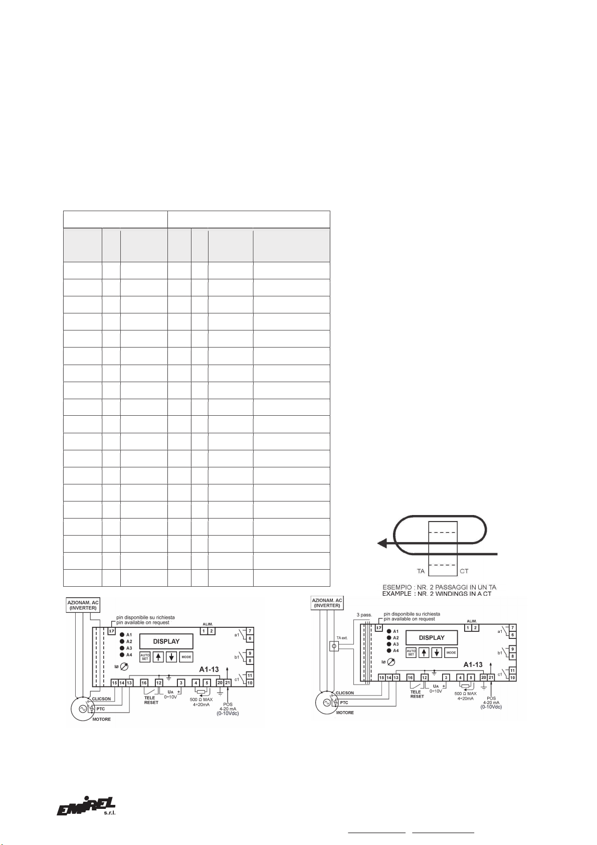
Legenda TAB. A
FS=fondo scala A1-13 (15-20-25-30-35) [a]
Ip=corrente del primario del TA esterno
Is=corrente del secondario del TA esterno
RR=Ip/Is : Es.: TA 50/5 : RR=50/5=10 [e]
IN: corrente di targa del motore (400Vac)
n=numero di passaggi del filo di corrente nel TA
esterno
N [d] : senza TA esterno: numero di passaggi del filo
di corrente nell’A1-13 con TA esterno: numero
di passaggi del filo collegato al secondario del
TA, nell’A1-13
NOTA 1:
La colonna denominata “uscita analogica” mostra il peso in
“A” che deve essere attribuito ad ogni “volt” dell’uscita
analogica a seconda del motore utilizzato.
Fig. 4
VISUALIZZAZIONE
LED A1, A2, A3 (rossi), A4 (blu).
Legend TAB. A
FS=current full scale of the A1-13 (15-20-25-30-35)[a]
Ip=primary current of the external CT
Is=secondary current of the external CT
RR=Ip/Is : Ex.: CT 50/5 RR=50/5=10 [e]
IN: rated current of the motor (400Vac)
n=number of wiring of the amperometric phase trough
the hole of the external CT
N [d] : without external CT: number of wirings of the
amperometric phase through the hole of the
A1-13 with external CT: number of wirings of
the cable connected to the secondary of the
external CT through the hole of the A1-13
REMARK 1:
The column called “analog output” shows the weight in “A”
that must be assigned to each “volt” of the analog output.
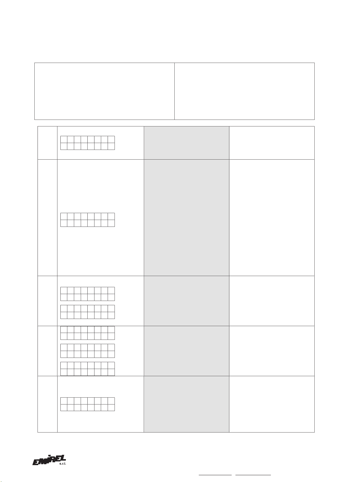
NOTA 2: per motori di piccola taglia In<6,6A sarà
necessario fare “N” passaggi nel foro dell’A1-13. Il
valore del parametro “N” da inserire si ricava da
N=15/In, (N varia da 1 a 5).
REMARK 2: for small size motors (In<6,6A) the
user must do “N” passages through the hole of the
A1-13. The value of N comes from N=15/In
(variable from 1 to 5).
Esempio / Example 1:
In=3,6A FS=15A N=15/3,6=4,2 ®N=4
Esempio / Example 2:
In=22A FS=25A N=1
Esempio / Example 3:
Utilizzo TA esterno
/ With external CT In=80A
TA=100/5 n=1 (passaggi nel primario del TA)
(passages through the hole of CT)
FS=15A N=3 RRTA=100/5=20
Esempio / Example 4:
Utilizzo TA esterno (2) /
With external CT (2)
In=80A TA=200/5 n=2 (passaggi nel primario del
TA): fare 2 passaggi nel TA e questo diventa un
100/5. (passages through the hole of CT): with 2
passages through the CT hole it becomes a 100/5
CT. FS=15A N=3 RRTA= 100/5=20
Fig.
5
VISUALIZATIONS
LEDS A1, A2, A3 (red), A4 (blue).
TAB. A
VD=400 Vac
A1
-
13
IN (A)
n
TA est.
Ext. CT
RR
N
FS(A)
Uscita analogica
Analog output
1V ®x,x A
2,6
-
-
1
5
15
1V ®0,3
3,6
-
-
1
4
15
1V
®
0,37
5 - - 1 3
15 1V ®0,5
6,6 - - 1 2
15 1V ®0,75
8,5 - - 1 1
15 1V ®1,5
11,3
-
-
1
1
15
1V ®1,5
15,2
-
-
1
1
15
1V ®1,5
21,7
-
-
1
1
20 or 25
1V ®2,0 or 2,5
29,3
-
-
1
1
30
1V ®3,0
36
-
-
1
1
35
1V
®
3,5
41 1 50/5 10 3
15 1V ®5,0
55 1 50/5 10 3
15 1V ®5,0
55 2 100/5 10 3
15 1V ®5,0
68
1
100/5
20
3
15
1V ®10,0
68
2
200/5
20
3
15
1V ®10,0
81
1
100/5
20
3
15
1V ®10,0
81
2
200/5
20
3
15
1V ®10,0
99
1
100/5
20
3
15
1V ®10,0
99
2
200/5
20
3
15
1V
®
10,0

Viale Caduti per la Libertà, 4b - 40050 MONTE S. PIETRO - BOLOGNA (ITALY) –
4Tel. 051/6761552 - Fax 051/6760492 - Internet: http://www.emirel.it - E-mail: [email protected] / [email protected]
LED A1
E' attivo nel funzionamento SP=1.
Lampeggia al supero della soglia S1 e dopo il tempo di
ritardo T1 passerà a luce piena e il relè A apre il suo
contatto. (Fig.6)
La chiusura momentanea di un contatto fra i pin 16-12 (tele-
reset) spegne il led A1 e resetta il relè A.
LED A2
E' attivo nel funzionamento SP=3.
Lampeggia al supero delle soglie I1, I2, I3.
Dopo il relativo tempo di ritardo passerà a luce piena e il
relè B apre il suo contatto (Fig.7).
Alle 3 soglie di allarme sono collegati 3 tempi di ritardo
impostabili dall'utente, T1 per I1, T2 per I2, T3 per I3.
La chiusura momentanea di un contatto fra i pin 16-12 (tele-
reset) spegne il led A2 e resetta il relè B.
LED A3
E' attivo nel funzionamento POS.
Lampeggia al supero di una delle "In" soglie.
Dopo il tempo di ritardo T1 passerà a luce piena e il relè C
apre il suo contatto.
Nella figura 8 è raffigurato l'intervento di una delle "n" soglie
impostabili.
La chiusura momentanea di un contatto fra i pin 16-12 (tele-
reset) spegne il led A3 e resetta il relè C.
LED A4 [i]
Il led A4 segnala l'intervento dei sensori termici, PTC o
CLICSON, presenti nel motore.
Lampeggia all'apertura di uno di questi sensori.
Dopo il tempo di ritardo Tt passerà a luce piena e il relè C
apre il suo contatto.
La scelta del controllo fra:
NN : Nessun sensore
PTC: sensore PTC ( 3 o 6 sensori)
CLI : sensore CLICSON
è stata fatta nella schermata "i" del Menu SET.
La chiusura momentanea di un contatto tra i pin 16-12
(Telereset) spegne il led A4 e resetta il relè C.
Il LED A4 è anche collegato alle operazioni di
memorizzazione tramite AUTO, quando si esegue la
memorizzazione di un parametro il led si accenderà
momentaneamente e contestualmente sul display
apparirà il messaggio "MEM".
TARATURA
Portarsi nella schermata [j] e scegliere il tipo di
funzionamento desiderato.
FUNZIONAMENTO SP=1 [j]
La soglia di allarme S1 è attiva ad ogni frequenza di lavoro
(fig.6).
L'utente ha due modi per impostare la soglia S1:
1) A motore fermo.
Entrare nel menù SET
Inserire la pwd
Portarsi nella schermata "l" impostare il valore di S1
desiderato.
2)
Posizionarsi nella schermata "
A
"
LED A1
A1 is active in the operating mode SP=1.
The led A1 flashes when the current I overcomes the set
point S1.
After the delay time T1 the led A1 will be lit and the relay A
opens its contact. (Fig. 6)
The temporary closing of a contact between pins 16-12
(remote reset) turn off the led A1 and resets the relay A.
LED A2
A2 is active in the operating mode SP=3.
The led A2 flashes when the current I overcomes the set
points I1 or I2 or I3.
After the correspondent time delay the led A2 will be lit
and the relay B opens his contact (Fig. 7).
The three alarm set points I1 , I2, I3 are connected to
three user-settable delay times, T1 for I1,T2 for I2 and T3
for I3.
The temporary closing of a contact between pins 16-12
(remote reset) turn off the led A2 and resets the relay B.
LED A3
A3 is active in the operating mode POS.
The led A3 flashes when the current I overcomes one of
the set points "In".
After the delay time T1 the led A3 will be lit and the relay C
opens its contact.
In Fig. 8 is shown the intervention of one of the "n"
settable set-points.
The temporary closing of a contact between pins 16-12
(remote reset) turn off the led A3 and resets the relay C.
LED A4 [i]
The led A4 indicates the intervention of thermal sensors,
PTC or CLICSON present inside the motor.
The led A4 flashes during Tt, after the delay time Tt the
led A4 will be lit and the relay C opens its contact.
The choice of control between:
NN = No sensors
PTC: PTC sensor (3 or 6 sensors)
CLI: CLICSON sensor
was made on the screen "i" of the SET menu
The temporary closing of a contact between pins 16-12
(remote reset) turn off the led A4 and resets the relay C.
The LED A4 is also connected to the storage
operations using AUTO key, when the user stores a
parameter, the LED will light momentarily and
simultaneously on the display the message "MEM" is
present.
SETTING
The user must go to the [j] screen and chooses the mode
of operation desired.
MODE SP=1 [j]
The set point S1 is active in the whole range of frequency
(fig.6)
The user has two ways to set the set point S1:
1) The motor is OFF.
Enter the SET menu
Enter the PASSWORD
Go to the
"l"
screen to set the desired value of
S1
.
Fig. 6 Fig. 7 Fig. 8

Viale Caduti per la Libertà, 4b - 40050 MONTE S. PIETRO - BOLOGNA (ITALY) –
Tel. 051/6761552 - Fax 051/6760492 - Internet: http://www.emirel.it - E-mail: info@emirelsrl.it / [email protected] 5
Premere il tasto AUTO.
Inserire la password.
Avviare il motore e portarlo al punto di funzionamento
desiderato.
Premere il tasto AUTO fino a quando non apparirà sullo
schermo la scritta MEM e il led blu non si accenderà.
Spegnere il motore ed eventualmente ritoccare la soglia S1
memorizzata con i tasti UP e DOWN.
FUNZIONAMENTO SP=3 [j]
Le soglie di allarme I1, I2, I3 sono attive in 3 intervalli distinti
di frequenza 0-F1, F1-F2, F2-F3.
Per individuare i 3 punti di lavoro (I1, F1), (I2, F2), (I3, F3)
seguire la seguente procedura:
1) Posizionarsi nella schermata [A]
Premere il tasto AUTO.
Inserire la password.
2) Avviare il motore e portare l'inverter nel punto di lavoro
desiderato (frequenza F1) con il carico opportuno (I1).
Premere il tasto AUTO fino a quando non apparirà sullo
schermo la scritta MEM e il led blu non si accenderà,
memorizzazione (I1, F1) eseguita.
3) Premere il tasto MODE.
Portare l'inverter nel nuovo punto di lavoro desiderato
(frequenza F2) con il carico opportuno (I2).
Premere il tasto AUTO fino a quando non apparirà sullo
schermo la scritta “MEM” e il led blu non si accenderà,
memorizzazione (I2, F2) eseguita.
4) Premere il tasto MODE.
Portare l'inverter nel nuovo punto di lavoro desiderato
(frequenza F3) con il carico opportuno (I3).
Premere il tasto AUTO fino a quando non apparirà sullo
schermo la scritta MEM e il led blu non si accenderà,
memorizzazione (I3, F3) eseguita.
A motore fermo, è possibile ripetere la procedura
precedente per ritoccare i valori di I1, I2, e I3 memorizzati
agendo coi tasti UP, DOWN e MODE al posto del tasto
AUTO.
NOTA 3: Per non avere indecisioni nel funzionamento reale
vengono sommati 5Hz ai valori di F1, F2 ed F3, in modo da
ottenere un intervallo di frequenze che contenga
sicuramente le frequenze di partenza.
FUNZIONAMENTO POS [j]
Un trasduttore esterno con uscita 4-20mA (per A1-13 A) o
0-10V (per A1-13 B) comunica al dispositivo il valore "Dn"
acquisito attivando quindi la corrispondente soglia di
allarme "In".
Per esempio un trasduttore di posizione comunica al
dispositivo la distanza tra carrello e corpo della gru.
Per memorizzare le "In" soglie seguire la seguente
procedura:
- Posizionarsi nella schermata "A"
Premere il tasto AUTO.
Inserire la pwd.
- Posizionare il carrello della gru nella posizione desiderata.
Sollevare il carico desiderato.
Premere il tasto AUTO fino a quando non apparirà sullo
schermo la scritta MEM e il led blu non si accenderà.
La memorizzazione di “Ia” è stata eseguita.
- Posizionare il carrello della gru nella posizione desiderata.
Sollevare il carico desiderato.
Premere il tasto AUTO fino a quando non apparirà sullo
schermo la scritta MEM e il led blu non si accenderà.
La memorizzazione di “Ib” è stata eseguita.
- Ripetere il punto precedente per tutte le soglie "In"
rimanenti.
A motore fermo, è possibile ripetere la procedura
precedente per ritoccare i valori di In memorizzati agendo
coi tasti UP, DOWN e MODE al posto del tasto AUTO. La
selezione delle varie soglie "In" avverrà con la pressione del
tasto MODE e non con lo spostamento del carrello della
2) Go to the "A" screen
Press AUTO key.
Enter the PASSWORD
Start the motor and bring it to the desired operating point.
Press AUTO key until "MEM" message appears on the
screen and the blue LED will not turn on.
Turn off the engine and if necessary, adjust the set point
S1 stored with the UP and DOWN keys.
MODE SP=3 [j]
The set points I1, I2, I3 are active in three different ranges
of frequency 0-F1, F1-F2, F2-F3.
In order to find the three operating point (I1, f1), (I2, F2),
(I3, F3) follow the following steps:
1) Move to the [A] screen
Press AUTO key.
Enter the Password.
2) Turn on the inverter and bring it to the desired operating
point (frequency F1) with the appropriate load (I1).
Press AUTO key until "MEM" message appears on the
screen and the blue led will not turn on, the storage of (I1,
F1) is done.
3) Press MODE key.
Bring the inverter to the new desired operating point
(frequency F2) with his new appropriate load (I2).
Press AUTO key until "MEM" message appears on the
screen and the blue LED will not turn on, the storage of
(I2, F2) is done.
4) Press MODE key.
Bring the inverter to the new desired operating point
(frequency F3) with his new appropriate load (I3).
Press AUTO key until "MEM" message appears on the
screen and the blue led will not turn on, the storage of (I3,
F3) is done.
With the motor turned off, user can repeat the above
procedure to adjust the values of I1, I2, and I3 stored
using the UP, DOWN and MODE keys instead of the
AUTO key.
REMARK 3: In order to avoid indecisions in actual
operation 5Hz are added to the values of F1, F2 and F3, in
order to obtain a frequency working range that contains
definitely the starting frequencies F1, F2 and F3.
MOD POS [j]
An external transducer with 4-20mA output (for A1-13 rel.
A) or 0-10Vdc (for A1-13 rel. B) indicates to the device
the current value "Dn" order to activate the corresponding
alarm set point "In". For example a positional transducer
could communicate to the device the distance between
trolley and crane body.
In order to store the "In" set points follow the following
procedure:
- Move to "A" screen
Press AUTO key.
Enter the PASSWORD
- Move the crane trolley to the desired position.
Lift the desired load.
Press AUTO key until "MEM" message appears on the
screen and the blue LED will not turn on, the storage of
"Ia" is done.
- Move the crane trolley to the new desired position.
Lift the desired load.
Press AUTO key until "MEM" message appears on the
screen and the blue LED will not turn on, the storage of
"Ib" is done.
- Repeat the previous step for all the remaining "In" set
points.
With the motor turned off, user can repeat the above
procedure to adjust the values of In stored using the UP,
DOWN and MODE keys instead of the AUTO key. The
selection of the different set points "
In
" will take place by

Viale Caduti per la Libertà, 4b - 40050 MONTE S. PIETRO - BOLOGNA (ITALY) –
6Tel. 051/6761552 - Fax 051/6760492 - Internet: http://www.emirel.it - E-mail: [email protected] / [email protected]
gru.
RIPRISTINO [b]: A seconda dell'impostazione del
parametro "Alm" nella schermata di setup "b", il dispositivo
risulterà a ripristino automatico o no, in questo secondo
caso per il reset degli allarmi si dovrà utilizzare il contatto
esterno di TELERESET (pin16-12) o premere
contemporaneamente i pulsanti UP e DOWN (bisogna
essere nella schermata "A").
SICUREZZA INTRINSECA
I relé interni sono normalmente ON e vanno OFF in caso di
allarme.
TELERESET: pin 16-12 la chiusura momentanea di un
contatto NA (libero da tensione) resetta ogni allarme
presente (la stessa funzione si ottiene premendo
contemporaneamente UP e DOWN).
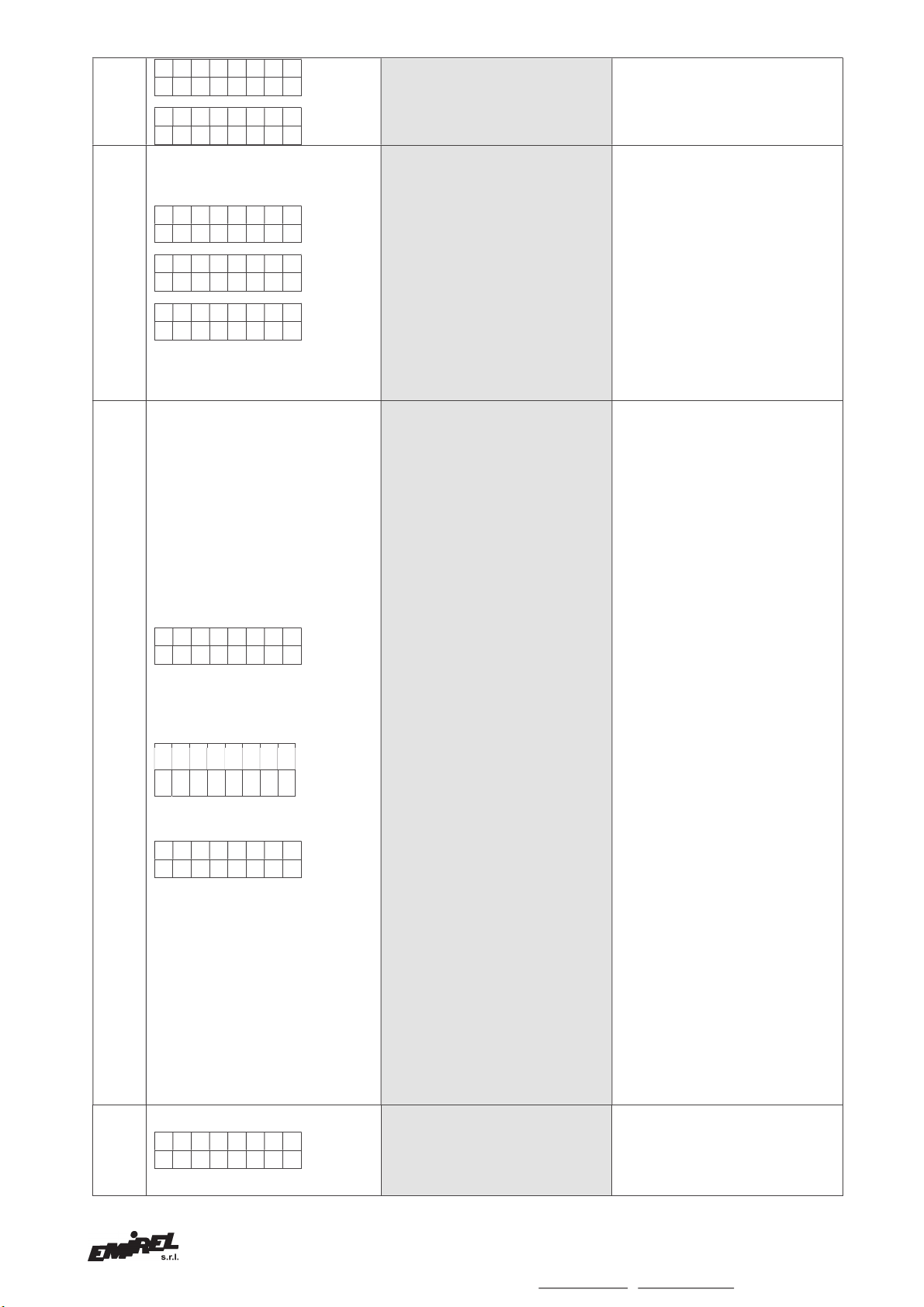
COLLEGAMENTI ELETTRICI
A vite per filo fino 1,5mm2(14 AWG)
(Collegamento a un quadro elettrico con differenziale e
sezionatore).
La lunghezza di ogni collegamento deve essere < 30m.
INSTALLAZIONE:
In caso di inserzione diretta vedi fig.4.
In caso di uso di TA esterno vedi fig.5.
INGRESSO POS 4-20 mA (Versione A):
pin 21 (+) ,20 (impedenza di ingresso 100ohm)
INGRESSO POS 0-10 Vdc (Versione B):
pin 21 (+) ,20 (impedenza di ingresso 100Kohm)
INGRESSO PTC: pin 13-14
INGRESSO CLICSON: pin 13-15
INGRESSO DIGITALE: pin 17 (pin non utilizzato,
programmabile via software su richiesta del cliente).
USCITE:
relè A pin 6-7 3A 230 Vac ( carico res.)
SICUREZZA INTRINSECA
relè B pin 8-9 3A 230 Vac ( carico res.)
SICUREZZA INTRINSECA
relè C pin 10-11 3A 230 Vac ( carico res.)
SICUREZZA INTRINSECA
USCITE ANALOGICHE [h]:
1) TENSIONE: 0-10 V pin 3(+) - 12 R carico :
maggiore 10 kOhm
2) CORRENTE: 4- 20 mA pin 5(+) - 4 R carico :
500 Ohm max.
Le Uscite analogiche sono disponibili per una
visualizzazione esterna o per una registrazione dati la I
misurata o la I-I0 (questa scelta è fatta alla schermata "h" ).
In caso di scelta di I-I0 si ottiene la visualizzazione esterna
della corrente che effettivamente produce la coppia utile.
ALIMENTAZIONE:
pin 1-2 6VA 50-60 Hz ±10%, 230 Vac, oppure 24Vac
DIMENSIONI : 100x 75 x110 mm per guida DIN
TEMPERATURA FUNZ. : 0-60°C
MISURE DI SICUREZZA
Il dispositivo DEVE essere installato esclusivamente all’interno di un
quadro elettrico chiuso mediante chiave o dispositivo analogo.
L’accesso al suddetto quadro e di conseguenza al dispositivo DEVE
essere effettuato esclusivamente a quadro disalimentato e SOLO
dal personale di manutenzione o di installazione opportunatamente
formato ed addestrato alla operazione prevista.
Per la pulizia usare un panno imbevuto di detergenti privi di:
Alcool denaturato, Benzene, Alcool isopropilico.
COMPATIBILITA' ELETTRO
MAGNETICA
Electromagnetic compatibility
CEI
-
EN 61326
-
1
“BASSA TENSIONE” - LVD
LVD – “LOW VOLTAGE”
CEI-EN 61010-1
pressing the MODE key and not with the movement of the
crane trolley.
RESET [b]: Depending on the setting of the parameter
"Alm" in the SET screen "b", the device will have the
automatic reset or not, in the latter case to reset the
alarms the user could use the external TELERESET (pin
16-12) or press simultaneously the UP and DOWN keys
(the user must be in screen "A").
POSITIVE SAFETY
The internal relays are normally ON and they go OFF
when the set point is overcome.
TELERESET: the temporary closing of a contact (voltage
free) between pins 16-12 resets every alarm (the same
function as pressing UP and DOWN keys at the same time
in the screen "A").
CONNECTIONS
Screw connections for cables up to 1,5mm2(14 AWG).
(Wiring to an electrical board with a differential relay and a
sectionalizing switch).
The length of every wiring must be less than 30m.
INSTALLATION :
In case of direct insertion see fig.4.
In case of use of an external CT see fig.5.
INPUT POS 4-20 mA (rel. A):
pin 21 (+) ,20 (Rin 100ohm)
INPUT POS 0-10 Vdc (rel. B):
pin 21 (+) ,20 (Rin 100Kohm)
INPUT PTC: pin 13-14
INPUT CLICSON: pin 13-15
DIGITAL INPUT: pin 17 (not used, settable via software
on customer's request).
OUTPUTS :
relay A pin 6-7 3A 230 Vac (resistive load)
POSITIVE SAFETY
relay B pin 8-9 3A 230 Vac (resistive load)
POSITIVE SAFETY
relay C pin 10-11 3A 230 Vac (resistive load)
POSITIVE SAFETY
ANALOG OUTPUTS [h]:
1) VOLTAGE: 0-10 V pin 3(+) - 12 R load
greater than 10 kOhm
2) CURRENT: 4-20 mA pin 5(+) - 4 R load :
500 Ohm max.
On the two analog outputs are available, for an external
display or for a data recording, the measured value of "I"
or "I-I0" (this choice is made in the SET screen "h").
In case of choice of "I-I0" is obtained the representation of
the current that actually produces the useful torque.
SUPPLY : pin 1-2 6VA 50-60 Hz ±10%, 230 Vac, or
24Vac
DIMENSIONS : 100x75 x110mm DIN rail
OPERATING TEMP. : 0-60°C
SECURITY MEASURES
The device MUST be installed only inside a electrical panel
closed by a key or similar device.
Access to this electrical panel and consequently at the device
MUST be done exclusively with panel switched off and ONLY by
maintenance or installation personnel suitably formed and trained
for the planned operation.
For cleaning use a cloth soaked with detergents without:
Denatured Alcohol, Benzene, Isopropyl alcohol.
Viale Caduti per la Libertà, 4b - 40050 MONTE S. PIETRO - BOLOGNA (ITALY) –
Tel. 051/6761552 - Fax 051/6760492 - Internet: http://www.emirel.it - E-mail: info@emirelsrl.it / [email protected] 7
A1-13 LIMITATORE DI COPPIA
PER MOTORE TRIFASE ALIMENTATO (anche) DA INVERTER
IMPOSTAZIONE PARAMETRI DI FUNZIONAMENTO
Mediante tasti UP e DOWN presenti sul frontale del
dispositivo.
Mediante tasti UP e DOWN presenti sul frontale del
dispositivo e automaticamente se in modalità
“auto-apprendimento”.
Di seguito è riportata la successione delle
schermate di visualizzazione e impostazione del
dispositivo e il loro funzionamento:
Using UP and DOWN keys on the front panel of the
device.
Using UP and DOWN keys on the front panel of the
device and automatically in case of AUTOSET mode
of operation
The following is a description of the operation of
each device window.
1 I
=
x
x
. x
A
F
=
x
x
H
z
In questa
schermata sono visualizz
ate
la corrente istantanea I del motore e
la sua frequenza F
Le frequenze operative del dispositivo
vanno da una minima di 3 Hz ad una
massima di 150 Hz.
This screen displays the current I
absorbed by the electric motor and its
operating frequency F.
The operating frequency of the device
ranging from a minimum of 3 Hz to a
maximum of 150 Hz.
2
P
O
S
=
x
x
B
I
0
=
x
. x
A
POS è la posizione 0-16 (17 posizioni
in tutto) del carrello della gru rispetto
al corpo della stessa. Nel
funzionamento “POS” ad ogni
posizione corrisponde una soglia di
intervento diversa. Ognuna di queste
soglie può essere inserita (modificata)
con i tasti UP/DOWN o memorizzata
attraverso l'AUTOSET.
La corrente I0 (impostabile
manualmente con il trimmer frontale)
può rappresentare la corrente a vuoto
del motore stesso. Per una corretta
impostazione si può far funzionare il
motore a vuoto e contestualmente
agire sul trimmer frontale fino a
quando sul display del dispositivo I e
I0 non avranno lo stesso valore.
POS is the position 0-16 (totally 17
positions) of the crane trolley respect
to her body .
In the "POS" operating mode at every
position corresponds a different SET
POINT "In" for intervention.
Each of these SET POINTS can be set
(and modified) with the UP / DOWN
keys or stored with the AUTOSET
procedure.
The I0 current (manually set with the
front trimmer I0) can represent the
current of the unloaded motor. For a
correct setup you can run the motor
without any load and simultaneously
act on the front trimmer I0 until I0=I.
3
U
a
C
U
a
- >
I
U
a
C
U
a
- >
I
- I
0
In questa schermata è visualizzata la
scelta operata circa l’uscita analogica
(0-10V 4-20mA). E’ possibile avere in
uscita solo l’indicazione dell’effettiva
corrente istantanea I del motore
oppure il valore di I-I0 dove I0
rappresenta la corrente a vuoto del
motore, in pratica la corrente “persa”
del motore stesso.
In this screen is shown the choice
made about the analog output (0-10V
4-20mA).
It is possible to have output only the
indication of the actual instantaneous
current I of the motor or the I-I0 value
where I0 represents the unloaded
current of the motor.
4
C
T
=
N
N
D
C
T
=
P
T
C
D
C
T
=
C
L
I
D
In questa schermata è indicata quale
protezione termica è collegata al
dispositivo. Sono possibili 3 scelte:
1. nessuna protezione “NN“
2. PTC “PTC” (pin 13-14)
3. Clicson “CLI” (pin (13-15)
On this screen is shown what thermal
protection is connected to the device.
There are 3 different choices:
4. no protection “NN“
5. PTC “PTC” (pin 13-14)
6. Clicson “CLI” (pin 13-15)
5 S
E
T
E
p
w
d
=
x
x
x
In questa schermata è possibile
inserire la password per poter
accedere al menù di configurazione del
dispositivo. La pwd può variare tra 0 e
999 . Se si inserisce la pwd errata con
la pressione del tasto MODE si tornerà
alla schermata A
Di default PWD=01
In this screen the user can ent
er th
e
password to access the SET menu of
the device.
The password can be modified
between 0 and 999.
If a wrong password has been entered
by pressing the MODE key the device
returns to the screen "A" .
The default value is PWD=01

Viale Caduti per la Libertà, 4b - 40050 MONTE S. PIETRO - BOLOGNA (ITALY) –
8Tel. 051/6761552 - Fax 051/6760492 - Internet: http://www.emirel.it - E-mail: [email protected] / [email protected]
6
S
E
T
a
F
S
=
1
5
A
S
E
T
a
F
S
=
2
0
A
S
E
T
a
F
S
=
2
5
A
S
E
T
a
F
S
=
3
0
A
S
E
T
a
F
S
=
3
5
A
In questa schermata viene impostato il
valore di fondo scala di funzionamento
del dispositivo.
Le soglie di allarme sono dipendenti
dal valore di fondo scala impostato.
E’ necessario scegliere il fondo scala
più appropriato in funzione della taglia
del motore.
In caso di utilizzo di un TA esterno
viene automaticamente selezionato
FS=15. Per una maggiore precisione è
opportuno fare 3 passaggi del filo del
secondario del TA esterno all'interno
del TA dell'A1-13 (ovviamente
impostando poi N=3 nell'apposita
schermata)
In this screen the user can set the FS
value of the full scale of the device.
The alarm set-points are dependent on
the FS value set.
It is necessary to choose the most
appropriate FS value depending of the
size of the electric motor.
In case of using an external CT is
automatically selected FS = 15 and
the user must do three pass through
the device's hole.
After that, N=3 must be selected in
the “d” SET screen.
7
S
E
T
b
A
l m
=
m
a
n
a
u
t
Questa schermata consente di
impostare il tipo di ripristino del
dispositivo dopo un allarme.
Aut: appena cessa la condizione di
allarme il dispositivo si riabiliterà
Man: per resettare il dispositivo sarà
necessario agire sul reset esterno o su
quello frontale.
In this screen the user can set the
type of device reset.
Aut: automatic reset at the end of the
alarm condition
Man: manual reset, using the external
contact or the reset key on the front
panel of the device
9 S
E
T
d
N
=
x
N è il numero di passaggi nel TA del
cavo della corrente che si vuole
misurare. N è variabile da 1 a 5
Esempio: Se uso un motore da 7A
posso selezionare FS=15A e fare N=2
passaggi nel TA oppure posso
selezionare FS=35 e fare 5 passaggi
nel TA
N is the number of passes through the
hole of the device's CT of the current
cable that we want to measure. N is
variable from 1 to 5.
Example: In case of motor with
IN=7A select
FS = 15A and N = 2.
Otherwise, the user can select FS =
35A and N = 5.
10 S
E
T
e
R
R
=
x
x
x
RR è
il rapporto spire del TA
e
sterno
che si deve usare quando la corrente
del motore è maggiore di 35A
1 < RR < 100
Esempio: in caso di TA esterno 100/5,
RR=100/5=20
RR is the turns ratio of the external CT
that should be used when the motor
current is greater than 35A.
1 < RR < 100
Example: In case of 100/5 CT,
RR=100/5=20
11 S
E
T
f 1
T
1
=
x
x
x
s
Tempo di ritardo di allarme valido per
il funzionamento :
·SP=1 in tutto il range di
frequenze
·SP=3 nel range 0 < f <
(F1+5)
·SP=POS in tutto il range
di frequenze
T1 varia da 0 a 120 sec
Time delay
of the alarm set point ,
active in the following operations:
·SP=1 in the whole range of
frequencies
·SP=3 in the range 0 < f <
(F1+5Hz)
·SP=POS in the whole range
of frequencies
0 < T1 < 120 sec
12 S
E
T
f 2
T
2
=
x
x
x
s
Tempo
di ritardo di allarme valido per
il funzionamento SP=3 nel range di
frequenza
(F1+5) < f < (F2+5)
T2 varia da 0 a 120 sec
Time delay of the alarm set
point,
active in case of SP=3 working mode
in the following frequency range
(F1+5Hz) < f < (F2+5Hz)
0 < T2 < 120 sec
13 S
E
T
f 3
T
3
=
x
x
x
s
Tempo di ritardo di allarme valido per
il funzionamento SP=3 per frequenze
f > (F2+5)
T3 varia da 0 a 120 sec
Time delay of the alarm set point,
active in case of SP=3 working mode
in the following frequency range
(F2+5Hz) < f < (F3+5Hz)
0 < T3 < 120 sec
14 S
E
T
f 4
T
t =
x
x
x
s
Tempo di ritardo di allarme per PTC e
Clicson
Tt varia da 0 a 120 sec
Time delay of the alarm of the PTC or
Clicson
0 < Tt < 120 sec
15 S
E
T
f 5
T
c
=
x
x
x
s
Tempo
di cecità allo spunto del
motore.
Tc varia da 0 a 120 sec
Time delay at the start of the motor in
order to avoid the initial current spike.
0 < Tc < 120 sec
16 S
E
T
g
I
N
=
x
x
A
Corrente di targa del motore.
1 < IN < 500A
Per motori più grandi di FS=35A è
necessario usare un TA esterno
Rated motor current IN
(see the motor plate)
1 < IN < 500A
In case of electric motor with IN >35A
an external CT is needed.
Viale Caduti per la Libertà, 4b - 40050 MONTE S. PIETRO - BOLOGNA (ITALY) –
Tel. 051/6761552 - Fax 051/6760492 - Internet: http://www.emirel.it - E-mail: info@emirelsrl.it / [email protected] 9
17
S
E
T
h
U
a
-
>
I
S
E
T
h
U
a
-
>
I
-
I
0
Schermata di scelta del tipo di uscite
analogica desiderata.
Agendo sui tasti UP e DOWN è
possibile scegliere se avere a
disposizione in uscita I o (I-I0)
In this screen the user could choose
which measure is shown in the analog
output.
Using the UP and DOWN keys it is
possible to select I or I-I0.
18
S
E
T
i
C
T
=
N
N
S
E
T
i
C
T
=
P
T
C
S
E
T
i
C
T
=
C
L
I
In questa schermata è possibile
scegliere quale protezione termica
collegare al dispositivo. Sono possibili
3 scelte:
1. nessuna protezione
“NN“
2. PTC “PTC” (pin 13-
14)
3. Clicson “CLI” (pin 13-
15)
L’eventuale allarme dovuto a queste
sonde è segnalato dal LED 4 ed è
sempre a ripristino manuale
Il relè associato a questo allarme è RC
In this screen t
he user can choose
which thermal protection connects to
the device. There are 3 possible
choices:
4. no protection “NN“
5. PTC “PTC” (pin 13-
14)
6. Clicson “CLI” (pin 13-
15)
The thermal alarm condition is
indicated by the LED A4 and it is
manually reset only.
The connected relay to this alarm is
the C relay.
19
S
E
T
j
S
P
=
1
S E T j
S P
=
3
P
O
S
=
x
x
j
I
x
=
x
x
. x
A
In questa schermata si sceglie che tipo
di funzionamento si vuole utilizzare.
1. SP=1: si avrà una soglia di
allarme S1 valida per tutto il
range di frequenza di
funzionamento del motore.
E’ il controllo meno
sofisticato. Premendo il tasto
MODE si andrà alla fine del
menù di configurazione. A
questo funzionamento è
associato il relè di allarme
RA e il LED A1.
2. SP=3: si dovranno
memorizzare tre punti di
funzionamento (F1,I1) ,
(F2,I2) e (F3,I3) durante
una prova con un peso
campione. Fatto questo il
dispositivo utilizzerà I1 come
soglia di allarme per
l’intervallo di frequenza 0-
F1+5Hz, utilizzerà I2 per
l’intervallo (F1+5Hz) –
(F2+5Hz) e utilizzerà I3 per
frequenze di funzionamento
superiori a F2+5Hz. A
questo funzionamento è
associato il relè di allarme
RB e il LED A2.
3. SP=POS: si dovranno
memorizzare o
manualmente con i tasti UP
e DOWN oppure tramite
AUTOSET fino a 17 soglie di
intervento diverse, una per
ogni diversa posizione che il
carrello della gru può
assumere. A questo
funzionamento è associato il
relè di allarme RC e il LED
A3.
In this screen, the user can choose
what type of operation he wants to
use.
4. 1. SP = 1: there is only one
setpoint (S1) for the entire
frequency range of
operation of the system. It
is the less sophisticated
control.
Pressing the MODE key you
will go to the end of the
configuration menu.
At this function is associated
the RA alarm relay and the
LED A1.
5. SP=3: 2. The user must
store three operating points
(F1, I1), (F2, I2) and (F3,
I3) using a TEST weight. 2.
Then the device will use I1
as set point for the
frequency range 0-(F1+5)
Hz, will use for the I2 set
point between (F1+5Hz)
and (F2+5Hz) and will use
I3 between (F2+5Hz) and
(F3+5Hz).
At this function is associated
the RB alarm relay and the
LED A2.
6. SP=POS: The user can
storage all the 17 (rel.A) or
18 (rel.B) different
setpoints, one for every
different position of the
crane trolley, manually using
the UP/DOWN and MODE
keys or automatically
following the AUTOSET
procedure. At this function is
associated the RC alarm
relay and the LED A3.
20a S
P
1
S
E
T
k
p
r
. M
O
D
E
È la schermata che appare prima di
cominciare la procedura di
memorizzazione della soglia di allarme
S1 in modalità SP=1. Premendo il
tasto MODE ci si porterà alla
schermata successiva.
This is the screen that appears before
you start the procedure for storing the
S1 alarm setpoint in the SP=1
operating mode.
Pressing the MODE key the system
moves to the next screen.
Viale Caduti per la Libertà, 4b - 40050 MONTE S. PIETRO - BOLOGNA (ITALY) –
10 Tel. 051/6761552 - Fax 051/6760492 - Internet: http://www.emirel.it - E-mail: info@emirelsrl.it / [email protected]
21a S
E
T
l
S
1
=
x
x
. x
A
S1 è il valore di soglia di
allarme di
MAX corrente che viene utilizzato in
caso di funzionamento manuale
(parametro SP = 1).
Quando I > S1 il led A1 si accenderà e
dopo il tempo T1 il relè RA andrà off.
S1 is the value of the MAX set point of
current that is used in the case of
manual operation (mode SP = 1).
When I>S1 the A1 LED will turn on
and after the delay time T1 the relay
RA will go off.
20b S
P
3
S
E
T
k
p
r . M
O
D
E
È la schermata che appare prima di
cominciare la procedura di
memorizzazione dei 3 punti di
funzionamento. Premendo il tasto
MODE ci si porterà alla schermata
successiva.
This is the screen that appears before
you start the procedure for storing the
three operating point (I1,F1), (I2,F2)
and (I3,F3) in the SP=3 operating
mode.
Pressing the MODE key the system
moves to the next screen.
20c-
37c
(38c)
P
O
S
=
x
x
k
I
x
=
x
x
. x
A
Queste sono le schermate (17 nella
vers. A, 18 nella vers. B) in cui si
possono consultare e modificare (se ci
si è arrivati tramite AUTO) le varie
soglie di intervento Ia...In
These are the screens (17 in the rel.A,
18 in the rel.B) where you can view
and modify (if the user is using the
AUTO SET procedure) the different set
points Ia ... In.
21b I
1
=
x
x
. x
A
f 1
=
x
x
H
z
Premendo il tasto AUTO si
memorizzerà l’istantaneo valore di
corrente e frequenza del motore.
Premendo il tasto MODE ci si sposterà
nella schermata successiva per poter
memorizzare il secondo punto di
funzionamento.
Pressing the AUTO key the system will
store the instantaneous value of
current I and frequency F, this is the
first operating point (I1,F1).
Press the MODE key to move to the
next screen in order to be able to
store the second operating point.
22b I
2
=
x
x
. x
A
f 2
=
x
x
H
z
Premendo il tasto AUTO si
memorizzerà l’istantaneo valore di
corrente e frequenza del motore.
Premendo il tasto MODE ci si sposterà
nella schermata successiva per poter
memorizzare il terzo punto di
funzionamento.
P
ressing the AUTO key the system will
store the instantaneous value of
current I and frequency F, this is the
second operating point (I2,F2).
Press the MODE key to move to the
next screen in order to be able to
store the second operating point.
23b I
3
=
x
x
. x
A
f 3
=
x
x
H
z
Premendo il tasto AUTO si
memorizzerà l’istantaneo valore di
corrente e frequenza del motore.
Premendo il tasto MODE ci si porterà
alla fine del menù di configurazione.
Pressing the AUTO key the system will
store the instantaneous value of
current I and frequency F, this is the
third operating point (I3,F3).
Press the MODE key to move to the
end of the SET menu.
38
S
E
T
p
p
w
d
=
x
x
x
Pagina di inserimento password,
variabile tra 0 e 999
This is the screen where the
user can
set the password system, variable
between 0 and 999
39
I
=
x
x
. x
A
q
s
t =
x
. x
x
Impostazione del valore di
aggiustamento “st” della lettura della
corrente I per poter tenere conto delle
imprecisioni del TA alle alte frequenze.
Il parametro “st” consente una
variazione del ± 20%
The "st" value is the fine-adjustment
of the current value I in order to
consider the inaccuracies of the CT at
high frequencies. The parameter "st"
allows a ±20% variation of I.
40 S
E
T
r
E
n
d
Fine del menù di configurazione. End of the SET menu.
Table of contents
Popular Safety Equipment manuals by other brands

Boreal
Boreal CLIMBING quick start guide

Pizzato Elettrica
Pizzato Elettrica CS AR-91 Series operating instructions

3M
3M DBI Sala EXOFIT User instructions

Aqua Lung
Aqua Lung 769161 user manual

Innotech
Innotech TAURUS-GLEIT-HO-50 quick start guide

Guardian
Guardian EyeSafe G1100 Installation, operation and maintenance

MSA
MSA SURETYMAN SRS15 Application, Operation, Maintenance & Inspection Instructions Manual

ABB
ABB JSM D23C installation guide

Urrea
Urrea USLV2 User manual and warranty

Capital Safety
Capital Safety DBI SALA EXOFIT NEX Rollgliss Explorer... manual

PepperBall
PepperBall BLAST instruction manual

MSA
MSA V-GARD 900 Series operating manual


