EMKO EZM-4450 User manual

EZM-XX50 Programmable Timers & Counters
ENGLISH
Programmable Timers & Counters
EZM-4450,EZM-4950,EZM-7750,EZM-9950
-
-
-Reset,PauseandChA-ChBCountingInputs
-NPN/PNP inputtypeselection
-ConfigurableCounter/TotalizerCounter,BatchCounter,Timer,
Chronometer,FrequencymeterandTachometer Functions
-ProgrammableTimeBasesforTimerandChronometer(Second,
Minute,Hour)
-
-OutputModuleSystem
-INC,DEC,INC/INC,INC/DEC,UP/DOWN,x1/x2/x4
-
-DifferentAlarmAlternativesinFrequencymeterandCycle
MeasuringFunctions
-Absolute or Offset Operation in Counter Function
-RS-232(standard)orRS-485(optional)SerialCommunicationwith
ModbusASCII or RTU Protocol
6 digits Process (PV) and 6 digits Set (SV) Value Display
Operationwith2SetValues
OperationwithAutomatic and Manual Reset
Counting
withPhaseShiftingPropertyinCounterFunction
MultiplicationCoefficientandDecimalPointPosition
EZM-4450,EZM-4950,EZM-7750,EZM-9950 Universal Input
Programmable Timer & Counter with Output Module System

SPECIFICATIONS
Phase Shifting
:
INPUT :
Output Modules : There are two module sockets for plugging the output modules.
- Relay Output Module
- SSR Output Module (Max. 26mA, 22V )
- Digital (Transistor) Output Module (Max.40mA@18V )
Counting Inputs (Ch-A,Ch-B): Switch, Proximity,Capacitive sensor or encoder can be
connected.
Reset Input: Switch, Proximity or Capacitive sensor can be connected.
Pause Input: Switch, Proximity or Capacitive sensor can be connected.
Input Type Selection: It can be selected NPN/PNP with DIP Switch that is located on
the device.
Reset Function: Automatic or Manual.
Count Input Types:
INC,DEC,INC/INC,INC/DEC,UP/DOWN ,x1 / x2 / x4: ( for encoder )
counting
OUTPUT
Z
Z
DISPLAY
Actual Count Value Display
ValueDisplay
:
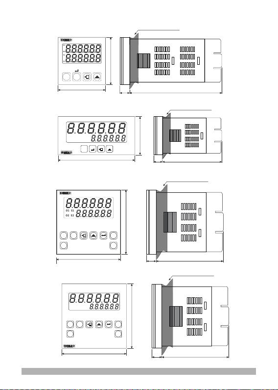
EZM-4450 :8mmRed6digitLEDDisplay
EZM-4950 :13.2mmRed6digitLEDDisplay
EZM-7750 :10.8mmRed6digitLEDDisplay
EZM-9950 :13.2mmRed6digitLEDDisplay
Set :
EZM-4450 :8mmGreen6digitLEDDisplay
EZM-4950 :8mmGreen6digitLEDDisplay
EZM-7750 :8mmGreen6digitLEDDisplay
EZM-9950 :8mmGreen6digitLEDDisplay
LEDs:S1(Set1value),S2(Set2value),O1/2(OutputStatus)LEDs.
SUPPLY VOLTAGE
Supply Voltage :
Must be determined in order.)
100-240 V V50/60 Hz (-15%;+10%) -6VA
24V V50/60 Hz (-15% ; +10%) -6VA
24V (-15% ; +10%) -6W
(Z
ENVIRONMENTAL RATINGS and PHYSICAL SPECIFICATIONS Operating
Temperature
Humidity none condensing
Protection Class
Weight
:0...50°C
: 0-90%RH ( )
:IP65 at Front, IP20 at rear.
Mounting: Type-1 Enclosure Mounting
:
EZM-4450 :210gr. ; EZM-4950 :210gr.
EZM-7750 : 250 gr. ; EZM-9950 : 340 gr.
Installation: Fixed installation Category II
Over Voltage Category: II
Pollution Degree: II, office or workplace, none conductive pollution
2

DIP SWITCH Adjustment
Electrical Wirings
Function Selection
Counter / Totalizer Counter
Batch Counter
Timer
Frequencymeter / Tachometer
Chronometer
Input Type Selection
NPN
PNP
Sensor
Supply
Communication
Module
RS-232(Standard)/
RS-485(Optional)
Supply
Switch
Output
Module-1
Relay, SSR or
Digital
(Transistor)
Output
Module-2
Relay, SSR or
Digital
(Transistor)
Max.50mA
Fuse
Note-3
(-) (+)
Note-1
a
External
Fuse
Note-2
Panel Cut-Out:
EZM-4450 : (46 x 46mm)
EZM-4950 : (92 x 46mm)
EZM-7750 : (69 x 69mm)
EZM-9950 : (92 x 92mm)
Dimensions:
EZM-4450 : (48 x 48mm,Depth:116 mm)
EZM-4950 : (96 x 48mm,Depth:86.5 mm)
EZM-7750 : (72 x72mm, Depth:87.5 mm)
EZM-9950 : (96 x 96mm,Depth:87.5 mm)
3

Sensor
Supply
Communication
Module
RS-232(Standard)/
RS-485(Optional)
Supply
Switch
Output
Module-1
Relay, SSR or
Digital
(Transistor)
Output
Module-2
Relay, SSR or
Digital
(Transistor)
Max.50mA
External
Fuse
Note-2
Fuse
Note-1
a
Note-3
(-) (+)
Sensor
Supply
Sensor
Supply
Communication
Module
RS-232(Standard)/
RS-485(Optional)
Communication
Module
RS-232(Standard)/
RS-485(Optional)
Supply
Switch
Supply
Switch
Output
Module-1
Relay, SSR or
Digital
(Transistor)
Output
Module-2
Relay, SSR or
Digital
(Transistor)
Output
Module-1
Relay, SSR or
Digital
(Transistor)
Output
Module-2
Relay, SSR or
Digital
(Transistor)
Max.50mA
Max.50mA
Note-1:Thereisaninternalfusibleflameproofresistor.
1AVTforpowersupply 240VVor24VV
1AZTforpowersupply24VZ
Note-3:“L”is(+),”N” is(-)for24VZ supplyvoltage
Note-2:Externalfuseisrecommended.
100...
External
Fuse
Note-2
External
Fuse
Note-2
Fuse
Note-1
a
Fuse
Note-1
a
Note-3
(-) (+)
Note-3
(-) (+)
4

DIMENSIONS
O1
O2
S1
S2
EZM-4450
TOTAL
PRESET
SET1 SET2
Timer & Counter
S1
S2
O1
O2
Timer & Counter
SET1 SET2 TOTAL
PRESET
O1 S1
O2 S2
Timer & Counter
EZM-7750
SET1 SET2
RESET PTOTAL
Maximum 5 mm / 0.2 inch
48 mm / 1.89 inch
48 mm / 1.89 inch
Maximum 15 mm / 0.59 inch
11.5±1mm/0.45 inch 104.5mm / 4.11 inch
48 mm / 1.89 inch
96 mm / 3.78 inch 10.5±1mm/0.41 inch 76mm / 2.99 inch
Maximum 15 mm / 0.59 inch
72 mm / 2.83 inch
72 mm / 2.83 inch
11.5±1mm/0.45 inch 76mm / 2.99 inch
EZM-9950EZM-9950
SET2
TOTAL
Timer & Counter
SET1
RESET P
S1S1
S2S2
O1O1
O2O2
Maximum 15 mm / 0.59 inch
96 mm / 3.78 inch
96 mm / 3.78 inch
11.5±1mm/0.45 inch 76mm / 2.99 inch
5
EZM-4950

PANEL MOUNTING
1-
2-
3-
Before mounting the
device in your panel,
makesure that the panel
cut-outissuitable.
Checkfrontpanelgasket
Position.
Insertthedevicethrough
the cut-out. If the mounting
clamp are on the unit, put
out them before inserting
theunittothepanel.
4-
5-
Inserttheunitinthepanel
cut-out from the front side.
Insert the mounting
clamps to the holes that
located top and bottom
sides of device and screw
up the fixing screws until
the unit completely
immobilewithinthepanel.
1
2
3
4
4
5
5
6

Accessing to the Program Parameters
Main Operation
Screen Password Screen
Password Screen
Input Types and
Functions Pulse Time for Ch-A,Ch-B
Reset and Pause Inputs
SET1 SET2
TOTAL RESET
SET1 SET2
TOTAL RESET
SET1 SET2
TOTAL RESET
SET1 SET2
TOTAL RESET
SET1 SET2
TOTAL RESET
SET1 SET2
TOTAL RESET
Multiplication
Coefficient
You can change
the parameter with
INCREMENT
button, save it to
the memory and
pass to the next
parameter with
ENTER button.
After
entered the
password,
press Enter
button.
The most significant digit of
the parameter(4th digit for
this parameter flashes.)
(1)
When PROG button is
pressed for 3 seconds,
password must be
entered for accesing to
the parameters.
You can change
the parameter with
INCREMENT
button, save it to
the memory and
pass to the next
parameter with
ENTER button.
You can change
the parameter with
INCREMENT
button, save it to
the memory and
pass to the next
parameter with
ENTER button.
Program Password
SET1 SET2
TOTAL RESET
SET1 SET2
TOTAL RESET
Main Operation
Screen
SET1 SET2
TOTAL RESET
Input Types and
Functions
Press PROG
button to exit from
programming
selection without
doing any
changes.
Continue to press
ENTER button for
scanning all
parameters.
(1) You can change
the parameter with
INCREMENT
button, save it to
the memory and
pass to the next
parameter with
ENTER button.
7

Parameter Definitions
:Input Types and Functions
0: .(INC)
1:Down .(DEC)
2: ,Down .(INC/DEC)
3: . (INC/INC)
4: .(UP/DOWN)
5:x1 .(ForIncrementalEncoder)
6:x2 .(ForIncrementalEncoder)
7:x4 .(ForIncrementalEncoder)
UpcountonrisingedgeofCh-Ainput
countonrisingedgeofCh-Ainput
UpcountonrisingedgeofCh-Ainput countonrisingedgeofCh-Binput
UpcountonrisingedgeofCh-Ainput,Upcountonrisingedgeof
Ch-B input
UpcountonrisingedgeofCh-AinputwhenCh-Bisat0DowncountonrisingedgeofCh-A
whenCh-Bisat1
PhaseShifting
PhaseShifting
PhaseShifting
: Selection of Input Type Function for Chronometer
0:FrequencyorcycleiscalculatedbymeasuringcycletimeofthesignalsinCh-Ainput
Frequency or cycle is calculated by counting the pulses in Ch-A input during the time
is set in measurement period.
.
1 :
0:PeriodmeasurementinCh-Ainput
Pulse time measurement in Ch-A input
SumofthetimedifferencebetweenCh-AandCh-Binputsrisingedges
.
1 : .
2:.
: Selection of Measuring Method
: Pulse Time of Ch-A, Ch-B, Reset and Pause Input
It is used to protect against the electrical contact debounce or the signal that is less than
the determined pulse time.
It can be adjusted from to millisecond.
: Selection of Time Unit and Scale
Hour / Minute It can be adjusted from. 0 to 99.59.
Minute It can be adjusted from/ Second . 0 to 99.59.
Second / milisecond. 0 to 99.99.It can be adjusted from
Hour / Minute It can be adjusted from. 0 to 23.59.
Hour. 0 to 999.99.It can be adjusted from
Minute. 0 to 999.99.It can be adjusted from
Second. 0 to 999.99.It can be adjusted from
0:
: Output Functions
Manual Reset-1:
Device continues to count till manual reset
is applied. When count value reaches the
Set value, output position is changed.
Set1
0
Out-1
Set2
Reset
Out-1
Out-2
=
=
=
=
8

3:
4:
1:
2:
Manual Reset-2:
Count value is added to total value
when manual reset is active in
COUNTER/TOTALIZER COUNTER
functions.
Manual Reset-3:
Count value is added to total value
when manual reset is active in
COUNTER/TOTALIZER COUNTER
functions.
Automatic Reset-1:
Count value is added to total value
when manual reset is active in
COUNTER/TOTALIZER COUNTER
functions.
Automatic Reset-2:
Count value is added to total value
when manual reset is active in
COUNTER/TOTALIZER COUNTER
functions.
Set1
0
Out-1
Set2
Reset
Out-1
Out-2
=
=
=
=
Out-1
Set1
0
Set2
Reset
Out-1
Out-2
Out-1
Out-2
=
=
=
=
=
Set1
0
Set2
Reset
Out-1
Out-1
Out-2
Out-1
Out-2
=
=
=
=
=
Set1
0
Set2
Reset
Out-1
Out-1
Out-2
=
=
=
5:Automatic Reset-3:
Count value is added to total value
when manual reset is active in
COUNTER/TOTALIZER COUNTER
functions.
Set1
0
Set2
Reset
Out-1
Out-1
Out-2
=
=
=
9

6:
7:
: Input Signal Reset Time (Time Out)
Actual count value is reset if no signal is applied to Ch-A input for a time which is
biggerthan thevalue issetinthisparameter.
Itcanbeadjustedfrom to seconds.
: Measurement Period
Number of pulses in Ch-A input is counted during this time.
It can be adjusted from to seconds .
Automatic Reset-4:
Count value is added to total value
when manual reset is active in
COUNTER/TOTALIZER COUNTER
functions.
Automatic Reset-5:
Count value is added to total value
when manual reset is active in
COUNTER/TOTALIZER COUNTER
functions.
Set1
0
Set2
Reset
Out-1
Out-1
Out-2
=
=
=
Set1
0
Set2
Reset
=
=
=
=
Out-1
Out-2
: Output-1 Function
0 : . (Latching).
1 :
2 :
Output is latched
Non-latched with hysteresis output is selected.
Output-1 is an alarm output.
: Output-2 Function
0 : . (Latching).
1 : Output is latched
Non-latched with hysteresis output is selected.
: Alarm Functions for Output-1
If Output-1 function parameter is selected alarm output, then
Output-1 becomes active according to this parameter.
ON
OFF
Output-1
Count Value
Set1Set1-Hys1
High Alarm
10

Low Alarm
Set1 Set1+Hys1
ON
OFF
-1Output
Count Value
Set1+Set2
Set2
- Hys1
-1Output
Count Value
ON
OFF
Deviation High Alarm
Deviation Low Alarm
Set2-Set1 Set2
+ Hys1
-1Output
Count Value
ON
OFF
- Hys1 Set1+Set2
Set2-Set1
Set2 + Hys1
-1Output
Count Value
ON
OFF
Deviation Band Alarm
: Hysteresis for Output-1
: Hysteresis for Output-2
: Output-1 Operation Form
: Output-2 Operation Form
Output-2NormallyDe-energised.
Output-1 Pulse Time
Itdetermineshow longOutput-1will beactive.
0000.00to0099.99seconds. Itcanbe adjusted
from
Output-2NormallyEnergised.
Output-1NormallyDe-energised.
Output-1NormallyEnergised.
11

: Start of the Controlling
Controlisstartedwhentheunitisenergised.
Control is started when count value reaches to SET1 value
Controlisstartedwhencountvaluereaches toSET2value
.
.
: Direction of Counting
Upcount. ( 0 --> Preset )
: Point position for the Display
Between first and second digits.
No point.
Between second and third digits.
Between third and fourth digits.
Between fourth and fifth digits.
: Saving Count Value
Countvalueisnotsavedtomemorywhenpowerisdisconnected.
Count value is saved to memory when power is disconnected and restored on
powerup.
: SET1 Operation Form Selection
Operation with offset. SET1 can be defined ± Offset
according to SET2 value.( SET1 = SET1 + SET2 )
Absolute operation.SET1 can be adjusted from to .
: Communication Accessing Address
Device address for serial communication bus.
to . It can be adjusted from
: Modbus Protocol Type Selection
Modbus RTU protocol is selected.
Modbus ASCII protocol is selected.
: Communication Parity Selection
Odd Parity.
No Parity .
Even Parity.
Downcount. ( Preset --> 0 )
12
: Output-2 Pulse Time
It determines how long Output-2 will be active. 0000.00 to
0099.99seconds. It can be adjusted from

: Multiplication Coefficient
It can be adjusted from to .
: Program Password
It is used for accessing to the program parameters.
It can be adjusted from to .
If it is ; there is no password protection while
entering to the program parameters.
If this parameter is different from “ 0” and user wants to access to the
program parameters;
1-
2-
When programming button is pressed, will appear on the display.
If user does not enter the value correctly ; operation screen will appear
without entering to operator parameters.
When intopdisplayand inbottom display,ifuserpressesENTER
buttonwithoutenteringpassword(forobservingtheparameters):
2 Stop Bits.
:Reset and Set Protection (For Accessing from Front Panel)
Only Reset button protection is active.
No Reset and Set protection.
SET1 and SET2 can not be changed.
Full Protection. Reset protection is active, also SET1
and SET2 can not be changed.
SET1 can not be changed.
SET2 can not be changed.
: Frequency / Cycle Coefficient
It can be adjusted from to .Count value is multiplied with this
parameter.
:Communication Stop Bit Selection
1 Stop Bit.
13
4800 Baud Rate
9600 Baud Rate
19200 Baud Rate
: Communication Baud Rate
2400 Baud Rate
1200 Baud Rate

4-Ifactualvalueisflashingandcountingisnot
performed;
It appears if any of the count value is less than the
minimumcountvalue.
(TotalcountvalueforCounter/“TotalizerCounter”
Function-BatchcountvalueforBatchCounter
FUNCTION )To remove this warning and reset the
countvaluepressRESETbutton.
3-IfActualValueisflashingandcountingisstopped;
It appears if any of the count value is bigger than
the maximum count value.(Total count value for
Counter/”Totalizer Counter”
Function - Batch count value for Batch Counter
FUNCTION )
To remove this warning and reset the count value
press RESET button.
SET1 SET2
TOTAL RESET
S2
O1
O2
S1
SET1 SET2
TOTAL RESET
S2
O1
O2
S1
When PRO G
button is pressed,
password entering
screen will appear.
Main Operation
Screen Password Screen
SET1 SET2
TOTAL RESET
SET1 SET2
TOTAL RESET
Input Types and
Functions
SET1 SET2
TOTAL RESET
SET1 SET2
TOTAL RESET
Multiplication
Coefficient
Main Operation
Screen
SET1 SET2
TOTAL RESET
SET1 SET2
TOTAL RESET
Input Types and
Functions
S2
S2
PressENTER
Button without
entering the
password.
By pressing ENTER
button, user can
see all parameters
except for program
password.
Press PROG
button to exit
from
programming
mode.
Continue to
Press ENTER
button for
scanning the
parameters.
14
Failure Messages in EZM-XX50 Timer & Counter
1-
PositionoftheDIPSwitchiswrong.(DIPSwitch
determines the operation function of the device
and it is under the top cover.)
2- If the password is not 0, user can access to the parameters
withoutenteringthepasswordandbypressingENTERbutton.
SET1 SET2
TOTAL RESET
S2

c
Installation
Before beginning installation of this product, please read the
instructionmanualandwarningsbelowcarefully.
In package ,
-One piece unit
-Two pieces mounting clamp
-One piece instruction manual
A visual inspection of this product for possible damage occured during shipment is
recommended before installation. It is your responsibility to ensure that qualified
mechanicalandelectricaltechniciansinstallthisproduct.
Ifthere isdangerof seriousaccident resultingfrom afailureor defectin thisunit,poweroff
thesystemandtheelectricalconnectionofthedevicefromthesystem.
Theunit isnormally suppliedwithouta powerswitch ora fuse.Usepower switchand fuse
asrequired.
Be sure to use the rated power supply voltage to protect the unit against damage and to
preventfailure.
Keepthepoweroffuntilallofthewiringiscompletedsothatelectricshockandtroublewith
theunitcanbeprevented.
Never attempt to disassemble, modify or repair this unit. Tampering with the unit may
resultsinmalfunction,electricshockorfire.
Do not use the unit in combustible or explosive gaseous atmospheres. During the
equipment is putted in hole on the metal panel while mechanical installation some metal
burrscancauseinjuryonhands,youmustbecareful.
Montageof theproducton asystem mustbe donewithit’s mountingclamp. Donot dothe
montageof thedevice within appropriatemounting clamp.Be surethatdevice willnot fall
whiledoingthemontage.
Itisyourresponsibility ifthisequipmentisusedinamannernotspecifiedinthisinstruction
manual.
Garanti
Warranty
Maintenance
EMKO Elektronik warrants that the equipment delivered is free from defects in material
and workmanship. This warranty is provided for a period of two years. The warranty
periodstartsfromthedeliverydate.
This warranty is in force if duty and responsibilities which are determined in warranty
documentandinstructionmanualperformsbythecustomercompletely.
Repairs should only be performed by trained and specialized personnel. Cut power to the
devicebeforeaccessinginternalparts.
Do not clean the case with hydrocarbon-based solvents (Petrol, Trichlorethylene etc.).
Use of these solvents can reduce the mechanical reliability of the device. Use a cloth
dampenedinethylalcoholorwatertocleantheexternalplasticcase.
15

Manufacturer Information
Repair and maintenance service information
:
Emko Elektronik Sanayi ve Ticaret A.Ş.
Demirtaş Organize Sanayi Bölgesi Karanfil Sk. No:6 16369
BURSA/TURKEY
Phone : +90 224 261 1900
Fax : +90 224 261 1912
:
Emko Elektronik Sanayi ve Ticaret A.Ş.
Demirtaş Organize Sanayi Bölgesi Karanfil Sk. No:6 16369
BURSA/TURKEY
Phone : +90 224 261 1900
Fax : +90 224 261 1912
Diğer Bilgiler
Other Informations
Order Information
Supply Voltage
Serial Communication Module Codes
Module Codes
Module Codes
Output-1
Module-1
None
None
None
Customer Maximum
Relay Output Module
SSR Driver Output Module
Digital(Transistor)Output Module
Module-2
Relay Output Module
SSR Driver Output Module
Digital(Transistor)Output Module
None
(Maximum 26mA, 22VZ)
(Maximum 40mA@18VZ)
(Maximum 40mA@18VZ)
16

Note-1:
EMO-4xxisusedinEZM-4450andEZM-4950
EMO-7xxisusedinEZM-7750
EMO-9xxisusedinEZM-9950
Note-2:
EMO-400RelayOutputModule’sratingis3A@250Vonresistiveload.
EMO-700andEMO-900is3A@250Vonresistiveload.
Function
Counter / Totalizer Counter
Batch Counter
Timer
Frequencymeter / Tachometer
Chronometer
Input Type
All order information of EZM-xx50 series are given on the table at
above.User may form appropriate device configuration from
information and codes that at the table and convert it to the ordering
codes.
Firstly, supply voltage then other specifications must be determined.
Please fill the order code blanks according to your needs.
Please contact us, if your needs are out of the standards.
a
cThissymbolisusedforsafetywarnings.Usermustpay
attentiontothesewarnings.
i
This symbol is used to determine the dangerous
situations as a result of an electric shock. User must
payattentiontothesewarningsdefinitely.
This symbol is used to determine the important notes
aboutfunctionsandusageofthedevice
17

Your Technology Partner www.emkoelektronik.com.tr
Thank you very much for your preference to
use Emko Elektronik products, please visit our
web page to download detailed user manual.
1818

EZM-XX50 Programmierbare Timer & Zähler
DEUTCH
- Anzeige für 6-stelligem Zählwert (PV) und 6-stelligem
Vorwahlwert (SV)
- 2 Vorwahlwerte - Rücksetz-, Pause- und ChA-ChB Zähleingang
- NPN/PNP Eingang wählbar
- Konfigurierbarer Zähler/Summenzähler, Chargenzähler, Timer,
Chronometer, Frequenzmesser/Tachometer
- Programmierbare Zeitbasis für Timer und Chronometer
(Sekunde, Minute, Stunde)
- Automatisches oder manuelles Rücksetzen
- Modulares Ausgangssystem
- INC,DEC,INC/INC,INC/DEC,UP/DOWN, x1 / x2 / x4 Zählauswahl
mit Phasenverschiebung (für Drehgeber)
- Multiplikationsfaktor und wählbare Dezimalpunktposition
- Verschiedene Alarmmöglichkeiten bei Frequenzmessung und
Zyklus Messfunktionen
- Gesamtmengen- und Teilmengenerfassung bei Zählerfunktion
- RS-232 oder RS-485 serielle Schnittstelle mit Modbus ASCII
oder RTU Protokoll.
P
EZM-4450,EZM-4950,EZM-7750,EZM-9950
rogrammierbare Timer & Zähler
EZM-4450,EZM-4950,EZM-7750,EZM-9950
Timer & Zähler mit Universaleingang und programmierbarem
Ausgangs-Modulsystem

SPEZIFIKATION:
EINGÄNGE:
Zähleingänge (Ch-A,Ch-B): Schalter, Näherungsschalter,Kapazitivsensor oder Drehgeber
Rücksetzeingang: Schalter, Näherungsschalter, Kapazitivsensor oder Drehgeber
Pauseeingang: Schalter, Näherungsschalter, Kapazitivsensor oder Drehgeber
Sensortyp: NPN oder PNP
Rücksetzfunktion: automatisch oder manuell
Zähleingänge und maximale Frequenzen:
INC,DEC,INC/INC,INC/DEC,UP/DOWN x1 / x2 / x4: Phasen-verschiebung (Drehgeber)
AUSGÄNGE
Ausgabemodule: 2 Ausgänge wahlweise Relais, SSR oder Transistor
- Relais 3 A @ 250 VV
- SSR max. 20mA @ 18 VZ
- Transistor max. 40mA @18 VZ
ANZEIGE
AnzeigefürdenaktuellenWert:
EZM-4450:8mmrote6-stelligeLED-Anzeige
EZM-4950:13.2mmrote6-stelligeLED-Anzeige
EZM-7750:10.8mmrote6-stelligeLED-Anzeige
EZM-9950:13.2mmrote6-stelligeLED-Anzeige
AnzeigefürSet-Wert:
EZM-4450:8mmgrüne6-stelligeLED-Anzeige
EZM-4950:8mmgrüne6-stelligeLED-Anzeige
EZM-7750:8mmgrüne6-stelligeLED-Anzeige
EZM-9950:8mmgrüne6-stelligeLED-Anzeige
LED-Anzeigen:Vorwahlwert1/2; Ausgang1/2
VERSORGUNG
Versorgungsspannung :
100-240 V 50/60 Hz (-15%;+10%) 6VA
24 VV50/60 Hz (-15% ; +10%) 6VA
24 VZ(-15% ; +10%) 6W
(Bei Bestellung angeben)
V
Betriebstemperatur: 0...50°C
Feuchtigkeit: 0-90%RH (ohne Kondensation)
Schutzklasse: Frontseite IP65, Rückseite IP20
Gewicht:
EZM-4450: 210 g
EZM-4950:210g
EZM-7750: 250 g
EZM-9950: 340 g
Abmessungen:
EZM-4450:(48x48mm,Tiefe:116mm)
EZM-4950:(96x48mm,Tiefe:86.5mm)
EZM-7750:(72x48mm,Tiefe:87.5mm)
EZM-9950:(96x48mm,Tiefe:87.5mm)
Schalttafelausschnitte:
EZM-4450:(46x46mm)
EZM-4950:(92x46mm)
EZM-7750:(69x69mm)
EZM-9950:(92x92mm)
2
Other manuals for EZM-4450
1
This manual suits for next models
3
Table of contents
Languages:
Other EMKO Cash Counter manuals
Popular Cash Counter manuals by other brands

Calibre
Calibre Canreel 2000 Series user guide

Apator Metra
Apator Metra E-ITN 30 Installation and service manual

Kubler
Kubler CODIX 560 manual

Thermo Scientific
Thermo Scientific Invitrogen Countess 3 user guide

Agilent Technologies
Agilent Technologies 5352B datasheet

MZ electronic
MZ electronic EV-040 Instructions for use