EMKO EZM-3735 User manual

EZM-3735 77x35 DIN Size Digital Timer Controller
Instruction Manual. ENG EZM-3735 01 V02 09/14
- 4 Digits Display
- Operation with One Set value
- Single Contact Output for Timing control ( )
- External Start and Pause Input
- Start and Stop Possibility by front Panel
- Pause possibility by front Panel
- S
- Display can be adjusted to show Second, Minute and Hour
-
- Adjustable internal buzzer according to Timer Stop status.
- Password protection for programming section
- Having CE mark according to European Norms
ON /OFF
et value high limit boundaries
Programmable Time Bases (Second, Minute, Hour)
EZM-3735 77 x 35 DIN Size
Digital Timer Controller
ENGLISH

Operating Temperature : 0 to 50 °C
Max. Operating Humidity : 90% Rh (non-condensing)
Altitude : Up to 2000 m.
Forbidden Conditions:
Corrosive atmosphere
Explosive atmosphere
Home applications (The unit is only for industrial applications)
c
1.2 General Specifications
1.Preface
EZM-3735 Programmable Timer can be used in package machines, production and quality
control rollers, and can be adapted easily to all mechanical construction and automation
system. Some application fields which they are used are below:
Application Fields
Package machines,
Quality Control rollers,
Filling Systems,
Building Automation.
Production bands
Tool Benchs,
EZM-3735
2
Output Relay
ON/OFF Operation
1.1 Environmental Ratings
Output
Power Supply
Input
Digital Input
Start Input
230V ( %15) 50/60HzV ±
Optional Supply Voltage
- 30 V Z
115 V (±%15) 50/60Hz,
24 V (±%15) 50/60Hz,
10
V
V
Standard
Pause Input Digital Input

3
A visual inspection of this product for possible damage occurred during shipment is
recommended before installation. It is your responsibility to ensure that qualified mechanical
and electrical technicians install this product.
If there is danger of serious accident resulting from a failure or defect in this unit, power off the
system and separate the electrical connection of the device from the system.
The unit is normally supplied without a power supply switch or a fuse. Use power switch and fuse
as required.
Be sure to use the rated power supply voltage to protect the unit against damage and to prevent
failure.
Keep the power off until all of the wiring is completed so that electric shock and trouble with the
unit can be prevented.
Never attempt to disassemble, modify or repair this unit. Tampering with the unit may results in
malfunction, electric shock or fire.
Do not use the unit in combustible or explosive gaseous atmospheres.
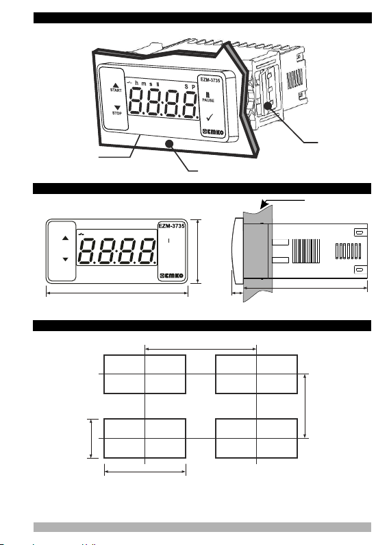
During putting equipment in hole on the metal panel while mechanical installation some metal
burrs can cause injury on hands, you must be careful.
Montage of the product on a system must be done with it’s fixing clamps. Do not do the montage
of the device with inappropriate fixing clamp. Be sure that device will not fall while doing the
montage.
It is your responsibility if this equipment is used in a manner not specified in this instruction
manual.
EMKO Elektronik warrants that the equipment delivered is free from defects in material and
workmanship. This warranty is provided for a period of two years. The warranty period starts
from the delivery date. This warranty is in force if duty and responsibilities which are determined
in warranty document and instruction manual performs by the customer completely.
Repairs should only be performed by trained and specialized personnel. Cut power to the
device before accessing internal parts.
Do not clean the case with hydrocarbon-based solvents (Petrol, Trichlorethylene etc.). Use of
these solvents can reduce the mechanical reliability of the device. Use a cloth dampened in
ethyl alcohol or water to clean the external plastic case.
1.3 Installation
1.4 Warranty
1.5 Maintenance
1.6 Manufacturer Company
Manufacturer Information:
Emko Elektronik Sanayi ve Ticaret A.Ş.
Demirtaş Organize Sanayi Bölgesi Karanfil Sk. No:6 16369 BURSA/TURKEY
Phone : +90 224 261 1900
Fax : +90 224 261 1912
Repair and maintenance service information:
Emko Elektronik Sanayi ve Ticaret A.Ş.
Demirtaş Organize Sanayi Bölgesi Karanfil Sk. No:6 16369 BURSA /TURKEY
Phone : +90 224 261 1900
Fax : +90 224 261 1912

2.2 Panel Cut-Out
2. General Description
2.1 Front View and Dimensions of EZM-3735 Digital Timer
Mounting Clamp
Panel Surface
(maximum thickness 15 mm / 0.59 inch)
Front Panel
IP65 protection
NEMA 4X
4
76 mm / 3 inch 6 mm / 0.24 inch
34,5 mm / 1.36 inch
65 mm / 2.56 inch
Maximum 15 mm / 0.59 inch
110 mm / 4.33 inch (min)
71 mm / 2.79 inch
29 mm / 1.14 inch
50 mm / 1.97 inch (min)
P
S
hs
m
START
STOP ü
PAUSE

4. Electrical Wiring Diagram
5
1-Before mounting the device in your panel,
make sure that the cut-out is of the right size.
2-Insert the device through the cut-out. If the
mounting clamps are on the unit, put out them
before inserting the unit to the panel.
3- Insert the mounting clamps to the fixing sockets
that located left and right sides of device and make
the unit completely immobile within the panel
1-Pull mounting clamps from left and right fixing
sockets.
2-Pull the unit through the front side of the panel
Before starting to remove the unit from
panel, power off the unit and the related
system.
c
2.3 Panel Mounting
2.4 Removing from the Panel
Relay Output
21 4 5 7 8
P/N : EZM-3735
L
N
a
Pause
Digital Input
230V ( %15) 50/60Hz
115V ( %15) 50/60Hz
24V ( %15) 50/60Hz
Z
V ±
V ±
V ±
10..30 V
Must be determined in order.
3 6
Supply Voltage Input
3
1
3
2
3
2
1

4.2 Device Label and Connection Diagram
4.1 Supply Voltage Input Connection of the Device
Note-1 : External fuse is recommended.
Make sure that the power supply voltage is the same
indicated on the instrument.
Switch on the power supply only after that all the electrical
connections have been completed.
Supply voltage range must be determined in order. While
installing the unit, supply voltage range must be controlled
and appropriate supply voltage must be applied to the unit.
c
There is no power supply switch on the device. So a power
supply switch must be added to the supply voltage input.
Power switch must be two poled for seperating phase and
neutral, On/Off condition of power supply switch is very
important in electrical connection.
External fuse that on Vpower supply inputs must be on
phase connection.
External fuse that on Zpower supply inputs must be on (+)
connection.
c
230VV CONNECTION DIAGRAM
6
Power Supply Connection
c
a
EXTERNAL
FUSE
(1A T)
Note-1
Supply
Switch
Supply Voltage
45
LN
230V ( %15) 50/60Hz ,
115V ( %15) 50/60Hz,
24V ( %15) 50/60Hz ,
Z
V ±
V±
V ±
10...30 V 1.5 W
Must be determined in order.
78
a
16A
@250VV1HP
LN
245
1
START
L
N
16A T Fuse
3
OUTPUT
NO NCC
LOAD
6
PAUSE
16A @
250VV1HP
230 VV ± 15%
50/60Hz - 1.5VA
LINE
OUTPUT
NO NCC
LOAD
7
8
PAUSE
START

5.Front Panel Definition and Accessing to the Menus
BUTTON DEFINITIONS
1. Increment Button and Start Button :
** It is used to increase the value in the Set screen and Programming mode.
** It is used for Start the Timer in the Main Screen.
2. Decrement, Silencing Buzzer and Stop Button :
** It is used to decrease the value in the Set screen and Programming mode.
** It is used to silence the buzzer.
** It is used for Stop the Timer in the Main Screen.
3. Pause Button :
** While digital timer is running if Pause button is pressed or external pause input is activated,
timer stops running.After that if the pause button is pressed again or external pause input is
deactivated, timer starts running again.
4. Enter Button:
** In the main operation screen; if this button pressed, set value will be displayed. Value can be
changed using increment and decrement buttons. When Set button pressed again, value is
saved and returns back to main operating screen.
** To access the programming screen; in the main operation screen, press this button for 5
seconds.
** It is used to saving value in the Set screen and programming screen.
LED DEFINITIONS
5. Output led :
** This led indicates that Output is active.
6.Hour led :
** Indicates that device is in Hour mode.
7.Minute led :
** Indicates that device is in Minute mode.
8.Second led :
** Indicates that device is in Second mode.
9.Pause led :
** This led indicates that Pause is active.
10.Set led :
** Indicates that device is in Set value changing mode.
11.Program led :
**Blinks in programming mode .
7
6 7
3
4
1
2
3
5
6
7
8
7
10
11
9

6. Changing and Saving Timing Set Value
Main Operation Screen
When Enter button pressed ‘’S’’ led will
be active and temperature set value will
be displayed.
SET Value Screen
Timer set value can be
changed with increment and
decrement buttons.
When Enter button pressed Timing set
value can be saved.
‘’S’’ will be inactive and goes back to
main operation screen.
Main Operation Screen
Timer set value parameter (Default=01:00)
Timer set value, can be programmed between minimum Timer set value 00:01 and maximum
set limit.
8
6.1 Programming Mode Parameter List
Start Type Selection Parameter ( Default = )
Output Functions (Default = )
Time Unit and Scale Selection ( Default = 1 ) Parameter
Hour / Minute
It can be adjusted from to .
Minute /Second
It can be adjusted from to .
Filter Time of Digital Inputs ( Default = 100 )
It is used for protection against the electrical contact debounce or the signal that is less than
the determined pulse time.
It can be adjusted from to msec .
Second /10 Milisecond
It can be adjusted from to .
Start / Stop buttons can be used to run or stop the timer.
External Start Input can only be used to run the timer. In order to stop the timer
the Stop button must be used.
External Start Input can be used to run or stop the timer.
if ON is selected timer runs by start and relay contact is closed. When time is
over, relay contact opens.
if OFF is selected timer runs by start. When time is over, relay contact is closed.
Start / Stop buttons can be used to run or stop the timer.
For detailed information refer to graphics.

9
Output Relay On Delay Time ( Default = 0 )
It determines how long output relay will be active. If it is 0000 second, then it operates
indefinitely.
= .
It can be adjusted from to minute/second. This parameter is
active only if
Buzzer Function Selection Parameter ( Default = 0 )
if this parameter is selected 0, Buzzer is inactive. Adjustable 16 different buzzer sounds.
It can be adjusted from 0 to16.
Buzzer is active during this time ( Default = )
Buzzer stays active during this time. It can be adjusted from 1 to 99 seconds When this
parameter is 1, if decrement button is pressed, is observed. In this condition
buzzer is active till buzzer Stop button is pressed.
Programming Section Access Password
.
( Default = 0 )
It is used for accessing to the programming section. It can be adjusted from 0 to 9999. If it is
selected 0, password will not be asked
Data Record ( Default = 1 )
Timer count value is saved to memory when power is disconnected and restored
on power up.
Timer count value is not saved to memory when power is disconnected. When
power up, Set value is shown on the screen.
Maximum Set Value Parameter ( Default = 01:00)
Maximum set value for set time value.
It can be adjusted from to .
( If time value is monitored in miliseconds. )
( If time value is monitored in Hours or
Minutes. )
Timer Counting Direction ( Default = 1 )
Timer upcount. 0 to Set value.
Timer Downcount. Set value to 0.
Button Protection Parameter 0( Default = )
Button protection is not active.
Buttom protection is active for Timer set value.

10
6.3 Operation Graphics of ESM-3735 Digital Timer
1.1 If Start type is selected as .
1.1.1 If downcount =1 and is the control diagram is shown in Figure 1.1
1.Control diagram using Start / Stop buttons.
1.1.2 If downcount =1 and is the control diagram is shown in Figure 1.2
Figure 1.1 Figure 1.2
1.2 If Start type is selected as .
1.2.1 If Upcount =0 and is the control diagram is shown in Figure 1.3
1.2.2 If Upcount =0 and is the control diagram is shown in Figure 1.4
Figure 1.3 Figure 1.4
Power
Output
Start
Button
Stop
Button
Set
Screen
Power
Output
Start
Button
Stop
Button
Set
Screen
Pause PausePause Pause
Power
Output
Start
Button
Stop
Button
Set
Screen
Power
Output
Start
Button
Stop
Button
Set
Screen
Pause Pause

11
2.1 If Start type is selected as .
2.1.1 If Downcount =1 and is the control diagram is shown in Figure 2.1
2.2.2 If Downcount =1 and is the control diagram is shown in Figure 2.2
Figure 2.1 Figure 2.2
1.4 If Start type is selected as .
1.4.1 If Upcount =0 and is the control diagram is shown in Figure 2.3
1.4.2 If Upcount =0 and is the control diagram is shown in Figure 2.4
Figure 2.3 Figure 2.4
2.Control diagram using Start / Stop buttons.
Power
Output
Start
Button
Stop
Button
Set
Screen
Power
Output
Start
Button
Stop
Button
Set
Screen
Pause Pause
Power
Output
Start
Button
Stop
Button
Set
Screen
Power
Output
Start
Button
Stop
Button
Set
Screen
Pause Pause

12
3.1 If Start type is selected as .
3.1.1 If Downcount =1 and is the control diagram is shown in Figure 3.1
3.1.2 If Downcount =1 and is the control diagram is shown in Figure 3.2
Figure 3.1 Figure 3.2
3.2.1 If Upcount =0 and is the control diagram is shown in Figure 3.3
3.2.2 If Upcount =0 and is the control diagram is shown in Figure 3.4
Figure 3.3 Figure 3.4
3.Control diagram using External Digital Start Input.
Power
Output
Start
Input
Set
Screen
Power
Output
Start
Input
Set
Screen
Pause Pause
Power
Output
Start
Input
Set
Screen
Power
Output
Start
Input
Set
Screen
Pause Pause

13
4.1 If Start type is selected as .
4.1.1 If Downcount =1 and is the control diagram is shown in Figure 4.1
4.1.2 If Downcount =1 and is the control diagram is shown in Figure 4.2
Figure 4.1 Figure 4.2
4.2.1 If Upcount =0 and is the control diagram is shown in Figure 4.3
4.2.2 If Upcount =0 and is the control diagram is shown in Figure 4.4
Figure 4.3 Figure 4.4
4.Control diagram using External Digital Start Input.
Power
Output
Start
Input
Stop
Button
Set
Screen
Power
Output
Start
Input
Stop
Button
Set
Screen
Pause Pause
Power
Output
Start
Input
Stop
Button
Set
Screen
Power
Output
Start
Input
Stop
Button
Set
Screen
Pause Pause

14
When Enter button is pressed for 5
seconds, “P” led starts to blink. If
programming mode entering
password is different from 0,
programming mode entering screen
will be observed.
Main Operation Screen
Programming Screen
Change the value with increment
and decrement buttons.
Filter Time of Start Input
Press Enter button for accessing to the parameter
value. Press increment button for accessing to the
next parameter, press decrement button for
accessing to the previous parameter.
Press OK button for saving
the parameter. Press increment button for accessing to the
next parameter, press decrement button for
accessing to the previous parameter
Password Entering Screen
Programming Mode
Entering Screen
Press Enter button for
accessing to the
password entering
screen.
Password Entering Screen
Enter programming mode accessing password
with increment and decrement buttons.
Note2: If programming mode accessing password is 0, only three parameters
are accessible, and the parameter values can be changed.
Press OK button for entering
the password.
Note1: If programming
mode accessing
password is 0,
Temperature Unit screen
is observed instead of
programming screen
Filter Time of Start Input
If no operation is performed in programming mode for 20 seconds, device turns to main
operation screen automatically..
i
Filter Time of Start Input
6.5 Entering To The Programming Mode, Changing and Saving Parameter
ü
PAUSE
ü
PAUSE
ü
PAUSE
ü
PAUSE
ü
PAUSE
ü
PAUSE
ü
PAUSE
ü
PAUSE

15
Device Type : Digital Timer
Housing&Mounting : 76mm x 34.5mm x 71mm plastic housing for panel
Mounting. Panel cut-out is 71x29mm.
Protection Class : Ip65 at front, Ip20 at rear.
Weight : Approximately 0.20 Kg.
Environmental Ratings : Standard, indoor at an altitude of less than 2000 meters
with none condensing humidity.
o o o o
Storage / Operating Temperature : -40 C to +80 C / -30 C to +80 C
Storage / Operating Humidity : 90 % max. (None condensing)
Installation : Fixed installation
Overvoltage Category : II.
Pollution Degree : II, office or workplace, none conductive pollution
Operating Conditions : Continuous
Supply Voltage and Power :
: 115
: 24
Time Accuracy : within
Digital Start and Pause Inputs : Mechanical contact
Control Form : ON / OFF
Relay Output : 16(8) A@250 V V for Resistive load (Output Relay)
(Electrical life : 100.000 switching at full load)
Display : 14 mm Red 4 digits LED Display
LED : S (Green), P (Green), h (Red), m(Red),s (Red),
Output (Red)
Internal Buzzer : ³83dB
Approvals : ,
230V ( %15) 50/60Hz - 1.5VA
V ( %15) 50/60Hz - 1.5VA
V ±
V ±
V ±
±%1 error
7. Specifications

16
All order information of EZM-3735 Digital Timer are given on the table at above. User may form
appropriate device configuration from information and codes that at the table and convert it to the
ordering codes. Firstly, supply voltage then other specifications must be determined. Please fill the order
code blanks according to your needs.
Please contact us, if your needs are out of the standards.
8.Ordering Information
A BC D E FG HI /
/
UV W Z/
/
0 0 0
1Relay Output (16(8) A@250 V V,at resistive Load, 1 NO+NC )
Output
E
Supply VoltageA
EZM-3735
4115V ( %15) 50/60Hz - 1.5VAV ±
5230V ( %15) 50/60Hz - 1.5VAV ±
07 07
810 - 30 V Z
(77x35 DIN Sizes)
Your Technology Partner
www.emkoelektronik.com.tr
Thank you very much for your preference to
use Emko Elektronik products, please visit our
web page to download detailed user manual.
0 1 01
07 Digital Input
Input
FG
07 Digital Input
Input
HI
324V ( %15) 50/60Hz - 1.5VAV ±

EZM-3735 77x35 DIN-Größe Digitaltimer-Steuerung
Bedienungsanleitung. DE EZM-3735 01 V02 09/14
- 4-stellige Anzeige
- Betrieb mit einem Sollwert
- Einzelkontaktausgang für Zeitsteuerung (EIN/AUS)
- Externe Start- und Pauseneingabe
- Start- und Stoppmöglichkeit über Bedienfeld
- Pausenfunktion über Bedienfeld
- Obere Sollwertbegrenzung
- Anzeige kann eingestellt werden, damit Sekunden,
Minuten und Stunden angezeigt werden
- Programmierbare Zeitbasen (Sekunde, Minute, Stunde)
- Einstellbarer interner Summer gemäß Timer-Stopp-Status.
- Passwortschutz für Programmierbereich
- CE-Kennzeichnung gemäß Europäischen Normen
EZM-3735 77 x 35 DIN-Größe
Digitaltimer-Steuerung
DEUTSCH

Betriebstemperatur : 0 bis 50 °C
Max. Luftfeuchtigkeit bei Betrieb : 90% Rh (nicht kondensierend)
Höhe : Bis zu 2000 m.
Verbotene Bedingungen:
Korrosive Atmosphäre
Explosionsfähige Atmosphäre
Heimbereich (Das Gerät ist nur für industrielle Anwendungen)
c
1.2 Allgemeine Spezifikationen
1. Einleitung
Der EZM-3735 Programmierbare Timer kann für Verpackungsmaschinen, Produktions- und
Qualitätskontrollrollen verwendet werden und ist leicht an alle mechanischen Konstruktions-
und Automatisierungssysteme anzupassen.
Anwendungsbereiche
Verpackungsmaschinen,
Qualitätskontrollrollen,
Abfüllanlagen,
Werkbänke,
Gebäudeautomation,
Produktionsbänder.
EZM-3735
2
Ausgangsrelais
EIN/AUS Betrieb
1.1 Umgebungsbedingte Leistungsfähigkeit
Ausgang
Stromversorgungs-
eingang
Digitaler Eingang
Starteingabe
230V ( %15) 50/60HzV ±
Optionale Versorgungsspannung
- 30 V Z
115 V (±%15) 50/60Hz,
24 V (±%15) 50/60Hz,
10
V
V
Standard
Pauseneingabe Digitaler Eingang

3
Eine Sichtprüfung dieses Produkts auf mögliche Transportschäden wird vor der Installation
empfohlen. Es liegt in Ihrer Verantwortung dafür zu sorgen, dass qualifizierte Maschinenbau-
und Elektrotechniker dieses Produkt installieren.
Bei Gefahr eines schweren Unfalls durch Ausfall oder Defekt dieser Einheit, schalten Sie das
System aus und trennen Sie die elektrische Verbindung des Geräts vom System.
Die Einheit wird normalerweise ohne Stromschalter oder Sicherung geliefert. Verwenden Sie
Netzschalter und Sicherung nach Bedarf.
Stellen Sie sicher, dass Sie die Nennversorgungsspannung verwenden, um die Einheit vor
Schäden zu schützen und einen Ausfall zu verhindern.
Lassen Sie den Strom abgeschaltet, bis die gesamte Verkabelung abgeschlossen ist, damit
Stromschläge und Probleme mit dem Gerät verhindert werden können.
Versuchen Sie niemals die Einheit zu zerlegen, zu verändern oder zu reparieren.
Die Manipulierung des Geräts kann zu Fehlfunktion, Stromschlag oder Brand führen.
Verwenden Sie die Einheit nicht in brennbaren oder explosionsgefährdeten gashaltigen
Atmosphären.
Beim Einsetzen des Geräts in die Öffnung der Metallplatte während der mechanischen
Installation, können Metallgrate Verletzungen an den Händen verursachen. Seien Sie
vorsichtig.
Die Montage des Produkts in einem System muss mit dessen Befestigungsklammern erfolgen.
Führen Sie die Montage des Geräts nicht mit ungeeigneten Befestigungsklammern durch.
Achten Sie darauf, dass das Gerät während der Montage nicht herunterfällt.
Es liegt in Ihrer Verantwortung, wenn das Gerät auf eine nicht in dieser Bedienungsanleitung
vorgeschriebenen Art und Weise benutzt wird.
EMKO Elektronik garantiert, dass das gelieferte Gerät keinerlei Material- oder Verarbeitungsmängel
aufweist. Diese Garantie beschränkt sich auf einen Zeitraum von zwei Jahren. Die Garantiezeitbeginnt
mit dem Lieferdatum. Diese Garantie ist gültig, wenn die im Garantieschein und in der
Bedienungsanleitung festgelegten Pflichten und Verantwortlichkeiten vollständig durch den Kunden
erfüllt werden.
Reparaturen dürfen nur von geschultem Fachpersonal durchgeführt werden. Trennen Sie das Gerät
von der Stromversorgung, bevor Sie Innenteile manipulieren. Reinigen Sie das Gehäuse nicht mit
Kohlenwasserstoff-Lösemitteln (Benzin, Trichloräthylen usw.). Die Verwendung dieser
Lösemittelkann die mechanische Zuverlässigkeit des Geräts beeinträchtigen. Verwenden Sie ein mit
Ethylalkohol oder Wasser angefeuchtetes Tuch, um das externe Kunststoffgehäuse zu reinigen.
1.3 Installation
1.4 Garantie
1.5 Wartung
1.6 Herstellerfirma
Herstellerangaben:
Emko Elektronik Sanayi ve Ticaret A.Ş.
Demirtaş Organize Sanayi Bölgesi Karanfil Sk. No:6 16369 BURSA/TURKEY
Telefon : +90 224 261 1900
Fax : +90 224 261 1912
Reparatur und Wartungsservice:
Emko Elektronik Sanayi ve Ticaret A.Ş.
Demirtaş Organize Sanayi Bölgesi Karanfil Sk. No:6 16369 BURSA /TURKEY
Telefon : +90 224 261 1900
Fax : +90 224 261 1912

2.2 Tafelausschnitt
2. Allgemeine Beschreibung
2.1 Frontansicht und Abmessungen des EZM-3735 Digitaltimers
Befestigungsklammer
Tafeloberfläche
(maximale Dicke 15 mm / 0,59 Zoll)
Bedienfeld
IP 65 Schutz
NEMA 4X
4
76 mm / 3 Zoll 6 mm / 0,24 Zoll
34,5 mm / 1.36 inch
65 mm / 2,56 Zoll
Maximum 15 mm / 0,59 Zoll
110 mm / 4,33 Zoll (min)
71 mm / 2,79 Zoll
29 mm / 1,14 Zoll
50 mm / 1,97 Zoll (min)
P
S
hs
m
START
STOP ü
PAUSE
This manual suits for next models
1
Table of contents
Languages:
Other EMKO Timer manuals